EP0960265B1 - Rückhaltesystem für schneidwerkzeughalter - Google Patents
Rückhaltesystem für schneidwerkzeughalter Download PDFInfo
- Publication number
- EP0960265B1 EP0960265B1 EP98904679A EP98904679A EP0960265B1 EP 0960265 B1 EP0960265 B1 EP 0960265B1 EP 98904679 A EP98904679 A EP 98904679A EP 98904679 A EP98904679 A EP 98904679A EP 0960265 B1 EP0960265 B1 EP 0960265B1
- Authority
- EP
- European Patent Office
- Prior art keywords
- pin
- toolholder
- bore
- block
- jam
- Prior art date
- Legal status (The legal status is an assumption and is not a legal conclusion. Google has not performed a legal analysis and makes no representation as to the accuracy of the status listed.)
- Expired - Lifetime
Links
- 230000014759 maintenance of location Effects 0.000 title claims abstract description 32
- 238000009412 basement excavation Methods 0.000 claims abstract description 24
- 230000013011 mating Effects 0.000 claims description 22
- 230000008901 benefit Effects 0.000 description 6
- 239000000463 material Substances 0.000 description 5
- 238000003466 welding Methods 0.000 description 4
- 238000000034 method Methods 0.000 description 3
- 238000005065 mining Methods 0.000 description 3
- 230000004048 modification Effects 0.000 description 3
- 238000012986 modification Methods 0.000 description 3
- 229910000831 Steel Inorganic materials 0.000 description 2
- 239000010959 steel Substances 0.000 description 2
- 229910001104 4140 steel Inorganic materials 0.000 description 1
- 230000009471 action Effects 0.000 description 1
- 239000000853 adhesive Substances 0.000 description 1
- 230000001070 adhesive effect Effects 0.000 description 1
- 230000003466 anti-cipated effect Effects 0.000 description 1
- 230000000712 assembly Effects 0.000 description 1
- 238000000429 assembly Methods 0.000 description 1
- 230000008859 change Effects 0.000 description 1
- 238000010276 construction Methods 0.000 description 1
- 229920006332 epoxy adhesive Polymers 0.000 description 1
- 238000003801 milling Methods 0.000 description 1
- 230000002028 premature Effects 0.000 description 1
- 230000008439 repair process Effects 0.000 description 1
- 239000011343 solid material Substances 0.000 description 1
- UONOETXJSWQNOL-UHFFFAOYSA-N tungsten carbide Chemical compound [W+]#[C-] UONOETXJSWQNOL-UHFFFAOYSA-N 0.000 description 1
Images
Classifications
-
- E—FIXED CONSTRUCTIONS
- E21—EARTH OR ROCK DRILLING; MINING
- E21C—MINING OR QUARRYING
- E21C35/00—Details of, or accessories for, machines for slitting or completely freeing the mineral from the seam, not provided for in groups E21C25/00 - E21C33/00, E21C37/00 or E21C39/00
- E21C35/18—Mining picks; Holders therefor
- E21C35/19—Means for fixing picks or holders
- E21C35/193—Means for fixing picks or holders using bolts as main fixing elements
-
- E—FIXED CONSTRUCTIONS
- E21—EARTH OR ROCK DRILLING; MINING
- E21C—MINING OR QUARRYING
- E21C35/00—Details of, or accessories for, machines for slitting or completely freeing the mineral from the seam, not provided for in groups E21C25/00 - E21C33/00, E21C37/00 or E21C39/00
- E21C35/18—Mining picks; Holders therefor
- E21C35/19—Means for fixing picks or holders
- E21C35/191—Means for fixing picks or holders for fixing holders
Definitions
- This invention relates to excavation cutting tools, and more particularly to a retention system for retaining an excavation cutting toolholder in a support block during use.
- Excavation cutting tool assemblies for such applications as continuous mining or road milling typically comprise a cutting tool, sometimes referred to as a cutting bit, rotatably mounted within a support block.
- the support block in turn is mounted onto a drum or other body, typically by welding, which in turn is driven by a suitable power means.
- a suitable power means When a number of such support blocks carrying cutting tools are mounted onto a drum, and the drum is driven, the cutting tools will engage and break up the material which is sought to be mined or removed.
- the general operation of such a mining or construction machine is well known in the art.
- a cutting toolholder sometimes referred to as a cutting tool sleeve, bit holder, or bit sleeve
- the cutting tool is rotatably or otherwise releasably mounted within the bit holder which in turn is mounted within the support block via some mechanical connection. This helps to protect the support block from abuse and wear, thus minimizing or eliminating the down time periods otherwise required for drum repair.
- the use of such bit holders is well known in the art. For example, U.S. Patent No. 5,067,775 to D'Angelo discloses the use of such a bit holder which is referred to as a sleeve in that patent.
- U.S. Patent No. 3,749,449 to Krekeler discloses a support block having two upstanding members or bifurcations which define therebetween a channel into which fits a toolholder.
- a pin passes through the support block and the cutting toolholder and releasably secures the toolholder to the support block.
- the Krekeler patent relies on cooperation between the bottom surface of the cutting toolholder and an upper surface of the support block, at the bottom of the channel, to resist forces tending to pivot the cutting toolholder about the pin.
- the Krekeler patent relies upon a close tolerance fit to minimize rotational movement of the cutting tool and cutting toolholder about the pin during use. Otherwise, movement of the cutting toolholder in the support block will cause unnecessary wear to the cutting tool, the cutting toolholder, and the support block.
- U.S. Patent No. 4,650,254 to Wechner discloses the use of two bolts to connect a cutting toolholder to a block.
- the two bolts pass horizontally through the rear surface of the support block and through the shank portion of the cutting toolholder. Such a connection may be subject to vibratory loosening.
- An object of the present invention is to provide an improved excavation cutting toolholder retention system which allows a cutting toolholder to be securely fastened to a support block in such a manner as to minimize or eliminate any movement or loosening of the cutting holder within the support block.
- an excavation cutting toolholder retention system is provided according to the features of claim 1.
- the support block has block pin bores which define the block engagement surface and are inclined downwardly.
- the holder engagement surface of the cutting toolholder is a transverse pin bore.
- the pin runs through and engages the transverse pin bore of the cutting toolholder.
- the pin has a pin shaft, a first jam member, and a second jam member, the first and second jam members each having a block engagement portion which moveably engages the block pin bores.
- the pin shaft also has a pin flange which engages the flange recess so as to limit translational movement of the pin shaft within the transverse pin bore. At least one of the first and second jam members is moveable along the pin shaft relative to the other of the first and second jam members such that the block engagement portion of the first and second jam members is moved along the block pin bores and the cutting toolholder is drawn into the toolholder bore.
- the pin shaft has a threaded portion and one of the first and second jam members has a threaded jam bore such that one of the first and second jam members may threadably engage the pin shaft and be moved relative to the other of the first and second jam members.
- the first jam member may have a first aligned cylindrical portion and a first angled cylindrical portion and the second jam member may have a second aligned cylindrical portion and a second angled cylindrical portion such that the first and second aligned cylindrical portions engage the transverse pin bore of the cutting toolholder and the first and second angled cylindrical portions define the block engagement portion and engage the block pin bores.
- the cutting toolholder has a holder slot intersecting the transverse pin bore such that the cutting toolholder may be removed from the toolholder bore of the support block by moving the second jam member relative to the first jam member such that the first and second jam members do not interfere with the transverse pin bore and the cutting tcolholder may be withdrawn from the toolholder bore while the first and second jam members still moveably engage the block pin bores.
- the toolholder has a holder shoulder and the support block has a seating shoulder region adjacent the toolholder bore.
- the holder shoulder will abut the seating shoulder region.
- the pin shaft has a pin shaft axis and a pin shaft diameter and the pin flange is a cylindrical portion about the pin shaft axis, the cylindrical portion having a cylindrical portion diameter greater than the pin shaft diameter.
- the flange recess is a pin flange slot which intersects the transverse pin bore.
- the present invention also includes a pin for use with a support block and a cutting toolholder according to the features of claim 19.
- the first and second angled cylindrical portions have a mating groove.
- the pin shaft has a pin shaft axis and a pin shaft diameter and the pin flange is a cylindrical portion about the pin shaft axis, the cylindrical portion having a cylindrical portion diameter greater than the pin shaft diameter.
- the cutting toolholder will be drawn into an especially tight relationship with the toolholder bore.
- This tight fit is especially secure if one or both of the shank portion or toolholder bore is tapered so that the shank portion of the cutting tool is wedged into the toolholder bore when the components are engaged by utilizing the pin.
- the security of the fit is also increased if the toolholder has a holder shoulder which abuts a seating shoulder region of the support block when the cutting toolholder is drawn into the toolholder bore.
- the toolholder bore of the support block may have a configuration so as to completely surround and provide multi-directional support to the cutting toolholder.
- the pin flange resides within the flange recess of the cutting toolholder during use, translational movement of the pin shaft is limited. As a result, binding of the first and second jam members will be reduced or prevented and the jam members will be kept at approximately the same distance from the center of the pin during loosening so to help ensure easy removal of the cutting toolholder.
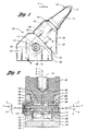
- FIG. 1 is a side view of a support block, cutting toolholder, and cutting tool showing one embodiment of the invention
- FIG. 2 is a sectional view taken along the plane indicated by line 2--2 in FIG. 1, the left half showing the invention in the loose condition and the right half showing the tightened condition;
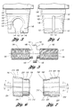
- FIG. 3 is a side view of the shank portion of the cutting toolholder showing the holder slot
- FIG. 4 is a side view of the shank portion of the cutting toolholder showing the pin slot
- FIG. 5 is a side view of a threaded pin
- FIG. 6 is a side view of a first jam member
- FIG. 7 is a side view of a second jam member.
- the cutting toolholder retention system 100 includes a support block 102 having a toolholder bore 104 and block pin bores 106 and a cutting toolholder 108 having a holder shank portion 110 mated to the support block 102 via a pin 112.
- a cutting tool 114 may be rotatably and releasably mounted within the cutting toolholder 108.
- the scope of this invention would cover cutting toolholder retention systems in which the cutting tool is non-rotatably mounted.
- such support blocks 102 can be distributed over and fastened to, such as by welding, the circumference and length of a drum or other body (not shown) according to any desired pattern.
- the drum or other body may be driven by any conventional and suitable power means to cause the cutting tools 114 to engage and break up material that they are applied to.
- Such applications are well known in the art, and will not be described further here.
- the cutting tool 114 typically has an elongated body.
- the cutting end 120 of the cutting tool 114 typically comprises a hard cutting insert 122 mounted onto a generally conical outer region 124.
- This hard cutting insert 122 may be made from cemented tungsten carbide or any other suitable material.
- the hard cutting insert 122 is generally mounted at the end of the conical outer region 124 where the cutting insert 122 may be brazed or otherwise suitably fastened into place.
- the cutting tool 114 also includes a tool shank 126 adjoining a shoulder 128 of the conical outer region 124. Because such cutting tools are generally known in the art, they need not be described in further detail here.
- Cutting toolholders may have a variety of configurations.
- the cutting toolholder 108 shown in this embodiment has an outer wear region 130 and the shank portion 110 joined at a holder shoulder 132.
- the cutting toolholder 108 defines a tool bore 134 in which the cutting tool 114 may be rotatably or otherwise mounted.
- Such rotatable or non-rotatable mountings are well known in the art, and will not be described in further detail here.
- the shank portion 110 of the cutting toolholder 108 may have a variety of configurations, the shank portion 110 as shown in this embodiment is tapered along a center axis "A".
- the shank portion 110 may be made of solid material, or as shown here, may have a cavity such as a vertical bore 136.
- the shank portion 110 also has a holder engagement recess which in this embodiment comprises a transverse pin bore 138.
- the transverse pin bore 138 in this embodiment is cylindrical and aligned along a center axis designated "B" and which preferably intersects the center axis "A" of the shank portion 110.
- the holder engagement recess has a holder engagement surface 140 which in the embodiment shown is the surface defined by the transverse pin bore 138, especially the lower surface when locking the toolholder 108 and the upper surface when releasing the toolholder 108.
- the holder shank portion 110 defines a holder slot 142 defined by two vertical slot sides 144 which intersect the transverse pin bore 138. As best shown in Figures 2 and 3, on each end of the transverse pin bore 138 the holder shank 110 also defines jam recesses 146 having vertical recess walls 148. As best shown in Figure 4, the holder shank 110 additionally defines a pin flange recess which in this embodiment is a pin flange slot 150.
- the pin flange slot 150 in this embodiment is defined by two vertical slot sides 152 and perpendicularly intersects the transverse pin bore 138. In this embodiment, the two vertical slot sides 152 have chamfers 153 at the lower end of the holder shank portion 110.
- the support block 102 typically has the toolholder bore 104 surrounded by a seating shoulder region 160.
- the toolholder bore 104 in this preferred embodiment is tapered so as to match the taper of the shank portion 110 of the cutting toolholder 108. It has been found preferable that the maximum total included taper angle be approximately 16°.
- the support block 102 also has a side surface 162 and a base 164 which may be mounted to a drum or other body (not shown) by way of welding or any other suitable method.
- the toolholder bore 104 and accordingly the cutting toolholder 108 and the cutting tool 114, is typically pitched in the direction of travel of the cutting tool 114, designated as direction "C" in Figure 1.
- the toolholder bore 104 of the support block 102 may be partially surrounded but is more typically fully surrounded by a seating shoulder region 160.
- the toolholder bore 104 of this embodiment has a holder bore center axis "A'" which coincides with the axis "A" of the shank portion 110 of the cutting toolholder 108 when the components are assembled as shown.
- the support block 102 has the block pin bores 106, which are cylindrical and aligned along block pin bore axes designated "D.” As shown in Figure 2, the block pin bore axes "D” intersect the axis "B” of the transverse pin bore 138 at an angle "E.”
- the block pin bores 106 have a block engagement surface 164, which in the embodiment shown is the surface defined by the block pin bores 106, especially the upper surface when locking the toolholder 108 and the lower surface when releasing the toolholder 108. As shown in FIG. 2, the block engagement surface 164, and in this embodiment the block pin bores 106 having axes "D,” are inclined downwardly relative to the toolholder bore 104.
- the block pin bores 106 also define pin bore grooves 166 along the lower surface of the pin bores 106.
- the pin bore grooves 166 in this embodiment are semi-cylindrical in shape.
- Mating pins 170 having a cylindrical configuration reside within the pin bore grooves 166.
- the mating pins 170 may be press fit into the pin bore grooves 166 in which case the pin bore grooves 166 will have a cross section configuration slightly greater than a half circle or may be held in position using any suitable fastening method such as by tack welding or epoxy adhesives.
- the mating pins 170 may be made of any suitable material, such as 52100 steel.
- the pin 112 includes a pin shaft 180 having a pin shaft diameter, a first jam member 182 and a second jam member 184 which are assembled along the center axis "B."
- the pin shaft 180 in this embodiment has a first pitch threaded portion 186, an unthreaded portion 188 including a pin flange 190 having pin flange sides 191, and a second pitch threaded portion 192. While the pin flange 190 is required in this embodiment, the pin shaft need not have an unthreaded portion.
- the pin flange 190 may have any suitable configuration as long as it has a greater diameter than the pin shaft 180 and will fit within the pin flange slot 150 of the holder shank 110.
- the pin flange 190 is a cylindrical portion 193 about the pin shaft axis "B" and the cylindrical portion 193 has a cylindrical portion diameter greater than the pin shaft diameter. Furthermore, in the embodiment shown, the dimension between the pin flange sides 191 should be less than the dimension between the vertical slot sides 152 such that the pin shaft 180 may be rotated within the retention system 100 as will be explained.
- the pin shaft 180 also has an engagement structure 194 which, in the embodiment shown, constitutes hexagonal recesses centered along the axis "B" of the pin shaft 180.
- the first jam member 182 has an aligned cylindrical portion 196 aligned along the axis "B," the outer end of which has a chamfer 198, preferably at an angle of 45° to the axis "B.”
- Adjoining the aligned cylindrical portion 196 at a jam shoulder 200 is an angled cylindrical portion 202 having a center axis "D" set at an angle "E" to the axis "B.”
- the first jam member 182 also defines a threaded jam bore 204 which, in the embodiment shown, constitutes a left hand threaded bore manufactured to threadably engage the first pitch threaded portion 186 of the pin shaft 180.
- the first jam member 182 also defines a mating groove 206 along the lower surface of the angled cylindrical portion 202.
- the mating groove 206 has a semi-cylindrical configuration designed to mate with the mating pin 170 as will be explained in further detail.
- the pin 112 has a pin engagement surface 210.
- the pin engagement surface 210 has a holder engagement portion 212 and a block engagement portion 214.
- the holder engagement portion 212 is the outer surface, especially the lower surface when locking and upper surface when releasing, of the aligned cylindrical portion 196.
- the block engagement portion 214 is the outer surface, especially the upper surface when locking and the lower surface when releasing, of the angled cylindrical portion 202.
- the second jam member 184 is a mirror image duplicate of the first jam member 182.
- the second jam member 184 has an aligned cylindrical portion 196', a chamfer 198', and a jam shoulder 200', an angled cylindrical portion 202', a threaded jam bore 204' which in the embodiment shown has a right hand thread manufactured to threadably engage the second pitch threaded portion 192 of the pin shaft 180.
- the second jam member 184 also has a pin engagement surface 210' including a holder engagement portion 212' and a block engagement portion 214'.
- the angled cylindrical portion 202' of the second jam member 184 has an axis "D" set at an angle "E" to the center axis "B" of the aligned cylindrical portion 196'.
- first jam member 182 is shown as having a left hand threaded jam bore 204 and the second jam member 184 is shown as having a right hand threaded jam bore 204', that need not be the case.
- the first or second jam member, 182 or 184 is partially threaded onto the first or second pitch threaded portion respectively, 186 or 192, of the pin shaft 180.
- the pin shaft 180, together with the one first or second jam member 182 or 184, is then inserted through the block pin bores 106 such that the mating groove 206 or 206' of the first or second jam member, 182 or 184, is aligned roughly with the mating pin 170 of one of the block pin bores 106.
- the other of the second or first jam member, 184 or 182 is then threaded onto the other of the second or first pitch threaded portion, 192 or 186, of the pin shaft 180 until the mating groove 206' or 206 of the second or first jam member, 184 or 182, is roughly aligned with the mating pin 170 of the other one of the block pin bores 106.
- An appropriate tool may then be used to engage the engagement structure 194 of the pin shaft 180 and rotate the pin shaft 180 appropriately such that the first and second jam members, 182 and 184, will be drawn towards each other.
- the first and second jam members 182 and 184 must be maintained in position until the mating grooves 206 and 206' engage the mating pins 170.
- the pin shaft 180 may be rotated until the angled cylindrical portion 202 and 202' of the first and second jam members, 182 and 184, reside partially within the block pin bores 106.
- the holder shank portion 110 of the cutting toolholder 108 may then be inserted into the toolholder bore 104 of the support block 102 such that the pin shaft 180 will slide through the holder slot 142 into the transverse pin bore 138 of the cutting toolholder shank portion 110 and such that the pin flange 190 will slide into the pin flange slot 150.
- the holder shank portion 110 of the cutting toolholder 108 will be loosely fitted within the toolholder bore 104 of the support block 102. Furthermore, at this point the pin flange 190 will reside within the pin flange slot 150 such that translational movement, such as lateral movement of the pin 112 along the axis "B," will be limited by the dimensional tolerances between the pin flange 190 and the pin flange slot 150.
- An appropriate tool may then again be used to engage the engagement structure 194 of the pin shaft 180 and rotate the pin shaft 180 appropriately such that the first and second jam members, 182 and 184, will be drawn towards each other.
- the aligned cylindrical portions 196 and 196' of the jam members, 182 and 184 will be forced into the transverse pin bore 138 aided by the chamfers 198 and 198' on the ends of the jam members.
- the rotation of the pin shaft 180 will cause the block engagement portions 214 and 214' of the pin engagement surfaces 210 and 210' of the angled cylindrical portions 202 and 202' to travel along and engage the block engagement surfaces 164 of the block pin bores 106 such that the jam members will move in the direction marked "F," as shown in Figure 2.
- the pin flange 190 within the pin flange slot 150 will limit translational movement, such as lateral movement of the pin 112 along the axis "B,” such that the pin 112 will be maintained in a relatively centered relationship relative to axis "A" and such that binding of the first and second jam members 182 and 184 within the block pin bores 106 and the transverse pin bore 138 will be reduced or prevented.
- the holder engagement portions 212 and 212' of the pin engagement surfaces 210 and 210' of the jam members, 182 and 184 will engage the holder engagement surface 140 of the transverse pin bore 138 of the cutting toolholder shank portion 110 thereby forcibly wedging the cutting toolholder shank portion 110 of the cutting toolholder 108 in the direction marked "G," as shown in Figure 2, into a tight fitting relationship with the toolholder bore 104 of the support block 102 until the holder shoulder 132 abuts the seating shoulder region 160 as shown on the right half of Figure 2. As shown on the right half of Figure 2, the jam shoulder 200 may then protrude into the jam recess 146 of the cutting toolholder shank portion 110.
- the cutting toolholder retention system 100 shown in FIGS. 1-7 should work satisfactorily when the transverse pin bore 138 of the cutting toolholder shank portion 110 has a diameter of 1.000" to 1.001" (2.54 cm to 2.543 cm), the holder slot 142 has a dimension of 0.627" to 0.630" (1.593 cm to 1.600 cm) between the vertical recess walls 324, the pin flange slot 150 has a dimension of 0.250" to 0.255" (.635 cm to .648 cm) between the vertical slot sides 152, the block pin bores 106 have a diameter of 1.124" to 1.125" (2.855 cm to 2.858 cm) set at an angle "E" between 5° ⁇ 10' and 80° ⁇ 10', the aligned cylindrical portion 196 and 196' of the jam members 182 and 184 has a diameter of 0.998" to 0.999" (2.535 cm to 2.537 cm), the angled cylindrical portion 202 and 202' of the jam members has a diameter of 1.122" to 1.123
- Nylok® manufactured by Nylok Fastener Corporation, or any other suitable material or adhesive, may be employed to help prevent the pin shaft 180 from rotating during use and to help prevent the first and second jam members, 182 and 184, from loosening.
- the pin shaft 180 is simply rotated in the opposite direction via the engagement structure 194 until the cutting toolholder shank portion 110 can be removed from the toolholder bore 104 and the pin shaft 180 via the holder slot 142.
- the first and second jam members, 182 and 184 need not be removed from the pin shaft 180, and the mating grooves 206 and 206' need not be disengaged from the mating pins 170, for the cutting toolholder 108 to be removed.
- the matching cylindrical surfaces of the transverse pin bore 138 and the aligned cylindrical portions 196 and 196' of the jam members, 182 and 184, together with the matching cylindrical surfaces of the block pin bores 106, and the corresponding angled cylindrical portions 202 and 202' of the jam members, will provide a better contacting relationship between the engagement surfaces, thereby lowering contact stresses.
- the pin flange 190 resides during use within the flange recess, the pin flange slot 150, translational movement, such as lateral movement of the pin shaft 180 along the axis "B," is limited.
- the pin shaft 180 moves in the direction "G" as the cutting toolholder retention system 100 is tightened, a locking action is provided to restrain the system and help prevent undesired loosening.
- the pin translates forward in a direction reverse of "G,” providing a "bump off” motion to the cutting toolholder 108 for easier disengagement.
- the holder slot 142 in the cutting toolholder shank portion 110 allows the cutting toolholder 108 to be changed without the removal of any pins or screws from the support block 102.
Landscapes
- Engineering & Computer Science (AREA)
- Mining & Mineral Resources (AREA)
- Mechanical Engineering (AREA)
- Life Sciences & Earth Sciences (AREA)
- General Life Sciences & Earth Sciences (AREA)
- Geochemistry & Mineralogy (AREA)
- Geology (AREA)
- Milling Processes (AREA)
- Turning (AREA)
- Nonmetal Cutting Devices (AREA)
- Details Of Cutting Devices (AREA)
- Organic Low-Molecular-Weight Compounds And Preparation Thereof (AREA)
- Jigs For Machine Tools (AREA)
- Drilling And Exploitation, And Mining Machines And Methods (AREA)
- Cutting Tools, Boring Holders, And Turrets (AREA)
- Component Parts Of Construction Machinery (AREA)
Claims (21)
- Rückhaltesystem (100) für einen Abtragschneidwerkzeughalter mit:einem Schneidwerkzeughalter (108) mit einer Flanschaussparung (150) und einer Halterangriffsfläche (138);einem Trägerblock (102) mit einer Werkzeughalterbohrung (104), in die der Schneidwerkzeughalter eingeführt ist, und einer Blockstiftbohrung (106), die die Werkzeughalterbohrung schneidet; undeinem Stift (112) mit einem Stiftschaft (180), wobei der Stiftschaft einen Stiftflansch (190) hat und der Stiftflansch an der Flanschaussparung (150) angreift, um eine Translationsbewegung des Stiftschafts zu begrenzen, dadurch gekennzeichnet, daß die Blockstiftbohrung eine Blockangriffsfläche (164) bildet, die relativ zur Werkzeughalterbohrung nach unten geneigt ist, und der Stift an der Blockangriffsfläche (164) und der Halterangriffsfläche (138) so angreift, daß der Stift bewegt werden kann, um den Schneidwerkzeughalter in die Werkzeughalterbohrung zu ziehen.
- Rückhaltesystem für einen Abtragschneidwerkzeughalter nach Anspruch 1, bei dem der Stift (112) einen Halterangriffsabschnitt (212) und einen Blockangriffsabschnitt (214) hat, wobei der Blockangriffsabschnitt an der Blockangriffsfläche (164) angreift und der Halterangriffsabschnitt an der Halterangriffsfläche (138) angreift.
- Rückhaltesystem für einen Abtragschneidwerkzeughalter nach Anspruch 1, bei dem der Stift einen ausgerichteten zylindrischen Abschnitt (196, 196') hat, der an der Halterangriffsfläche (138) angreift, und einen abgewinkelten zylindrischen Abschnitt (202, 202') hat, der an der Blockangriffsfläche (164) angreift.
- Rückhaltesystem für einen Abtragschneidwerkzeughalter nach Anspruch 3, bei dem die Halterangriffsfläche durch eine sich quer erstreckende Stiftbohrung (138) gebildet ist.
- Rückhaltesystem für einen Abtragschneidwerkzeughalter nach Anspruch 3, bei dem eines der Elemente Blockstiftbohrung und abgewinkelter zylindrischer Abschnitt ein Steckpaßelement (170) und das andere Element ein Buchsenpaßelement (166) hat, so daß der abgewinkelte zylindrische Abschnitt sich nicht innerhalb der Blockstiftbohrung dreht.
- Rückhaltesystem für einen Abtragschneidwerkzeughalter nach Anspruch 1, bei dem der Schneidwerkzeughalter einen Schaftabschnitt (110) hat und wenigstens der Schaftabschnitt (110) oder die Werkzeughalterbohrung (104) derart verjüngt ist, daß der Schaftabschnitt des Schneidwerkzeughalters in die Werkzeughalterbohrung des Trägerblocks (102) verkeilt wird, wenn der Stift bewegt wird, um den Schneidwerkzeughalter in die Werkzeughalterbohrung zu ziehen.
- Rückhaltesystem für einen Abtragschneidwerkzeughalter nach Anspruch 6, bei dem der Trägerblock einen Sitzschulterabschnitt (160) hat und der Schneidwerkzeughalter eine Halterschulter (132) hat, so daß der Sitzschulterabschnitt an der Halterschulter anliegt, wenn der Stift bewegt wird, um den Schneidwerkzeughalter in die Werkzeughalterbohrung zu ziehen.
- Rückhaltesystem für einen Abtragschneidwerkzeughalter nach Anspruch 1, bei dem der Stift ferner ein erstes Klemmelement (182) und ein zweites Klemmelement (184) aufweist, wobei das erste und das zweite Klemmelement jeweils einen Blockangriffsabschnitt (214, 214') haben, der beweglich an den Blockstiftbohrungen angreift, wobei wenigstens das erste oder das zweite Klemmelement längs des Stiftschafts relativ zum anderen ersten oder zweiten Klemmelement so beweglich ist, daß der Blockangriffsabschnitt des ersten und des zweiten Klemmelements längs der Blockstiftbohrungen bewegt wird und der Schneidwerkzeughalter in die Werkzeughalterbohrung gezogen wird.
- Rückhaltesystem für einen Abtragschneidwerkzeughalter nach Anspruch 8, bei dem der Stiftschaft (180) einen Gewindeabschnitt (186, 192) aufweist und entweder das erste oder das zweite Klemmelement eine Gewindeklemmbohrung (204, 204') hat, so daß das erste oder das zweite Klemmelement mit dem Stiftschaft in Gewindeeingriff gelangen kann und relativ zum anderen ersten oder zweiten Klemmelement durch Drehen des Stiftschafts beweglich sein kann.
- Rückhaltesystem für einen Abtragschneidwerkzeughalter nach Anspruch 8, bei dem der Stiftschaft (180) einen Gewindeabschnitt (186) mit einer ersten Ganghöhe und einen Gewindeabschnitt (192) mit einer zweiten Ganghöhe hat, wobei das erste Klemmelement eine erste Gewindeklemmbohrung (204) hat, so daß das erste Klemmelement mit dem Gewindeabschnitt (186) des Stiftschafts mit der ersten Ganghöhe in Gewindeeingriff gelangt, und das zweite Klemmelement eine zweite Gewindeklemmbohrung hat, so daß das zweite Klemmelement mit dem Gewindeabschnitt des Stiftschafts (180) mit der zweiten Ganghöhe in Gewindeeingriff gelangt, so daß das erste und das zweite Klemmelement (182, 184) längs des Stiftschafts relativ zum anderen ersten oder zweiten Klemmelement durch Drehen des Stiftschafts beweglich sein können.
- Rückhaltesystem für einen Abtragschneidwerkzeughalter nach Anspruch 8, bei dem die Blockstiftbohrungen (106) und das erste und das zweite Klemmelement (182, 184) so gestaltet (166, 170) sind, daß das erste und das zweite Klemmelement sich nicht innerhalb der Blockstiftbohrungen drehen.
- Rückhaltesystem für einen Abtragschneidwerkzeughalter nach Anspruch 8, bei dem die Blockstiftbohrungen (106) und die sich quer erstreckende Stiftbohrung (138) zylindrisch sind.
- Rückhaltesystem für einen Abtragschneidwerkzeughalter nach Anspruch 12, bei dem das erste Klemmelement (182) einen ersten ausgerichteten zylindrischen Abschnitt (196) und einen ersten abgewinkelten zylindrischen Abschnitt (202) hat und das zweite Klemmelement (184) einen zweiten ausgerichteten zylindrischen Abschnitt (196') und einen zweiten abgewinkelten zylindrischen Abschnitt (202') hat, wobei der erste und der zweite ausgerichtete zylindrische Abschnitt an der sich quer erstreckenden Stiftbohrung (138) des Schneidwerkzeughalters angreifen und der erste und der zweite abgewinkelte zylindrische Abschnitt den Blockangriffsabschnitt bilden und an den Blockstiftbohrungen (106) angreifen.
- Rückhaltesystem für einen Abtragschneidwerkzeughalter nach Anspruch 13, bei dem eine der Blockstiftbohrungen und der erste und der zweite abgewinkelte zylindrische Abschnitt ein Steckpaßelement (170) bilden und die andere der Blockstiftbohrungen und der erste und der zweite abgewinkelte zylindrische Abschnitt ein Buchsenpaßelement (166) bilden, so daß sich der erste und der zweite abgewinkelte zylindrische Abschnitt (202, 202') nicht innerhalb der Blockstiftbohrungen drehen.
- Rückhaltesystem für einen Abtragschneidwerkzeughalter nach Anspruch 14, bei dem das Steckpaßelement ein halbzylindrischer Vorsprung (170) ist und das Buchsenpaßelement eine halbzylindrische Nut (166) ist.
- Rückhaltesystem für einen Abtragschneidwerkzeughalter nach Anspruch 8 oder Anspruch 13, bei dem der Schneidwerkzeughalter einen Halterschlitz (142) hat, der die sich quer erstreckende Stiftbohrung (138) so schneidet, daß der Schneidwerkzeughalter aus der Werkzeughalterbohrung des Trägerblocks entnommen werden kann, indem das zweite Klemmelement (184) relativ zum ersten Klemmelement (182) so bewegt wird, daß der erste ausgerichtete zylindrische Abschnitt und der zweite ausgerichtete zylindrische Abschnitt nicht mehr in die sich quer erstreckende Stiftbohrung hineingreifen und der Schneidwerkzeughalter aus der Werkzeughalterbohrung gezogen werden kann, während der erste und der zweite abgewinkelte zylindrische Abschnitt noch an den Blockstiftbohrungen angreifen.
- Rückhaltesystem für einen Abtragschneidwerkzeughalter nach Anspruch 1, bei dem der Stiftschaft (180) eine Stiftschaftachse und einen Stiftschaftdurchmesser hat und der Stiftflansch (190) ein zylindrischer Abschnitt um die Stiftschaftachse ist, wobei der zylindrische Abschnitt einen Durchmesser hat, der größer als der Stiftschaftdurchmesser ist.
- Rückhaltesystem für einen Abtragschneidwerkzeughalter nach Anspruch 17, bei dem die Flanschaussparung (150) ein Stiftflanschschlitz ist, der die sich quer erstreckende Stiftbohrung (138) schneidet.
- Stift (112) zur Verwendung mit einem Trägerblock und einem Schneidwerkzeughalter, wobei der Werkzeughalter eine sich quer erstreckende Stiftbohrung hat, die eine Flanschaussparung bildet, und wobei der Trägerblock eine Werkzeughalterbohrung, in die der Schneidwerkzeughalter eingeführt wird, und Blockstiftbohrungen aufweist, die nach unten zur sich quer erstreckenden Stiftbohrung geneigt sind und diese schneiden, wobei der Stift folgendes aufweist:einen Stiftschaft mit einem Gewindeabschnitt (186) mit einer ersten Ganghöhe, einem Stiftflansch (190) und einem Gewindeabschnitt (192) mit einer zweiten Ganghöhe, dadurch gekennzeichnet, daß der Stift ferner ein erstes Klemmelement (182) mit einem ersten ausgerichteten zylindrischen Abschnitt (196), einem ersten abgewinkelten zylindrischen Abschnitt (202) und einer ersten Gewindeklemmbohrung (204) sowie ein zweites Klemmelement (184) mit einem zweiten ausgerichteten zylindrischen Abschnitt (196'), einem zweiten abgewinkelten zylindrischen Abschnitt (202') und einer zweiten Gewindeklemmbohrung (204') aufweist, wobei die erste Gewindeklemmbohrung mit dem Gewindeabschnitt (186) des Stiftschafts mit der ersten Ganghöhe in Gewindeeingriff gelangt und die zweite Gewindeklemmbohrung mit dem Gewindeabschnitt (192) des Stiftschafts mit der zweiten Ganghöhe in Gewindeeingriff gelangt, so daß der erste und der zweite ausgerichtete zylindrische Abschnitt an der sich quer erstreckenden Stiftbohrung angreifen können, wobei der Stiftflansch (190) an der Flanschaussparung angreifen kann, um eine Translationsbewegung des Stiftschafts in der sich quer erstreckenden Stiftbohrung zu begrenzen, und der erste und der zweite abgewinkelte zylindrische Abschnitt (202, 202') so an den Blockstiftbohrungen angreifen können, daß durch Drehen des Stiftschafts das erste Klemmelement relativ zum zweiten Klemmelement bewegt wird und der Schneidwerkzeughalter in die Werkzeughalterbohrung des Trägerblocks gezogen wird.
- Stift nach Anspruch 19, bei dem der erste und der zweite abgewinkelte zylindrische Abschnitt (202, 202') eine Paßnut haben.
- Stift nach Anspruch 19, bei dem der Stiftschaft eine Stiftschaftachse und einen Stiftschaftdurchmesser hat und der Stiftflansch (190) ein zylindrischer Abschnitt um die Stiftschaftachse (B) ist, wobei der zylindrische Abschnitt einen Durchmesser hat, der größer als der Stiftschaftdurchmesser ist.
Applications Claiming Priority (3)
| Application Number | Priority Date | Filing Date | Title |
|---|---|---|---|
| US08/794,582 US5833323A (en) | 1997-02-03 | 1997-02-03 | Cutting toolholder retention system |
| US794582 | 1997-02-03 | ||
| PCT/US1998/001431 WO1998034011A1 (en) | 1997-02-03 | 1998-01-26 | Cutting toolholder retention system |
Publications (2)
| Publication Number | Publication Date |
|---|---|
| EP0960265A1 EP0960265A1 (de) | 1999-12-01 |
| EP0960265B1 true EP0960265B1 (de) | 2002-04-17 |
Family
ID=25163061
Family Applications (1)
| Application Number | Title | Priority Date | Filing Date |
|---|---|---|---|
| EP98904679A Expired - Lifetime EP0960265B1 (de) | 1997-02-03 | 1998-01-26 | Rückhaltesystem für schneidwerkzeughalter |
Country Status (11)
| Country | Link |
|---|---|
| US (1) | US5833323A (de) |
| EP (1) | EP0960265B1 (de) |
| JP (1) | JP2002513454A (de) |
| CN (1) | CN1246171A (de) |
| AT (1) | ATE216463T1 (de) |
| AU (1) | AU734224B2 (de) |
| CA (1) | CA2277310A1 (de) |
| DE (2) | DE960265T1 (de) |
| PL (1) | PL334450A1 (de) |
| WO (1) | WO1998034011A1 (de) |
| ZA (1) | ZA98871B (de) |
Cited By (1)
| Publication number | Priority date | Publication date | Assignee | Title |
|---|---|---|---|---|
| CN108223528A (zh) * | 2017-12-15 | 2018-06-29 | 三重型装备有限公司 | 涨紧连接装置及采煤机 |
Families Citing this family (26)
| Publication number | Priority date | Publication date | Assignee | Title |
|---|---|---|---|---|
| US6129422A (en) * | 1998-12-31 | 2000-10-10 | Kennametal Inc. | Cutting tool holder retention system |
| US6331035B1 (en) | 1999-03-19 | 2001-12-18 | Kennametal Pc Inc. | Cutting tool holder assembly with press fit |
| US6220671B1 (en) | 1999-07-09 | 2001-04-24 | Kennametal Pc Inc. | Cutting tool holder retention system |
| AR046804A1 (es) * | 2003-04-30 | 2005-12-28 | Esco Corp | Conjunto de acoplamiento desenganchable para pala de excavadora |
| US7171771B2 (en) * | 2003-04-30 | 2007-02-06 | Esco Corporation | Releasable coupling assembly |
| US6986216B2 (en) * | 2003-04-30 | 2006-01-17 | Esco Corporation | Wear assembly for the digging edge of an excavator |
| DE20320163U1 (de) * | 2003-12-29 | 2004-03-04 | Dbt Gmbh | Meißelhalter für einen Hobelmeißel |
| US7313877B2 (en) * | 2004-09-17 | 2008-01-01 | H&L Tooth Company | Pin assembly for a two-part ground engaging tooth system and method for connecting components of a two-part ground engaging tooth system to each other |
| US7603799B2 (en) * | 2006-05-11 | 2009-10-20 | Hensley Industries, Inc. | Cammed connector pin assembly and associated excavation apparatus |
| DK2038485T3 (da) * | 2006-06-27 | 2012-08-13 | Oscar Meier Ag | Koblingsindretning og jordflytningsmaskine med en sådan koblingsindretning |
| US7526886B2 (en) * | 2006-10-24 | 2009-05-05 | Esco Corporation | Wear assembly for an excavating bucket |
| CA2597277C (en) * | 2007-08-14 | 2011-11-08 | Neil Douglas Bentley | Retainer pin and tooth for tooth and adaptor assembly |
| US7788830B2 (en) * | 2008-02-08 | 2010-09-07 | Cqms Razer (Usa) Llc | Excavation retention assembly |
| US8523289B2 (en) * | 2009-04-10 | 2013-09-03 | Kennametal Inc. | Retention assembly for cutting bit |
| US8523290B2 (en) * | 2009-04-10 | 2013-09-03 | Kennametal Inc. | Rotatable cutting tool-tool holder-base assembly |
| WO2011069212A1 (en) * | 2009-12-11 | 2011-06-16 | Cqms Pty Ltd | A wear member assembly |
| WO2011113113A1 (en) * | 2010-03-18 | 2011-09-22 | Southern Engineering Pty Ltd | Cutting pick, wear and mounting system for mining machine |
| US9121160B2 (en) | 2010-12-07 | 2015-09-01 | Talon Engineering Sdn Bhd | Connection assembly |
| RS62977B1 (sr) | 2011-11-23 | 2022-03-31 | Esco Group Llc | Osigurač za učvršćivanje habajućeg elementa za opremu za zemljane radove |
| TWM428197U (en) * | 2012-01-06 | 2012-05-01 | Everpads Co Ltd | Horizontal holding device of tool |
| US9212553B2 (en) | 2013-11-08 | 2015-12-15 | The Sollami Company | Dirt and rock cutting bit tool |
| CN104806236A (zh) * | 2014-11-10 | 2015-07-29 | 三一重型装备有限公司 | 销轴装置和采煤机 |
| ITUA20164176A1 (it) * | 2016-06-07 | 2017-12-07 | Valentini Antonio S R L | Apparato di frantumazione per macchina frangisassi e metodo di assemblaggio di un apparato di frantumazione |
| US11473273B2 (en) * | 2018-04-13 | 2022-10-18 | Caterpillar Inc. | Tool bit having a cylindrical profile and blade assembly |
| CN109025992B (zh) * | 2018-09-25 | 2024-01-05 | 温州宝通机械制造有限公司 | 一种用于挖沟机及采煤机刀座的刀座保护套 |
| DE102019008156A1 (de) * | 2019-06-28 | 2020-12-31 | Bomag Gmbh | Fräsmeißel für eine Bodenfräsmaschine, Montageeinheit mit einem solchen Fräsmeißel und einer Spannschraube, Meißelhalter, Meißelhaltersystem, Fräswalze und Bodenfräsmaschine sowie Verfahren zur Montage eines Fräsmeißels in einem Meißelhalter |
Family Cites Families (14)
| Publication number | Priority date | Publication date | Assignee | Title |
|---|---|---|---|---|
| US3749449A (en) * | 1971-10-13 | 1973-07-31 | Cincinnati Mine Machinery Co | Means for removably affixing cutter bit and lug assemblies to driven elements of a mining machine or the like |
| US4084856A (en) * | 1976-02-09 | 1978-04-18 | Fansteel Inc. | Self-retaining sleeve and bit |
| US4275929A (en) * | 1978-08-25 | 1981-06-30 | The Cincinnati Mine Machinery Company | Means for removably affixing a cutter bit mounting lug to a base member on the driven element of a mining machine or the like |
| SU874913A1 (ru) * | 1980-02-14 | 1981-10-23 | Предприятие П/Я В-2823 | Устройство дл креплени зуба землеройной машины |
| DE3339558A1 (de) * | 1982-11-13 | 1985-05-09 | Peters, Albert, 4000 Düsseldorf | Gewinnungseinrichtung mit dreh-kippmeissel und geschlossener meisseltasche |
| DE3411602A1 (de) * | 1982-11-13 | 1985-10-03 | Peters, Albert, 4000 Düsseldorf | Gewinnungseinrichtung mit dreh-kippmeissel und abgedichteter meisseltasche |
| US4650254A (en) * | 1983-12-14 | 1987-03-17 | Joy Manufacturing Company | Bit holder |
| US4621871A (en) * | 1985-06-19 | 1986-11-11 | Koehring Company | Quickly replaceable cutter socket |
| US5067775A (en) * | 1988-04-21 | 1991-11-26 | Kennametal Inc. | Retainer for rotatable bits |
| GB2223045A (en) * | 1988-09-07 | 1990-03-28 | Sandvik Australia Pty Ltd | Tool holder |
| US5011229A (en) * | 1988-11-09 | 1991-04-30 | Joy Technologies Inc. | Miner cutting bit holding apparatus |
| US5040850A (en) * | 1990-09-11 | 1991-08-20 | Michael Komotzki | Tool supporting structure for use in material removing machines |
| DE962627T1 (de) * | 1995-08-02 | 2000-06-08 | Kennametal Inc., Latrobe | Befestigungssystem für Schneidwerkzeughalter |
| US5607206A (en) * | 1995-08-02 | 1997-03-04 | Kennametal Inc. | Cutting tool holder retention system |
-
1997
- 1997-02-03 US US08/794,582 patent/US5833323A/en not_active Expired - Fee Related
-
1998
- 1998-01-26 DE DE0960265T patent/DE960265T1/de active Pending
- 1998-01-26 CA CA002277310A patent/CA2277310A1/en not_active Abandoned
- 1998-01-26 CN CN98802120A patent/CN1246171A/zh active Pending
- 1998-01-26 EP EP98904679A patent/EP0960265B1/de not_active Expired - Lifetime
- 1998-01-26 PL PL98334450A patent/PL334450A1/xx unknown
- 1998-01-26 DE DE69804943T patent/DE69804943T2/de not_active Expired - Fee Related
- 1998-01-26 JP JP53298598A patent/JP2002513454A/ja active Pending
- 1998-01-26 WO PCT/US1998/001431 patent/WO1998034011A1/en not_active Ceased
- 1998-01-26 AT AT98904679T patent/ATE216463T1/de not_active IP Right Cessation
- 1998-01-26 AU AU62493/98A patent/AU734224B2/en not_active Ceased
- 1998-02-03 ZA ZA98871A patent/ZA98871B/xx unknown
Cited By (2)
| Publication number | Priority date | Publication date | Assignee | Title |
|---|---|---|---|---|
| CN108223528A (zh) * | 2017-12-15 | 2018-06-29 | 三重型装备有限公司 | 涨紧连接装置及采煤机 |
| CN108223528B (zh) * | 2017-12-15 | 2020-06-19 | 三一重型装备有限公司 | 涨紧连接装置及采煤机 |
Also Published As
| Publication number | Publication date |
|---|---|
| DE960265T1 (de) | 2000-05-04 |
| ZA98871B (en) | 1998-08-17 |
| AU734224B2 (en) | 2001-06-07 |
| AU6249398A (en) | 1998-08-25 |
| US5833323A (en) | 1998-11-10 |
| DE69804943D1 (de) | 2002-05-23 |
| ATE216463T1 (de) | 2002-05-15 |
| JP2002513454A (ja) | 2002-05-08 |
| PL334450A1 (en) | 2000-02-28 |
| WO1998034011A1 (en) | 1998-08-06 |
| CA2277310A1 (en) | 1998-08-06 |
| DE69804943T2 (de) | 2002-11-14 |
| EP0960265A1 (de) | 1999-12-01 |
| CN1246171A (zh) | 2000-03-01 |
Similar Documents
| Publication | Publication Date | Title |
|---|---|---|
| EP0960265B1 (de) | Rückhaltesystem für schneidwerkzeughalter | |
| US5769505A (en) | Cutting tool holder retention system | |
| EP1163424B1 (de) | Schneidwerkzeughalter | |
| US4609227A (en) | Cutting-tool mounting for rotary excavating head | |
| US4240669A (en) | Mining cutter bit holder and mounting assemblies | |
| EP0454729B1 (de) | Grabwerkzeugzusammenbau mit doppelter möglichkeit zur einstellung in schritten | |
| US6234579B1 (en) | Cutting tool holder retention assembly | |
| CA1250740A (en) | Tool and workpiece holding arrangement for material removing machining | |
| US20130169023A1 (en) | Bit Sleeve with Compression Band Retainers | |
| EP1007255B1 (de) | Werkzeugkupplung | |
| WO2010118249A1 (en) | Retention assembly for cutting bit | |
| US5857506A (en) | Replaceable insert cutting tools | |
| US6220671B1 (en) | Cutting tool holder retention system | |
| US6129422A (en) | Cutting tool holder retention system | |
| EP0842349B1 (de) | Befestigungssystem für schneidwerkzeughalter | |
| WO1997005363A9 (en) | Cutting tool holder retention system | |
| CN117569744B (zh) | 组合刀盘及天井钻机 | |
| CA1147355A (en) | Mining cutter bit holder and mounting assemblies |
Legal Events
| Date | Code | Title | Description |
|---|---|---|---|
| PUAI | Public reference made under article 153(3) epc to a published international application that has entered the european phase |
Free format text: ORIGINAL CODE: 0009012 |
|
| 17P | Request for examination filed |
Effective date: 19990730 |
|
| AK | Designated contracting states |
Kind code of ref document: A1 Designated state(s): AT BE CH DE DK ES FI FR GB IT LI NL PT SE |
|
| RIN1 | Information on inventor provided before grant (corrected) |
Inventor name: VANKIRK, JOHN, S. Inventor name: MASSA, TED, R. |
|
| DET | De: translation of patent claims |
Inventor name: VANKIRK, JOHN, S. |
|
| 17Q | First examination report despatched |
Effective date: 20000508 |
|
| GRAG | Despatch of communication of intention to grant |
Free format text: ORIGINAL CODE: EPIDOS AGRA |
|
| GRAG | Despatch of communication of intention to grant |
Free format text: ORIGINAL CODE: EPIDOS AGRA |
|
| GRAH | Despatch of communication of intention to grant a patent |
Free format text: ORIGINAL CODE: EPIDOS IGRA |
|
| GRAH | Despatch of communication of intention to grant a patent |
Free format text: ORIGINAL CODE: EPIDOS IGRA |
|
| REG | Reference to a national code |
Ref country code: GB Ref legal event code: IF02 |
|
| GRAA | (expected) grant |
Free format text: ORIGINAL CODE: 0009210 |
|
| AK | Designated contracting states |
Kind code of ref document: B1 Designated state(s): AT BE CH DE DK ES FI FR GB IT LI NL PT SE |
|
| PG25 | Lapsed in a contracting state [announced via postgrant information from national office to epo] |
Ref country code: NL Free format text: LAPSE BECAUSE OF FAILURE TO SUBMIT A TRANSLATION OF THE DESCRIPTION OR TO PAY THE FEE WITHIN THE PRESCRIBED TIME-LIMIT Effective date: 20020417 Ref country code: LI Free format text: LAPSE BECAUSE OF FAILURE TO SUBMIT A TRANSLATION OF THE DESCRIPTION OR TO PAY THE FEE WITHIN THE PRESCRIBED TIME-LIMIT Effective date: 20020417 Ref country code: IT Free format text: LAPSE BECAUSE OF FAILURE TO SUBMIT A TRANSLATION OF THE DESCRIPTION OR TO PAY THE FEE WITHIN THE PRESCRIBED TIME-LIMIT;WARNING: LAPSES OF ITALIAN PATENTS WITH EFFECTIVE DATE BEFORE 2007 MAY HAVE OCCURRED AT ANY TIME BEFORE 2007. THE CORRECT EFFECTIVE DATE MAY BE DIFFERENT FROM THE ONE RECORDED. Effective date: 20020417 Ref country code: FR Free format text: LAPSE BECAUSE OF FAILURE TO SUBMIT A TRANSLATION OF THE DESCRIPTION OR TO PAY THE FEE WITHIN THE PRESCRIBED TIME-LIMIT Effective date: 20020417 Ref country code: FI Free format text: LAPSE BECAUSE OF FAILURE TO SUBMIT A TRANSLATION OF THE DESCRIPTION OR TO PAY THE FEE WITHIN THE PRESCRIBED TIME-LIMIT Effective date: 20020417 Ref country code: CH Free format text: LAPSE BECAUSE OF FAILURE TO SUBMIT A TRANSLATION OF THE DESCRIPTION OR TO PAY THE FEE WITHIN THE PRESCRIBED TIME-LIMIT Effective date: 20020417 Ref country code: BE Free format text: LAPSE BECAUSE OF FAILURE TO SUBMIT A TRANSLATION OF THE DESCRIPTION OR TO PAY THE FEE WITHIN THE PRESCRIBED TIME-LIMIT Effective date: 20020417 Ref country code: AT Free format text: LAPSE BECAUSE OF FAILURE TO SUBMIT A TRANSLATION OF THE DESCRIPTION OR TO PAY THE FEE WITHIN THE PRESCRIBED TIME-LIMIT Effective date: 20020417 |
|
| REF | Corresponds to: |
Ref document number: 216463 Country of ref document: AT Date of ref document: 20020515 Kind code of ref document: T |
|
| REG | Reference to a national code |
Ref country code: CH Ref legal event code: EP |
|
| REF | Corresponds to: |
Ref document number: 69804943 Country of ref document: DE Date of ref document: 20020523 |
|
| PG25 | Lapsed in a contracting state [announced via postgrant information from national office to epo] |
Ref country code: SE Free format text: LAPSE BECAUSE OF FAILURE TO SUBMIT A TRANSLATION OF THE DESCRIPTION OR TO PAY THE FEE WITHIN THE PRESCRIBED TIME-LIMIT Effective date: 20020717 Ref country code: PT Free format text: LAPSE BECAUSE OF FAILURE TO SUBMIT A TRANSLATION OF THE DESCRIPTION OR TO PAY THE FEE WITHIN THE PRESCRIBED TIME-LIMIT Effective date: 20020717 Ref country code: DK Free format text: LAPSE BECAUSE OF FAILURE TO SUBMIT A TRANSLATION OF THE DESCRIPTION OR TO PAY THE FEE WITHIN THE PRESCRIBED TIME-LIMIT Effective date: 20020717 |
|
| NLV1 | Nl: lapsed or annulled due to failure to fulfill the requirements of art. 29p and 29m of the patents act | ||
| PG25 | Lapsed in a contracting state [announced via postgrant information from national office to epo] |
Ref country code: ES Free format text: LAPSE BECAUSE OF FAILURE TO SUBMIT A TRANSLATION OF THE DESCRIPTION OR TO PAY THE FEE WITHIN THE PRESCRIBED TIME-LIMIT Effective date: 20021030 |
|
| REG | Reference to a national code |
Ref country code: CH Ref legal event code: PL |
|
| EN | Fr: translation not filed | ||
| PG25 | Lapsed in a contracting state [announced via postgrant information from national office to epo] |
Ref country code: GB Free format text: LAPSE BECAUSE OF NON-PAYMENT OF DUE FEES Effective date: 20030126 |
|
| PLBE | No opposition filed within time limit |
Free format text: ORIGINAL CODE: 0009261 |
|
| STAA | Information on the status of an ep patent application or granted ep patent |
Free format text: STATUS: NO OPPOSITION FILED WITHIN TIME LIMIT |
|
| 26N | No opposition filed |
Effective date: 20030120 |
|
| PG25 | Lapsed in a contracting state [announced via postgrant information from national office to epo] |
Ref country code: DE Free format text: LAPSE BECAUSE OF NON-PAYMENT OF DUE FEES Effective date: 20030801 |
|
| GBPC | Gb: european patent ceased through non-payment of renewal fee |