EP0959626A2 - Verfahren und Vorrichtung zur Bewegungsvektorermittlung - Google Patents
Verfahren und Vorrichtung zur Bewegungsvektorermittlung Download PDFInfo
- Publication number
- EP0959626A2 EP0959626A2 EP99401195A EP99401195A EP0959626A2 EP 0959626 A2 EP0959626 A2 EP 0959626A2 EP 99401195 A EP99401195 A EP 99401195A EP 99401195 A EP99401195 A EP 99401195A EP 0959626 A2 EP0959626 A2 EP 0959626A2
- Authority
- EP
- European Patent Office
- Prior art keywords
- template
- search
- vector
- image
- motion vector
- Prior art date
- Legal status (The legal status is an assumption and is not a legal conclusion. Google has not performed a legal analysis and makes no representation as to the accuracy of the status listed.)
- Granted
Links
Images


Classifications
-
- G—PHYSICS
- G06—COMPUTING OR CALCULATING; COUNTING
- G06T—IMAGE DATA PROCESSING OR GENERATION, IN GENERAL
- G06T7/00—Image analysis
- G06T7/20—Analysis of motion
-
- H—ELECTRICITY
- H04—ELECTRIC COMMUNICATION TECHNIQUE
- H04N—PICTORIAL COMMUNICATION, e.g. TELEVISION
- H04N19/00—Methods or arrangements for coding, decoding, compressing or decompressing digital video signals
- H04N19/50—Methods or arrangements for coding, decoding, compressing or decompressing digital video signals using predictive coding
- H04N19/503—Methods or arrangements for coding, decoding, compressing or decompressing digital video signals using predictive coding involving temporal prediction
- H04N19/51—Motion estimation or motion compensation
- H04N19/527—Global motion vector estimation
-
- H—ELECTRICITY
- H04—ELECTRIC COMMUNICATION TECHNIQUE
- H04N—PICTORIAL COMMUNICATION, e.g. TELEVISION
- H04N19/00—Methods or arrangements for coding, decoding, compressing or decompressing digital video signals
- H04N19/50—Methods or arrangements for coding, decoding, compressing or decompressing digital video signals using predictive coding
- H04N19/503—Methods or arrangements for coding, decoding, compressing or decompressing digital video signals using predictive coding involving temporal prediction
- H04N19/51—Motion estimation or motion compensation
Definitions
- the present invention relates to a technology used for inter-frame video encoding, and relates in particular to a motion vector search method and apparatus for determining a motion vector to indicate a movement of a pixel block in one image to a location in another image, and a computer program product to execute motion vector search.
- Figure 11 shows a schematic diagram of a template 1 that is selected for obtaining a motion vector and a search area 2 in which to search for a motion vector.
- Template 1 is a pixel block in a target image to be matched
- search area 2 is a pixel block in another image, which is larger than the template 1, to be compared against the target image.
- White triangles 3 refer to pixels in the template 1 and white circles refer to pixels in the search area 2.
- template 1 is superimposed over the search area 2, therefore, white circle pixels 4 that are overlapped in the search area are not indicated.
- horizontal pixels are referred as pixels
- vertical pixels are referred as lines, so that template 1 shown in Figure 11 is described as 4 pixels x 4 lines
- the search area 2 is described as 11 pixels x 11 lines.
- a first conventional method of searching for a motion vector using template 1 is the exhaustive search method.
- a template 1 comprised by 4 pixels x 4 lines is used to successively search a search area 2 that is larger than the template size, and the values of each pixel in the sampled areas are calculated with the values of the corresponding pixels in the reference image, in terms of some search parameter such as the absolute value of the differences or squares of differences, and a sum of the chosen search parameter of each pixel in the sampled areas is obtained for each sampled area.
- the size of a template 6 in a target image is described by "a pixels x b lines”, and the size of search area 7 in a comparison (reference) image is described by "c pixels x d lines", where c ⁇ a, d ⁇ b.
- the motion vector of the center pixel block in the search area 7 corresponding to template 6 is [(0, 0)]
- possible range of motion vector 6 is given by [-(c-a+1)/2 ⁇ (c-a)/2 horizontal; -(d-b+1)/2 ⁇ (d-b)/2 vertical]
- motion vector search parameters referred to in the following presentation are always those that are determined based on a sum of the absolute values of differences. It is, of course, permissible to choose a sum of squares of differences as the search parameter.
- Figure 13 shows those pixels 10, 11 to be matched using sub-sampling size of 2 pixels x 2 lines, where black triangles 10 represent pixels in template 1 in a reference image and black circles 11 represent corresponding target pixels in the search area 2 to be sampled.
- the amount of processing required in this technique is reduced by 1/16.
- a technique may be considered in which one pixel is extracted from 4 pixels x 2 lines or 4 pixels x 4 lines to obtain a reduced image having a reduced resolution.
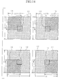
- Figure 14 is a schematic diagram showing a template 13 to be used for obtaining motion vectors and a target search area 12 to search for motion vectors.
- the motion vector search apparatus is required to have four times the computational power compared with the case such as possible values of motion vector are in a range of [-4 ⁇ +3] pixels in the horizontal and vertical directions, respectively. If the total area is divided in four areas 14, 15, 16, 17 whose edges are overlapped, and if the four areas are searched by four separate apparatuses, then four apparatuses, each having a capability of computing sum of an absolute value of differences in 64 areas, can compute sum of an absolute value of differences in 256 areas.
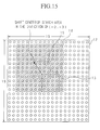
- the fourth conventional technique is based on that it would be possible to estimate the movement of the overall image with some probability, by examining the distribution of motion vectors that have been encoded in the past, because moving images on the screen are continual. In such a case, the center of search can be shifted towards the estimated movement direction. This method will be explained with reference to Figure 15.
- Figure 15 shows a process of searching by anticipating that the overall image movement will be in the direction of (-2, -3) are searched, so that areas centered about a pixel block 19 corresponding to a motion vector (-2, -3).
- searches for a motion vector will be conducted in a search area over a range of [-6 ⁇ +1] horizontal and [-7 ⁇ 0] vertical in relation to a reference pixel block 13.
- the search area 18 is the same as searching an area over a range of [-4 ⁇ +3] in horizontal and vertical directions.
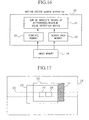
- Data on the template and search area are stored in an image memory 24 external to the motion vector search apparatus 20, and are transferred to template memory 22 and search area memory 23 in the apparatus 20, when they are needed for movement detection, and they are forwarded to a processing device 21 for computing a sum of the absolute values of differences and a minimum detected value.
- internal pixel transfer rate is high within the motion vector search apparatus 20, i.e., between the template memory 22 and the processing device 21 and between search area memory 23 and the processing device 21, but external transfer rate is slow, i.e., between the template memory 22 and image memory 24, and between search area memory 23 and image memory 24.
- an image is divided in the vertical direction into so-called slices, having the same size vertically as a template to be used.
- a slice is further divided in the horizontal direction into the template size. Encoding is performed from the top slice to the bottom slice in an image, and within each slice, encoding is performed from a left template to a right template successively. Therefore, there is considerable duplication of search areas between two adjacent templates.
- search areas for the templates 27, 28 in a slice 26 shown in Figure 17 are respective areas 29, 30, and when the detection process for a motion vector for template 27 is finished, all the pixels in the search area 29 are stored in the search area memory 23 shown in Figure 16. Subsequent to detection of motion vectors using template 27, suppose that motion vector searches using template 28 is performed and that pixels from the newly searched area 31 are transferred to the memory, all the pixels in the search area 30 for the template 28 will be memorized in the search area memory 23. In other words, if searches are conducted successively from left to right templates, there is no need to transfer all the pixels in the respective search areas of individual templates from the image memory 24 to search area memory 23, but to transfer only those pixels in the search area that are not duplicated by the left adjoining template.
- the fifth technique explained above is quite compatible with the fourth technique. This is because, when all the search areas of the templates contained in a slice are shifted by the same amount, the fifth technique can be applied easily.
- the fourth technique developed to increase the search area while keeping the cost low by utilizing historical estimation of motion vectors can present problems when the movement of currently encoded images suddenly changes, resulting that a motion vector could not be detected in narrow search areas. If a vector is unable to be found in any narrow areas, an amount of shift to be used in the subsequent searches cannot be determined. For example, after a scene change, if the video images consist of images whose motion vectors exceed the narrow area, then, even if the images are moving in the same direction at the same speed, the initial amount of pixels to be shifted cannot be determined, resulting that no subsequent movement can be estimated.
- the same shift is applied to the overall image so that if there is a different type of movement within the image, the technique is not applicable.
- the support side of the pendulum moves slowly while images closer to the tip of the pendulum will move faster.
- the background is stationary while the train moves horizontally in a given direction. In such images, if it is desired to detect motion vectors in as small a search area as possible, the search area must be shifted by different pixel amounts even within one image.
- the object has been achieved in an apparatus designed especially for a method comprising the steps of: 1) searching in a wide area and obtaining a reference vector to indicate an overall image movement; 2) searching in narrow areas centered about the reference vector for every template in a reference image that produced the reference vector, and obtaining a displacement vector in relation to the reference vector for each template; and 3) summing the reference vector and the displacement vector for each template, and assigning a computed result as a motion vector for a respective template.
- the object has also been achieved in another version of the apparatus especially designed for another method, comprising the steps of: 1) evaluating, in step 1, a movement of a whole template group containing a specific number of templates, and outputting a detected movement when an overall image movement of a whole template group is detected, and outputting a no-detection indicator when an overall image movement is not detected; 2) shifting, in step 2, a search center of a next template group according to the detected movement when the overall image movement is detected; and 3) assigning a specific motion vector to a center block in a search area to be searched by a next template group when the overall image movement is not detected.
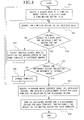
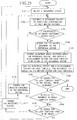
- Figure 1 is a block diagram of an example of the configuration of the motion vector search apparatus in the first to fourth variations of Embodiment 1.
- FIG. 2 is a flowchart showing the processing steps in Embodiment 1-1.
- Figure 3 is an illustration of the motion vectors in Embodiment 1-2.
- Figure 4 is a flowchart showing the processing steps in Embodiment 1-2.
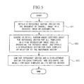
- FIG. 5 is a flowchart showing the processing steps in Embodiment 1-3.
- FIG. 6 is a flowchart showing the processing steps in Embodiment 1-4.
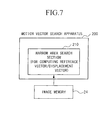
- Figure 7 is a block diagram of an example of the configuration of the motion vector search apparatus in Embodiment 1-5 and Embodiment 1-6.
- FIG. 8 is a flowchart showing the processing steps in Embodiment 1-5.
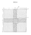
- Figure 9 is a schematic illustration of the search method in Embodiment 1-5.
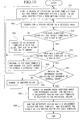
- Figure 10 is a flowchart showing the processing steps in Embodiment 1-6.
- Figure 11 is a schematic illustration of a conventional motion vector search technique.
- Figure 12 is a schematic illustration of a conventional motion vector search technique.
- Figure 13 is a schematic illustration of a conventional motion vector search technique.
- Figure 14 is a schematic illustration of a conventional motion vector search technique.
- Figure 15 is a schematic illustration of a conventional motion vector search technique.
- Figure 16 is a block diagram of a typical configuration of conventional motion vector search apparatuses.
- Figure 17 is a schematic illustration of the conventional techniques.
- Figure 18 is an example of the configuration of the motion vector search apparatus in Embodiment 2.
- Figure 19 is a schematic illustration of Embodiment 2.
- Figure 20 is a flowchart showing the processing steps in Embodiment 2-1.
- Figure 21 is a flowchart showing the processing steps in Embodiment 2-2.
- FIG 22 is a flowchart showing the processing steps in Embodiment 2-3.
- Figure 23 is a flowchart showing the processing steps in Embodiment 2-4.
- Figure 24 is a flowchart showing the processing steps in Embodiment 2-5.
- FIG. 25 is a flowchart showing the processing steps in Embodiment 2-6.
- Figure 26 is an illustration of telescopic search technique.
- a motion vector of an overall target image is obtained by a suitable method, and this vector is chosen as the reference vector to indicate the movement of the overall image.
- Examples of the method for determining the overall image movement is either to obtain motion vectors in a wide search area, using several templates in the target image, or carry out searches in a reduced image produced by sub-sampling.
- narrow search areas centered about the reference vector are selected for each template in the target image, and a displacement vector in a narrow search area is obtained.
- a motion vector for a template is obtained as a sum of the obtained displacement vector and the reference vector. This step is carried out for all the templates in the target image.
- a template group containing more than one template is selected. If a motion vector for the template group can be determined using a motion vector for each template in the template group, the shift location of the search center for a next template group is established according to the motion vector for the previous whole template group of which a motion vector has been determined. If, on the other hand, a motion vector for the template group cannot be established, the next search area will be shifted to a different location for the next template group with respect to the shift location used for the previous template group of which a motion vector has not been established.
- Embodiments 1-1 to 1-6 are based on the first method and apparatus and Embodiments 2-1 to 2-7 are based on the second method and apparatus.
- the first search method and apparatus will be presented in the following.
- Figure 1 is a block diagram of the configuration of the apparatus in Embodiment 1-1.
- the motion vector search apparatus 100 is comprised by a wide area search section 110 for determining the reference vector; and a narrow area search section 120 for determining a displacement vector.
- the reference vector in the first method refers to a motion vector of a target image that indicates the movement of the overall image.
- a displacement vector refers to a motion vector that each template in the target image must take to reach the location indicated by the reference vector.
- FIG. 2 is a flowchart of the processing steps in Embodiment 1-1.
- a wide area is searched using the wide area search section 110 to determine the reference vector to indicate the movement of the overall target image (step S1).
- the wide area search section 110 obtains motion vectors of a number of templates in the target image that indicate individual movements over a wide range in the search area. And, a motion vector of the overall target image is determined in relation to a comparison image, using more than one-motion vectors thus obtained. Clearly, if the computational power of the wide area search section 110 is sufficiently high, motion vectors can be determined for all the templates in the target image. Details of the action of the wide area search section 110 will be explained in Embodiments 1-2 ⁇ 1-4.
- a wide area or "a wide range of search areas” means a search area which is larger than what is normally selected as a search area.
- the image size in one frame for digitized NTSC signals is 720 pixels x 480 lines.
- the size of templates in the image (generally referred to as macroblock) is 16 pixels x 16 lines.
- the search area is generally specified within an area described by ⁇ 32 pixels horizontal and ⁇ 32 pixels vertical that a macroblock can be shifted.
- "a wide area” or "a wide range of search areas" in the present invention refers to an area described by ⁇ 100 pixels horizontal and ⁇ 50 pixels vertical.
- the image size in one frame of 1080I format of HDTV is 1920 pixels x 1080 lines.
- the size of macroblock in the image is also 16 pixels x 16 lines.
- "a wide area” or “a wide range of search areas” in the present invention refers to an area described by ⁇ 200 pixels horizontal and ⁇ 100 pixels vertical.
- selecting a larger value for the search area than one specified in normal conventional methods means that the present method is applicable to images containing fast moving objects, that is, large motion vectors for templates. It also means that a most suitable motion vector can be chosen as the reference vector.
- step S2 searches are made in narrow areas of all the templates in the target image centered about the reference vector, and a displacement vector in relation to the reference vector is obtained for each template (step S2), and a motion vector for each template is obtained by summing the reference vector and a respective displacement vector (step S3).
- the narrow area search section 120 selects a template A to search for a motion vector in a narrow area described by shifting the reference vector, as explained earlier using Figure 15.
- the narrow area search section 120 obtains a motion vector (in this case, a displacement vector) using the exhaustive search method explained earlier with reference to Figures 11 and 12.
- the narrow area search section 120 carries out searches using each template in the target image to determine a respective displacement vector, thus completing step S2.
- the narrow area search section 120 sums a displacement vector and the reference vector for each template to obtain its motion vector in the target image, thereby completing step S3.
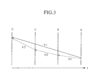
- Figure 3 shows an illustration for the motion vector in Embodiment 2-1.
- Moving images are formed by several contiguous image frames, and in video encoding, it is sometimes necessary to obtain a motion vector of an image several frames back.
- Figure 3 shows four contiguous images A, B, C and D.
- a motion vector Vt indicates the movement of image D based on the reference image, which is image A in this case. Normally, images are two-dimensional, but in this case, explanation is given in terms of one-dimensional image, for simplicity.
- a vector V1 is a vector to show the movement of image B based on image A.
- Figure 4 shows a flowchart for the processing steps in Embodiment 1-2 using the same apparatus as in Embodiment 1-1.
- the wide area search section 110 carries out separate searches to obtain V1, V2, V3 (steps S11 ⁇ S13) and sums V1, V2, V3 to obtain the reference vector Vt of image D based on image A (step S14).
- the wide area search section 110 performs the following steps.
- the wide area search section 110 performs these steps in steps S11, S12, S13.
- Steps S11 ⁇ S14 in Figure 4 indicate the actual processing steps involved in step S1 shown in Figure 2.
- the narrow area search section 120 searches in narrow areas, centered about the reference vector, for each templates in image D based on image A, and a displacement vector for each template is obtained in relation to the reference vector for all the templates (step S15). Then, a motion vector is obtained for each template by summing the reference vector and a respective displacement vector (step S16).
- Steps S15, S16 perform the same processing as steps S2, S3 shown in Figure 2.
- Figure 5 shows a flowchart for the processing steps in Embodiment 1-3 using the same apparatus as in Embodiment 1-1 shown in Figure 1.
- the reference vector is obtained in a reduced image produced by sub-sampling a high resolution image directly using the wide area search section 110, or by sub-sampling a reduced image produced by converting the high resolution image through a low-pass filter (step S21).
- step S21 Details of step S21 are as follows.
- step S21 relates to specific processing steps in step S1 shown in Figure 2.
- the narrow area search section 120 searches narrow areas centered about the reference vector in detail using each template, in the high resolution image (used in preparing the low resolution image), thus obtaining a displacement vector for each template (steps S22). A sum of the displacement vector and the reference vector is obtained for each template, and the resulting values are used as the motion vector of the respective template (step S23).
- Steps S22, S23 carry out same processing as steps S2, S3 shown in Figure 2.
- the reference vector is obtained using the wide area search section 110 on a reduced image, therefore, the cost of searching in a wide area can be suppressed.
- the wide area search section 110 can apply step S21 in steps S11, S12, S13 to obtain motion vectors V1, V2, V3 shown in Figure 4.
- Figure 6 shows a flowchart for the processing steps in Embodiment 1-4 using the same apparatus as in Embodiment 1-1 shown in Figure 1.
- the wide area search section 110 carries out searches using a lesser number of templates than the total number of templates needed to determine the movement of the overall target image, and obtains the reference vector indicating the movement of the overall target image (step S31 ⁇ S33).
- the wide area search section 110 specifies a wide search area for the selected template in the comparison image, and obtains a motion vector for this template.
- any one of the first to fourth conventional methods can be used for obtaining a motion vector (step S31).
- the section 110 determines whether the reference vector can be obtained by checking whether or not all the processing steps have been completed for all the selected templates (step S32). If there are unprocessed templates remaining, a next template to be processed is selected from the unprocessed templates (step S33).
- the reference vector is calculated as follows.
- All sums of the absolute values of differences or sums of squares of the differences of the computed motion vectors are checked to find out whether all the values are smaller than or equal to the pre-determined threshold value, if they are, then it is decided that the reference vector is an average value or a center value of the computed motion vectors.
- steps S31 ⁇ S33 relate to specific processing steps in step S1 shown in Figure 2.
- the narrow area search section 120 searches the narrow areas centered about the reference vector for all the templates used to determine respective displacement vectors, and obtains a sum of the reference vector and the displacement vector for each template, the result becomes the motion vector for each template (step S35).
- Steps S34, 35 carry out same processing as steps S2, S3 shown in Figure 2.
- the wide area search section 110 uses only a small number of templates relative to the total number of templates in one image, thereby suppressing the cost for searching the wide area.
- the number of templates required to determine the movement of the overall image is pre-selected depending on the image type. For example, when the overall scene is moving in a given direction, only one template is needed to determine the movement of the overall image. If the movements are unclear, and if it is required to know if there is a movement direction, a total of five areas, a center area plus four corners of the image is needed to be examined.
- the number of templates required to determine the movement of the overall image can be determined statistically so that the final results contain minimum errors.
- the wide area search section 110 can obtain motion vectors V1, V2, V3 by applying steps S31 ⁇ S33 to steps S11, S12, S13.
- Figure 7 shows a block diagram of the configuration of the apparatus in Embodiment 1-5.
- the motion vector search apparatus 200 is comprised only by a narrow area search section 210.
- the reference vector and displacement vectors are obtained by time-sharing the use of the narrow area search section 210.
- FIG. 8 shows a flowchart of the processing steps in Embodiment 1-5.
- a plurality of narrow areas are successively searched until the overall wide area has been searched to obtain a motion vector in a wide area.
- four narrow areas 14, 15, 16, 17 shown in Figure 14 are sequentially searched to obtain a motion vector in the wide area 12.
- a search area is selected by shifting the center of search area of the chosen template from the location of the zero motion vector (0, 0) to a given location (step S41).
- a motion vector in the selected area is searched (step S42). Until the search of the overall wide area is completed and a motion vector for the chosen template is determined (step S43), the same chosen template is used repeatedly by varying the amount of shift of the search area center (step S44).
- step S45 the reference vector indicating the movement of the overall image is obtained (step S45) by changing the chosen template for all the number of templates (step S46) required to know the movement of the overall image.
- the narrow area search section 210 selects a search area 14 to be search by template 13 (step S41).
- a motion vector in the search area 14 is obtained by comparing template 13 with the search area 14 (step S42).
- step S43 it is checked whether or not searches of the search areas 14, 15, 16, 17 are finished, i.e., searches in a wide range of search areas 12 are finished and the motion vector for the template currently being processed has been obtained.
- step S44 the next search area (search area 15, for example) is selected (step S44), and the process proceeds to step S42.
- step S43 When searches of all the search areas 14, 15, 16, 17 are finished (yes in step S43), a motion vector for the template 13 for the wide search area 12 is obtained. At this point, it is checked to find out whether searches using all the templates are finished and whether the reference vector can be obtained (step S45). If the results of step S45 shows that searches by all the selected templates are not finished, an unprocessed template is selected from the pre-selected templates (step S46), and the process returns to step S41.
- the calculation method for obtaining the reference vector when searches are completed by all the pre-chosen templates, is the same as the method explained in step S32 shown in Figure 6.
- the reference vector has thus been obtained.
- step S47 When the reference vector to indicate the movement of the overall image is obtained, narrow areas centered about the reference vector are searched in detail using all the templates, contained in the template group in the image, to obtain a displacement vector in relation to a reference vector for each template (step S47).
- a displacement vector is determined for each template, the reference vector and the displacement vector are summed, the result is assigned as a motion vector for respective templates (step S48).
- Steps S47, S48 perform same processing as steps S2, S3 shown in Figure 2.
- steps S41 ⁇ S46 show details of processing in step S1 shown in Figure 2.
- the motion vector search apparatus 100 may obtain V1, V2, V3 by applying the steps S41 ⁇ S46 to steps S11, S12, S13 shown in Figure 4.
- a time interval required for searches represents a sum of the time intervals required to obtain a displacement vector and the reference vector, and search durations are longer than those in Embodiment 1-1 ⁇ 1-4.
- the time intervals, for steps S41 ⁇ S46 in the flowchart shown in Figure 8 required to determine the reference vector are shorter compared with the time intervals required to obtain displacement vectors in step S47, and the reference vector can be obtained with only a small increase in search time duration.
- search area memory As the search area is widened, however, when searching for motion vectors, there is a possibility of insufficient pixel transferring capacity for the search area memory and the image memory 24, even if it is configured in such a way that the search area memory stored in the external image memory 24 is read into the search area memory (not shown) in the motion vector search apparatus 200.
- Figure 9 shows a schematic illustration of Embodiment 1-5, and the reference numeral 46 refers to the overlapped areas of the four narrow areas 14, 15, 16, 17.
- the reference numeral 46 refers to the overlapped areas of the four narrow areas 14, 15, 16, 17.
- few pixels belong to more than two search areas of the four narrow areas 14, 15, 16, 17. Therefore, in the configuration of Embodiment 1-5, even if the apparatus is configured such that the search areas stored in an external memory 24 is to be read into the search area memory 23 in the apparatus 200 when searching for a motion vector, the number of pixels to be transferred from the image memory 24 to the search area memory 23, when the search area is being changed, decreases only slightly. As the search area is widened, the proportion of pixels in the overlapped areas to the total number of pixels in the total search area will decrease so that the lack of sufficient pixel transfer capacity between the search area memory and image memory 24 will produce a more severe effect.
- Figure 10 shows a flowchart of the processing steps in Embodiment 1-6 using the same apparatus as in Embodiment 1-5 shown in Figure 7.
- the fifth conventional technique is used to determine the reference vector, to reduce the volume of pixels transferred between the search area memory 23 and the image memory 24. That is, search areas are described by shifting a given number of pixels from the zero motion vector (0, 0), for all the target templates in a specific slice of a target image, and a search is made starting from the template located at the edge of the image. Next, after finishing searches using the target templates in the specific slice, the center of search is shifted by the given number of pixels from the zero motion vector (0, 0) to select another search area, and searches are conducted in the same manner. This process is repeated in a wide area, and motion vectors in the wide area are obtained using the target templates in another slice. The process is repeated for other slices, and the slices required to determine the movement of the overall image are searched, thereby obtaining the reference vector to indicate the overall image movement.
- step S51 select an edge template from the target templates within a slice, and define the search area by shifting the search center from the zero motion vector (0, 0) (step S51), and search for the motion vector (step S52) in the described search area until respective motion vectors are obtained for all the target templates (step S54).
- step S54 This process is repeated by searching in the adjacent slice for all the target templates in the target slice (step S53). However, in step S54, the amount of shift of the search center is not adjusted.
- step S56 When motion vectors are determined for respective target templates in a target slice, same process is repeated by changing to an edge template within the target slice (step S56) until the wide search is finished within the target slice and a motion vector is determined for each target template (step S55), by returning to step S52. In step S56, the amount of shift of the search center is adjusted.
- step S58 The above processing is repeated (step S58) until the required number of templates, to determine the movement of the overall image, have been searched and the reference vector to indicate the movement of the overall image is obtained (step S57).
- the narrow area search section 210 selects a shifted search area in relation to the edge template 27 (for example, an area corresponding to search area 14 in Figure 14) from the target templates contained in slice 26 (in this case, templates 27, 28) (step S51).
- step S52 by comparing the selected search area and template 27, a motion vector is obtained (step S52).
- step S53 it checks whether searches in areas specified by the same shift amount are finished for all the target templates 27, 28 in the slice 26 being processed.
- step S54 a search area is described by the same shift amount (for example, a search area 14 in Figure 14) and the process returns to step S52.
- step S53 When searches are finished for the same shift area by the two target templates (yes, in step S53), it checks whether the searches in all areas (for example, four areas 14, 15, 16, 17 in Figure 14) are finished (step S56).
- a search area specified by a different shift amount is selected for the edge template 27 from all the templates in slice 26 (for example, a search area 15 in Figure 14) (step S56), and the process returns to step S52.
- step S55 motion vectors are obtained for the respective target templates in the wide search area (area 12 in Figure 14).
- step S57 When there are unfinished slices (step S57), another unprocessed slice is selected (step S58), and the process returns to step S52.
- step S57 when all the target slices are processed, is the same as the method explained in step S32 in Figure 6.
- the reference vector has thus been determined.
- step S59 When the reference vector to indicate the movement of the overall image is obtained, narrow areas centered about the reference vector are searched in detail using all the templates, contained in the template group in the image, for obtaining the reference vector, and displacement vectors are obtained for each template (step S59). When a displacement vector is determined for each template, the reference vector and the displacement vectors are summed, and the results are assigned as the motion vectors for respective templates (step S60).
- Steps S59, S60 perform same processing steps as steps S2, S3 shown in Figure 2.
- steps S51 ⁇ S58 represent the specific steps in step S1 shown in Figure 2. Also, in Embodiment 1-2, motion vector search apparatus 100 can obtain V1, V2, V3 by applying steps S51 ⁇ 58 to processing steps S11, S12, S13 shown in Figure 4.
- motion vectors were determined for all the templates contained in slices selected for obtaining the-reference vector, but it is not necessary to limit to this procedure.
- contiguous templates which are a part of templates in the target slice, may be processed.
- motion vector searches are carried out under highly effective manner of accessing the memories.
- motion vector distribution obtained in past searches may be analyzed to estimate the first reference vector to indicate the movement of the overall image, and at the same time, the second reference vector indicating the movement of the overall current target image is obtained according to the present technique.
- searches are made in detail in the narrow areas centered about the first reference vector for all the templates in the target image and also in the narrow areas centered about the second reference vector for all the templates in the target image, so as to determine the displacement vector which has minimum sum of absolute value of differences in the displacement vectors relating to the first and second reference vectors.
- Embodiments 1-1 ⁇ 1-6 has an advantage that the search range can be expanded without increasing the cost of the apparatus and that a movement can always be detected when the movement is within the expanded area.
- the exhaustive search method known to be the most sensitive method cannot avoid some erroneous detection.
- the search area is expanded to improve the image quality of large movements, disparity among the motion vectors increases because of an increase in erroneous detection. Therefore, the present method provides an additional advantage that, when the reference vector to indicate the movement of the overall image is detected first, as explained in the present invention, and searches for motion vectors are made only in its vicinity, disparity among the motion vectors due to erroneous detection can be minimized, thus resulting in improving the image quality.
- Figure 18 shows a block diagram of a second motion vector search apparatus.
- the apparatus 100 is comprised by a motion vector search section 130, which is able to search a given search area of a constant area size.
- the motion vector search section 130 includes a group motion detection section 131 to evaluate a movement of a given number of templates (termed a template group hereinbelow), and a search area shift section 132.
- the group motion detection section 131 evaluates a movement of whole template group using a pre-determined evaluation function, and when a movement of the target template group is detected, the search area shift section 132 shifts the search area for a next template group according to the detected movement.
- the shift amount is termed the reference vector in the following.
- Figure 19 shows an example slice represented by a template group.
- One slice contains ten templates, and ten motion vectors are analyzed to obtain the movement of the slice 140, and this movement is used as the reference vector to decide where to shift the search area next.
- An example of such a function would provide a sum of absolute values of differences as the reference for obtaining a motion vector for each template group, and when the sum for each template in the template group is less than a pre-determined threshold value, a motion vector that appears most frequently is chosen as the movement of the template group.
- two kinds of motion vectors are found for the ten templates, one kind is a motion vector 142 and other kind is a motion vector 143. It can be seen that the motion vector 142 appears seven times but the motion vector 143 appears three times. In this case, the output will be the motion vector 142 as the movement 144 for slice 140 (whole template group).
- the example gives only two kinds for simplicity, but normally, individual vectors have slightly different sizes so that it would be necessary to analyze the distribution pattern of the motion vectors by using histograms and the like.
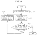
- FIG 20 is a flowchart of the processing steps in Embodiment 2-1.
- the group motion detection section 130 selects a specific reference vector, for example the zero motion vector (0, 0) (step S110).
- the motion vector search section 130 selects a search conducted in areas centered about a block of the zero motion vector (0, 0) (step S111), and the motion vector for the template group detected according to the forgoing function is selected as the reference vector for the next template group (step S113). Subsequently, searches are continued using the motion vector for the current template group as the reference vector for the next template group, until the last template group in the overall image sequence is completed (step S112).
- the motion vector search section 130 selects a specific reference vector, for example the reference vector may be zero motion vector (0, 0) (step S110).
- the motion vector search section 130 processes the topmost (first) template group contained in the first image in the image sequence, by determining a motion vector for each template in the template group. This process will be explained chronologically in the following.
- step S111 The above steps complete the processing in step S111.
- the motion vector search section 130 checks whether the bottom template group in the last image in the image sequence has been processed (step S112), and if the bottom template group in the last image is finished, the processing is completed.
- the group motion detection section 131 obtains a motion vector for the template group according to the evaluation function explained in Figure 19, using the motion vectors for individual templates in the group obtained in step S111. And, the group motion detection section 131 chooses the motion vector for the template group as the reference vector for a next template group (step S113) and the process returns to step S111.
- step S111 the motion vector search section 130 processes the next template group located at the top of the first image contained in the image sequence.
- the order of processing the template groups is from left to right and top to bottom, in view of memory access efficiency when processing according to reference standards of MPEG, for example.
- the motion vector search apparatus chooses a motion vector for a preceding template group as the reference vector for searching a motion vector for each template in the following template group.
- step S111 when each template contained in a template group searches for a motion vector (step S111), an actual motion vector for the target template (equivalent to reference vector + displacement vector described in Embodiment 1-1), is obtained and using the actual motion vectors of all the target templates, a reference vector for the template group is calculated. This procedure is followed in all the following embodiments, Embodiments 2-1 ⁇ 2-5.
- Embodiment 2-2 when a movement of the whole template group is detected, the motion vector for the whole template group is output, but when a movement is not detected, a function is provided that give an alert that "movement is not detected".
- “Movement is detected” includes a case of no-motion, i.e., zero motion vector (0, 0), and "movement is not detected” means that a block to match the target template is not found in the search area.
- An example of such evaluation functions would provide a sum of the absolute values of differences of the motion vectors as the reference for obtaining a motion vector for each template group, and when the sum for all templates is less than or equal to a pre-determined threshold value, a motion vector that appears most frequently is chosen as the movement of the template group. If there is even one template having sum of the absolute value of the differences exceeding the threshold value, the function outputs "movement is not detected".
- Embodiment 2-2 when a movement of a template group is not detected, the amount of shift in the search area for the next template group is adjusted, and a new reference vector, for example reference vector (0, 0) is selected.
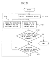
- FIG 21 shows a flowchart for processing steps in Embodiment 2-2.
- a specific reference vector for example reference vector (0, 0)
- searches are conducted in search areas centered about a block of zero motion vector (0, 0) (step S121). So long as movement is not detected, searches are continued in the search areas centered about the block of zero motion vector (0, 0).
- this motion vector is assigned as the reference vector for the next template group (step S124).
- step S122 searches are continued until the last template group is processed (step S122), by assigning a preceding motion vector as the reference vector for the next template group when movement is detected, and by resetting the reference vector for the next template group to the reference vector (0, 0) when movement is not detected.
- steps S120 ⁇ S121 and S124 correspond to steps S110 ⁇ S113, respectively.
- step S123 is newly added in Figure 20, in which the group motion detection section 131 determines a motion vector according to the foregoing evaluation function.
- Embodiment 2-3 when a movement of a template group cannot be detected, searches are continued until a template group that can detect a movement is found by altering the reference vector for each subsequent template group so as to search in a different range of search areas.
- a plurality of template groups searching for motion vectors means that search can be conducted in a wide search area.
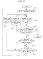
- Figure 22 shows processing steps in Embodiment 2-3.
- a specific reference vector for example reference vector (0, 0) is selected (step S130), and searches are conducted in search areas centered about a block of zero motion vector (0, 0) (step S131).
- this motion vector is assigned as the reference vector for the next template group (step 134).
- a reference vector for the next template group is adjusted to a reference vector (x1, y1), excepting the reference vector (0, 0) (step S136), and searches are continued similarly for the next template group. If a movement of the whole template group is detected as a result of this search, searches are continued by assigning this motion vector as the reference vector for the next template group. If again a movement cannot be detected, the reference vector for the next template group is adjusted to a reference vector (x2, y2), excepting the vectors (0, 0) and (x1, y1), according to a pre-determined rule. If the processed template group is the last template group in the target image (step S135), the process returns to step S130, and a reference vector for the first processing template group in the next target image is reset to (0, 0).
- step S132 The above steps are repeated until the last template group in the overall image sequence is processed.
- steps S130 ⁇ S134 correspond to steps S120 ⁇ S124, respectively.
- steps S135, S136 are newly added to Figure 21. Further, in step S135, the motion vector search section 130 checks whether the current template group is the last template group in the image being processed, and if it is the last template group, the process returns to step S130 to continue processing of next image in the image sequence. On the other hand, if it is not the last template group, the motion vector search section 130 selects a different reference vector, in step S135, according to the rule described earlier.
- Embodiment 2-4 initially, a plurality of searches are executed in a wide range of search areas by selecting suitable search areas such as the center area in an image, in order to determine a motion vector for the overall image,. When a motion vector for a template group is detected, further search is executed by assigning this vector as the reference vector. If a motion vector is not detected, a specific vector, for example the reference vector (0, 0) is selected for further searching.
- the detected motion vector is assigned as the reference vector for the next template group to continue searching.
- a new wide area search is executed according to the following procedure. Before initiating a search for the next image, a plurality of searches are executed using a different reference vector in suitable search areas, such as the center area in the image, to detect a motion vector of the overall image, and selecting this motion vector as the initial value of the reference vector for the next image.
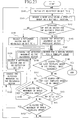
- FIG 23 is a flowchart for the processing steps in Embodiment 2-4.
- no- detection bit is initialized to 0, which indicates that a movement of the whole template group could not be detected in the target image in the image sequence (step S140).
- a plurality of searches for a motion vector is executed over a wide range of search areas by selecting a different reference vector for a template group located in an area suitable for searching a movement of the overall image, such as the center of an image (step S141).
- This search step for a motion vector for the whole template group is substantially the same as repeating the steps S120, S121 in Figure 21. However, there are two differences, one is to select different reference vectors successively in a process equivalent to step S120, according to a pre-determined rule, and the other is to change the location of template group successively in a process equivalent to step S121.
- step S142 When a motion vector is detected in this search (step S142), this motion vector is chosen as the reference vector (step S143), and the search is executed for a motion vector for the template group (step S145).
- a specific reference vector for example a reference vector (0, 0) is selected, and after no-detection bit is set to 1 (step S144), search is executed for a motion vector for the template group (step S145).
- step S142 judging criterion in step S142 is the same as that in step S123 in Figure 21.
- step S142 is processed by the group motion detection section 131, and selection of search area in steps S143, S144 is processed by the search area shift section 132. Other processing steps are carried out by the motion vector search section 130.
- step S148 detected movement is assigned as the reference vector for the next template group (step S149).
- a specific reference vector is selected, and no-detection bit is set to 1 (step S150), and search is continued for a motion vector for the template group (step S145).
- step S147 the process checks whether the no-detection bit is 1 (step S151), and if the no-detection bit is 1, it returns to step S140 to repeat the same steps for the next image. If the no-detection bit is 0, depending on whether or not the movement of the whole template group is detected (step S152), and if it is detected, the detected movement is assigned as the reference vector in step S153, and search for a motion vector for the template group is continued (step S145). If a motion vector for the whole template group cannot be detected, the process returns to step S140.
- steps S145, S146 correspond respectively to steps S131, S132.
- steps S148, S149 correspond respectively to steps S133, S134, and steps S152, S153 also correspond respectively to steps S133, S134.
- steps S147, S150 correspond respectively to steps S135, S136. However, step S150 also processes the no-detection bit.
- steps S140 ⁇ S144 correspond to processing in step S130 in Figure 22.
- the motion vector search section 130 uses a portion of the target image to obtain an initial reference vector in steps S140 ⁇ S144, and selects this reference vector.
- the motion vector search section 130 selects the reference vector detected in step S153 as the reference vector for the target image.
- Processing of each template group in the target image is carried out in steps S145 ⁇ S153.
- step S141 an example of a suitable location of a template group was illustrated by the center area in the target image. It may be considered that a central area is preferable for obtaining a motion vector for movement of an overall image, but the choice is not restricted to this location.
- step S141 for choosing a suitable template group the left edge template of the target image (the first template group in the image to be processed) contained in the upper-most slice in the target image may be chosen.
- the motion vector search section 130 pre-determines the motion vectors of each template in the template group in step S141, the first template group to be processed in step S145 will be the next template group to the template group processed in step S141.
- Such a procedure would shorten the processing effort, and can execute memory access more efficiently.
- steps S141 ⁇ S143 may be omitted, and step S144 may be used only to select a specific reference vector.
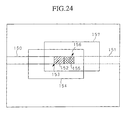
- Embodiment 2-5 is based on modifying Embodiment 2-1 ⁇ 2-4 to include all the templates within one slice in one common template group.
- a template group in this embodiment is comprised by one slice or a plurality of slices.
- the fifth conventional technique cannot be used when a search step is transferring from one template group to a next template group, causing transfer of extra pixels in the search area.
- left half templates and right half templates within the same slice are contained in different template groups, resulting that the reference vector for the template group 150 (left half templates) are different than the reference vector for the template group 151 (right half templates).
- the search area is 154 for the last template 152 of template group 150 and the search area is 157 for the first template 155 of template group 151.
- the search areas 154, 157 are offset as illustrated in the drawing, the fifth conventional technique cannot be applied, and almost all the pixels in the search area 157 must be transferred from the image memory 24 to search area memory 23 which was explained in Figure 16, causing the need for transfer of extra pixels.
- Embodiment 2-5 is configured so that all the templates within one slice is contained in a common group to avoid the problem discussed above.
- the slices are horizontal as shown in Figure 24.
- Embodiment 2-6 when a movement of the whole template group is detected, the detected movement is assigned as the reference vector, and when a movement of the whole template group cannot be detected, a reference vector is varied for each template group to search for a motion vector in different ranges of search areas, until a movement can be detected from subsequent template groups. However, before executing a search for a movement in the next template group, distribution of motion vectors of encoded video images is analyzed to estimate the movement of the next template group. Next, the probability of correctness of the estimated movement is evaluated, and if it is judged to be high, reference vector is changed to the estimated movement.
- Method that may be used to judge the correctness of estimated movement is to compare the movement of the detected template groups in the current image with the movement of the corresponding template groups in the immediate preceding image, and if they match, estimated movement is judged to be correct but, even if one template group exhibits a different behavior, the estimated movement is judged to be incorrect.
- FIG. 25 shows a flowchart of the processing steps in Embodiment 2-6.
- the motion vector detection section 130 selects a specific reference vector, for example the reference vector (0, 0) (step S161).
- the motion vector detection section 130 excepting the template groups contained in the first image in the image sequence to be processed, analyzes the distribution of motion vectors in the encoded past images before searching for movement of the template groups, so as to estimate a movement of the template group (step S162). Estimation method is as described above.
- the motion vector detection section 130 judges whether the probability of estimated movement being correct is high or low (step S163) using the method mentioned above, and if the probability is high, the reference vector is changed to the estimated movement (step S164).
- the motion vector detection section 130 judges that the estimated movement is in error, and skips step S164.
- the motion vector detection section 130 selects and searches narrow search areas centered about the reference vector to obtain a displacement vector within the search area for each of the templates contained in the template group (step S165).
- the motion vector detection section 130 calculates individual motion vectors by obtaining a sum of the reference vector and the individual displacement vectors obtained (step S166).
- the motion vector detection section 130 checks whether the processed template group is the last template group in the target image in the image sequence (step S167), and if it is the last template group, the process is completed.
- the group motion detection section 131 detects a movement of the whole template group using the individual motion vectors obtained in step S166, according to the method explained earlier (step S168). At this time, the group motion detection section 131 stores the data relating the detected motion vectors and the location of the template groups in memory (not shown), for the purpose of analyzing the motion vectors in step S162.
- step S168 When a movement of the whole template group is detected in step S168, the motion vector detection section 130 selects the motion as the reference vector for the next template group (step S170), and the process proceeds to step S162.
- the motion vector detection section 130 selects a reference vector for the next template group, according to a pre-determined rule, and a reference vector (x1,y1 ), excepting the reference vector which have been selected (step S171), is selected and the process proceeds to step S162. If again a movement could not be detected, a reference vector for a next template group is adjusted to a reference vector (x2, y2), excepting the vectors (0, 0) and (x1, y1) selected already according to a pre-determined rule. When the last template group in the target image is processed (step S169), the motion vector detection section 130 proceeds to step S161, and processing is executed on the next image in the image sequence.
- step S161 corresponds to step S130.
- Steps S165, S166 are steps included in step S131.
- Steps S167 ⁇ S171 correspond respectively to steps S132 ⁇ S136.
- steps S162 ⁇ S164 enable the motion vector detection section 130 to select reference vectors reflecting the motion vectors obtained from historical encoded video images.
- the following effect can be obtained.
- a train is moving in the bottom half of a scene, and the upper half is the background, their movements are different. So, a simple assigning of a motion vector for an immediate preceding template group as the reference vector for a next template group is not sufficient to describe the movement of template groups at the boundary between the background and the train. In such a case, motion vectors of the templates contained in the template groups cannot be detected with sufficient accuracy.
- selection of reference vectors are aided by the use of estimated reference vectors obtained from a distribution of motion vectors in historical encoded video images (step S162 ⁇ S164), therefore, these steps can be applied to the template groups in the boundary between the background and the train to obtain appropriate reference vectors.
- the result is a precision technique of detection of motion vectors for individual templates.
- all the templates within one slice are included in one common template group, as explained in Embodiment 2-5, so that motion vector searches are carried out under highly effective manner of memory access.
- Embodiment 2-7 includes a telescopic search capability in the motion vector search apparatus presented to this point. First, telescopic search will be explained.
- motion vectors are sometimes obtained from an image in several preceding images.
- a method used in such a case is to first obtain a motion vector between two adjoining images, and this motion vector is used as the initial value to obtain a motion vector for the succeeding adjoining image, and this process is repeated to obtain a motion vector between images separated over a long time interval.
- This method is termed the telescopic search method. Because movements between adjoining images are relatively small, telescopic search method enables to detect movements over a smaller search area relative to searching in two images separated by a long time interval.
- Telescopic search method will be explained with reference to a schematic diagram shown in Figure 26.
- Images 204, 205, 206 are three contiguous images (frames).
- the image 206 represents a current image
- the images 205 and 204 represent a one-frame preceding image and a two-frame preceding image, respectively.
- a rectangular block 201 is moved between the image (frames) 206, 205 with a moving vector mv1, and between the images 205, 204, the block 201 is moved with a moving vector mv2. Therefore, a moving vector between images 206, 204 is given by (mv1+mv2).
- a motion vector mv1 for a movement in image 206 to image 205 is obtained by using the block 201 in image 206 as the template and searching in search area 202 in image 205.
- the motion vector of the center of area 202 is given by (0, 0).
- the area 202 in image 204 is searched to obtain a motion vector mv2.
- the motion vector for the block 201 from image 206 to image 205 indicate that the motion vector of the center of area 202 in image 204 will be mv1.
- allowable ranges for the motion vector (mv1+mv2) are, respectively, -2a ⁇ mv1 x +mv2 x ⁇ 2a, and -2b ⁇ mv1 y +mv2 y ⁇ 2b. It can be seen that, in the telescopic search method, the farther apart the images are in time the larger the allowable area, in other words, allowable search area becomes larger. This is indicated in Figure 26 so that in image 205 separated from image 206 by one frame, search can be executed over an area 202, but in image 204 separated from image 206 by two frames, search can be executed over a larger area 203.
- a method of combining the telescopic method with the second conventional technique is found in, for example, "A real-time motion estimation and compensation LSI with wide search range for MPEG2 video encoding" by K. Suguri et. al., IEEE J.Solid-State Circuits, vol. 31, no. 11, pp.1733 ⁇ 1741, Nov. 1966.
- search areas that may be referenced in Embodiments 2-1 ⁇ 2-6 are stored in search area memory (not shown) of the motion vector search apparatus shown in Figure 18.
- search area memory not shown
- area 202 in image 205 and area 203 in image 204 shown in Figure 26 are stored in search area memory.
- Embodiments 2-1 ⁇ 2-6, the motion vector search apparatus used in these embodiments was not capable of executing the telescopic search method, when search area memory was made to store only the actual search areas in the search area memory.
- search area memory was made to store only the actual search areas in the search area memory.
- the potential search areas, that may be referenced were stored in the search area memory of the apparatus, it was possible to utilize the telescopic method to search for a motion vector in a restricted search area, having high probability, even though the potential area of finding a motion vector extends over a wide area.
- the second method of motion vector search method and apparatus enable to expand the search area without increasing the cost for the apparatus, and to ensure finding a motion vector if it exists within the expanded search area, and also enables to alter the amount of shifting a search area to reflect the result of searches over a portion of the search area.
- Embodiments 1-1 ⁇ 1-6, and Embodiments 2-1 ⁇ 2-7) for detecting motion vectors can be recorded as application programs in a computer-readable memory medium, and can be applied in solving problems of motion vector search, by using a computer system to read such programs.
- a computer system includes any operating systems (OS) and peripheral hardwares that are connected (remotely or directly) to the computer system.
- Computer-readable recording media include portable media such as floppy disks, opto-magnetic disks, ROM, CD-ROM, as well as fixed devices such as hard disks housed in computer systems.
- Computer-readable memory media further include short-term dynamic memories (transmission media inclusive of wave signals) used in transmitting applications through such means as networks such as Internet or telephone line network, as well as other short-term memories such as volatile memories used in servers and client computer systems.
- Application programs may perform a part of the described functions, or may be operated in conjunction with pre-recorded programs stored in computer systems to provide differential files (differential programs).
Landscapes
- Engineering & Computer Science (AREA)
- Multimedia (AREA)
- Signal Processing (AREA)
- Computer Vision & Pattern Recognition (AREA)
- Physics & Mathematics (AREA)
- General Physics & Mathematics (AREA)
- Theoretical Computer Science (AREA)
- Compression Or Coding Systems Of Tv Signals (AREA)
- Image Analysis (AREA)
Applications Claiming Priority (4)
| Application Number | Priority Date | Filing Date | Title |
|---|---|---|---|
| JP13628798 | 1998-05-19 | ||
| JP13628798 | 1998-05-19 | ||
| JP20262898 | 1998-07-17 | ||
| JP20262898 | 1998-07-17 |
Publications (3)
| Publication Number | Publication Date |
|---|---|
| EP0959626A2 true EP0959626A2 (de) | 1999-11-24 |
| EP0959626A3 EP0959626A3 (de) | 2005-06-22 |
| EP0959626B1 EP0959626B1 (de) | 2012-08-15 |
Family
ID=26469926
Family Applications (1)
| Application Number | Title | Priority Date | Filing Date |
|---|---|---|---|
| EP99401195A Expired - Lifetime EP0959626B1 (de) | 1998-05-19 | 1999-05-18 | Verfahren und Vorrichtung zur Bewegungsvektorermittlung |
Country Status (3)
| Country | Link |
|---|---|
| US (1) | US6380986B1 (de) |
| EP (1) | EP0959626B1 (de) |
| KR (1) | KR100325253B1 (de) |
Cited By (2)
| Publication number | Priority date | Publication date | Assignee | Title |
|---|---|---|---|---|
| GB2378345A (en) * | 2001-07-09 | 2003-02-05 | Samsung Electronics Co Ltd | Method for scanning a reference macroblock window in a search area |
| CN110225341A (zh) * | 2019-06-03 | 2019-09-10 | 中国科学技术大学 | 一种任务驱动的码流结构化图像编码方法 |
Families Citing this family (49)
| Publication number | Priority date | Publication date | Assignee | Title |
|---|---|---|---|---|
| JP3721867B2 (ja) * | 1999-07-07 | 2005-11-30 | 日本電気株式会社 | 映像表示装置及び表示方法 |
| US6970510B1 (en) * | 2000-04-25 | 2005-11-29 | Wee Susie J | Method for downstream editing of compressed video |
| US6973130B1 (en) | 2000-04-25 | 2005-12-06 | Wee Susie J | Compressed video signal including information for independently coded regions |
| US6501794B1 (en) * | 2000-05-22 | 2002-12-31 | Microsoft Corporate | System and related methods for analyzing compressed media content |
| US7327787B1 (en) * | 2000-11-20 | 2008-02-05 | Intel Corporation | Method and apparatus for motion estimation |
| US6687301B2 (en) * | 2001-03-19 | 2004-02-03 | Fulvio Moschetti | Method for block matching motion estimation in digital video sequences |
| US20020136302A1 (en) * | 2001-03-21 | 2002-09-26 | Naiqian Lu | Cascade window searching method and apparatus |
| US6987866B2 (en) * | 2001-06-05 | 2006-01-17 | Micron Technology, Inc. | Multi-modal motion estimation for video sequences |
| WO2003017833A1 (en) * | 2001-08-31 | 2003-03-06 | Jong-Won Park | Method and apparatus for a medical image processing system |
| JP2003153269A (ja) * | 2001-11-08 | 2003-05-23 | Mitsubishi Electric Corp | 動きベクトル検出装置、それを複数用いた動きベクトル検出システムおよび動きベクトル検出方法 |
| US20030103567A1 (en) * | 2001-12-03 | 2003-06-05 | Riemens Abraham Karel | Motion compensation and/or estimation |
| US7113644B2 (en) * | 2002-02-13 | 2006-09-26 | Matsushita Electric Industrial Co., Ltd. | Image coding apparatus and image coding method |
| US7180429B2 (en) * | 2002-02-14 | 2007-02-20 | Intel Corporation | Slow motion detection system |
| US7742525B1 (en) * | 2002-07-14 | 2010-06-22 | Apple Inc. | Adaptive motion estimation |
| US7239721B1 (en) * | 2002-07-14 | 2007-07-03 | Apple Inc. | Adaptive motion estimation |
| US7072399B2 (en) * | 2002-07-17 | 2006-07-04 | Lsi Logic Corporation | Motion estimation method and system for MPEG video streams |
| US7231090B2 (en) * | 2002-10-29 | 2007-06-12 | Winbond Electronics Corp. | Method for performing motion estimation with Walsh-Hadamard transform (WHT) |
| JP4003128B2 (ja) * | 2002-12-24 | 2007-11-07 | ソニー株式会社 | 画像データ処理装置および方法、記録媒体、並びにプログラム |
| JP4536325B2 (ja) * | 2003-02-04 | 2010-09-01 | ソニー株式会社 | 画像処理装置および方法、記録媒体、並びにプログラム |
| US7324596B2 (en) * | 2003-07-15 | 2008-01-29 | Lsi Logic Corporation | Low complexity block size decision for variable block size motion estimation |
| US7453940B2 (en) * | 2003-07-15 | 2008-11-18 | Lsi Corporation | High quality, low memory bandwidth motion estimation processor |
| US7319795B2 (en) | 2003-09-23 | 2008-01-15 | Broadcom Corporation | Application based adaptive encoding |
| US20050084135A1 (en) * | 2003-10-17 | 2005-04-21 | Mei Chen | Method and system for estimating displacement in a pair of images |
| KR100575578B1 (ko) * | 2003-11-13 | 2006-05-03 | 한국전자통신연구원 | 이동 단말 장치에서의 움직임 검출 방법 |
| US7602849B2 (en) * | 2003-11-17 | 2009-10-13 | Lsi Corporation | Adaptive reference picture selection based on inter-picture motion measurement |
| US7889792B2 (en) * | 2003-12-24 | 2011-02-15 | Apple Inc. | Method and system for video encoding using a variable number of B frames |
| JP2005223631A (ja) * | 2004-02-05 | 2005-08-18 | Sony Corp | データ処理装置およびその方法と符号化装置および復号装置 |
| US7869503B2 (en) * | 2004-02-06 | 2011-01-11 | Apple Inc. | Rate and quality controller for H.264/AVC video coder and scene analyzer therefor |
| US7986731B2 (en) | 2004-02-06 | 2011-07-26 | Apple Inc. | H.264/AVC coder incorporating rate and quality controller |
| US7492820B2 (en) | 2004-02-06 | 2009-02-17 | Apple Inc. | Rate control for video coder employing adaptive linear regression bits modeling |
| US7792188B2 (en) | 2004-06-27 | 2010-09-07 | Apple Inc. | Selecting encoding types and predictive modes for encoding video data |
| US8111752B2 (en) | 2004-06-27 | 2012-02-07 | Apple Inc. | Encoding mode pruning during video encoding |
| US20050286777A1 (en) * | 2004-06-27 | 2005-12-29 | Roger Kumar | Encoding and decoding images |
| JP4241709B2 (ja) * | 2005-10-11 | 2009-03-18 | ソニー株式会社 | 画像処理装置 |
| KR100778116B1 (ko) * | 2006-10-02 | 2007-11-21 | 삼성전자주식회사 | 움직임벡터 보정장치 및 보정방법 |
| US7907217B2 (en) * | 2006-10-31 | 2011-03-15 | Siemens Medical Solutions Usa, Inc. | Systems and methods of subtraction angiography utilizing motion prediction |
| KR100860690B1 (ko) * | 2007-01-26 | 2008-09-26 | 삼성전자주식회사 | 외부 메모리 액세스를 최소화하는 움직임 탐색 방법 및장치 |
| JP5080333B2 (ja) * | 2007-04-06 | 2012-11-21 | 本田技研工業株式会社 | 自律移動体のための物体認識装置 |
| CN101415122B (zh) * | 2007-10-15 | 2011-11-16 | 华为技术有限公司 | 一种帧间预测编解码方法及装置 |
| JP5268433B2 (ja) * | 2008-06-02 | 2013-08-21 | キヤノン株式会社 | 撮像装置、及び撮像装置の制御方法 |
| TW201001339A (en) * | 2008-06-25 | 2010-01-01 | Univ Nat Chiao Tung | Method of detecting moving object |
| TWI396116B (zh) * | 2009-12-18 | 2013-05-11 | Pixart Imaging Inc | 位移偵測裝置及方法 |
| KR101183781B1 (ko) * | 2009-12-22 | 2012-09-17 | 삼성전자주식회사 | 실시간 카메라 모션 추정을 이용한 물체 검출/추적 방법 및 단말 |
| US9092864B2 (en) * | 2010-11-30 | 2015-07-28 | Pixart Imaging Inc | Displacement detection apparatus and method |
| US8737685B2 (en) | 2011-04-25 | 2014-05-27 | Honeywell International Inc. | Systems and methods for detecting the movement of an object |
| US8582821B1 (en) | 2011-05-23 | 2013-11-12 | A9.Com, Inc. | Tracking objects between images |
| US20130021488A1 (en) * | 2011-07-20 | 2013-01-24 | Broadcom Corporation | Adjusting Image Capture Device Settings |
| US10210399B2 (en) | 2013-12-20 | 2019-02-19 | Magna Electronics Inc. | Vehicle vision system with image processing |
| US9986189B2 (en) | 2016-01-04 | 2018-05-29 | Samsung Electronics Co., Ltd. | Pixel sensors and imaging devices for providing multiple sub sample images within a single frame |
Family Cites Families (10)
| Publication number | Priority date | Publication date | Assignee | Title |
|---|---|---|---|---|
| JP2830183B2 (ja) | 1989-10-14 | 1998-12-02 | ソニー株式会社 | 動きベクトル検出装置及び動きベクトル検出方法 |
| JP2586686B2 (ja) | 1990-04-19 | 1997-03-05 | 日本電気株式会社 | 動画像の動き情報検出装置および動画像の動き補償フレーム間予測符号化装置 |
| US5210605A (en) * | 1991-06-11 | 1993-05-11 | Trustees Of Princeton University | Method and apparatus for determining motion vectors for image sequences |
| JPH05328333A (ja) | 1992-05-15 | 1993-12-10 | Toshiba Corp | 動きベクトル検出装置 |
| US5473379A (en) * | 1993-11-04 | 1995-12-05 | At&T Corp. | Method and apparatus for improving motion compensation in digital video coding |
| US5619268A (en) * | 1995-01-17 | 1997-04-08 | Graphics Communication Laboratories | Motion estimation method and apparatus for calculating a motion vector |
| JP3994445B2 (ja) * | 1995-12-05 | 2007-10-17 | ソニー株式会社 | 動きベクトル検出装置及び動きベクトル検出方法 |
| JPH09212649A (ja) | 1996-02-06 | 1997-08-15 | Nippon Telegr & Teleph Corp <Ntt> | 動き推定方法 |
| JP3019787B2 (ja) | 1996-09-20 | 2000-03-13 | 日本電気株式会社 | 動きベクトル検出装置 |
| JPH10262258A (ja) | 1997-03-19 | 1998-09-29 | Sony Corp | 画像符号化装置及び方法 |
-
1999
- 1999-05-11 KR KR1019990016758A patent/KR100325253B1/ko not_active Expired - Lifetime
- 1999-05-12 US US09/310,148 patent/US6380986B1/en not_active Expired - Lifetime
- 1999-05-18 EP EP99401195A patent/EP0959626B1/de not_active Expired - Lifetime
Non-Patent Citations (1)
| Title |
|---|
| K. SUGURI: "A real-time motion estimation and compensation LSI with wide search range for MPEG2 video encoding", IEEE J.SOLID-STATE CIRCUITS, vol. 31, no. 11, November 1966 (1966-11-01), pages 1733 - 1741 |
Cited By (4)
| Publication number | Priority date | Publication date | Assignee | Title |
|---|---|---|---|---|
| GB2378345A (en) * | 2001-07-09 | 2003-02-05 | Samsung Electronics Co Ltd | Method for scanning a reference macroblock window in a search area |
| GB2378345B (en) * | 2001-07-09 | 2004-03-03 | Samsung Electronics Co Ltd | Motion estimation apparatus and method for scanning a reference macroblock window in a search area |
| CN1297134C (zh) * | 2001-07-09 | 2007-01-24 | 三星电子株式会社 | 用于扫描搜索区内参考宏块窗口的运动估计装置和方法 |
| CN110225341A (zh) * | 2019-06-03 | 2019-09-10 | 中国科学技术大学 | 一种任务驱动的码流结构化图像编码方法 |
Also Published As
| Publication number | Publication date |
|---|---|
| US6380986B1 (en) | 2002-04-30 |
| KR19990088182A (ko) | 1999-12-27 |
| KR100325253B1 (ko) | 2002-03-04 |
| EP0959626A3 (de) | 2005-06-22 |
| EP0959626B1 (de) | 2012-08-15 |
Similar Documents
| Publication | Publication Date | Title |
|---|---|---|
| EP0959626A2 (de) | Verfahren und Vorrichtung zur Bewegungsvektorermittlung | |
| US7050502B2 (en) | Method and apparatus for motion vector detection and medium storing method program directed to the same | |
| JP5044568B2 (ja) | 予測誘導間引き探索を使用する動き推定 | |
| US6985527B2 (en) | Local constraints for motion matching | |
| KR100973429B1 (ko) | 배경 움직임 벡터 선택기, 업-변환 유닛, 이미지 처리 장치, 배경 움직임 벡터 선택 방법 및 컴퓨터 판독 가능한 기록 매체 | |
| EP1587032B1 (de) | Bildverarbeitungsvorrichtung und -Verfahren, Aufzeichnungsmedium und Programm | |
| US20030189980A1 (en) | Method and apparatus for motion estimation between video frames | |
| US20030063673A1 (en) | Motion estimation and/or compensation | |
| KR20050084442A (ko) | 세그먼트 기반 움직임 추정 | |
| US20050180506A1 (en) | Unit for and method of estimating a current motion vector | |
| CN101589622B (zh) | 使用两种匹配判据的运动估计和场景变换检测 | |
| JP4213035B2 (ja) | オクルージョン領域を検出するオクルージョン検出器および方法 | |
| US20060098886A1 (en) | Efficient predictive image parameter estimation | |
| KR101141467B1 (ko) | 화상 처리 장치 및 방법, 및 기록 매체 | |
| US6912296B2 (en) | Motion estimation method | |
| US20050195324A1 (en) | Method of converting frame rate of video signal based on motion compensation | |
| US7881500B2 (en) | Motion estimation with video mode detection | |
| JP2009533887A (ja) | 動きベクトル場修正装置及び方法 | |
| KR100451184B1 (ko) | 모션 벡터 탐색 방법 | |
| JP3335137B2 (ja) | 動きベクトル探索方法、動きベクトル探索装置および動きベクトル探索プログラムを記録した記録媒体 | |
| KR20030024354A (ko) | 능동 카메라 환경에서의 고속 움직임 검출을 위한 배경보상 장치 및 방법 | |
| JPH08242454A (ja) | グローバル動きパラメタ検出方法 | |
| JP2001028754A (ja) | 動きベクトル検出方法 | |
| JP2743763B2 (ja) | 動画像の動き推定方法 |
Legal Events
| Date | Code | Title | Description |
|---|---|---|---|
| PUAI | Public reference made under article 153(3) epc to a published international application that has entered the european phase |
Free format text: ORIGINAL CODE: 0009012 |
|
| AK | Designated contracting states |
Kind code of ref document: A2 Designated state(s): AT BE CH CY DE DK ES FI FR GB GR IE IT LI LU MC NL PT SE |
|
| AX | Request for extension of the european patent |
Free format text: AL;LT;LV;MK;RO;SI |
|
| PUAL | Search report despatched |
Free format text: ORIGINAL CODE: 0009013 |
|
| AK | Designated contracting states |
Kind code of ref document: A3 Designated state(s): AT BE CH CY DE DK ES FI FR GB GR IE IT LI LU MC NL PT SE |
|
| AX | Request for extension of the european patent |
Extension state: AL LT LV MK RO SI |
|
| 17P | Request for examination filed |
Effective date: 20050912 |
|
| AKX | Designation fees paid |
Designated state(s): FR NL |
|
| REG | Reference to a national code |
Ref country code: DE Ref legal event code: 8566 |
|
| 17Q | First examination report despatched |
Effective date: 20080404 |
|
| GRAP | Despatch of communication of intention to grant a patent |
Free format text: ORIGINAL CODE: EPIDOSNIGR1 |
|
| GRAS | Grant fee paid |
Free format text: ORIGINAL CODE: EPIDOSNIGR3 |
|
| GRAA | (expected) grant |
Free format text: ORIGINAL CODE: 0009210 |
|
| RIN1 | Information on inventor provided before grant (corrected) |
Inventor name: IKEDA, MITSUO, C/O NIPPON TELEGRAPH & TEL. CORP. Inventor name: OGURA, TAKESHI, C/O NIPPON TELEGRAPH & TEL. CORP. Inventor name: YOSHITOME, TAKESHI, C/O NIPPON TELEGRAPH & TEL. CO Inventor name: MINAMI, TOSHIHIRO, C/O NIPPON TELEGRAPH & TEL.CORP Inventor name: NAKAMURA, KEN, C/O NIPPON TELEGRAPH & TEL. CORP. Inventor name: KONDO, TOSHIO, C/O NIPPON TELEGRAPH & TEL. CORP. |
|
| AK | Designated contracting states |
Kind code of ref document: B1 Designated state(s): FR NL |
|
| REG | Reference to a national code |
Ref country code: NL Ref legal event code: T3 |
|
| PLBE | No opposition filed within time limit |
Free format text: ORIGINAL CODE: 0009261 |
|
| STAA | Information on the status of an ep patent application or granted ep patent |
Free format text: STATUS: NO OPPOSITION FILED WITHIN TIME LIMIT |
|
| 26N | No opposition filed |
Effective date: 20130516 |
|
| REG | Reference to a national code |
Ref country code: FR Ref legal event code: PLFP Year of fee payment: 18 |
|
| REG | Reference to a national code |
Ref country code: FR Ref legal event code: PLFP Year of fee payment: 19 |
|
| REG | Reference to a national code |
Ref country code: FR Ref legal event code: PLFP Year of fee payment: 20 |
|
| PGFP | Annual fee paid to national office [announced via postgrant information from national office to epo] |
Ref country code: FR Payment date: 20180522 Year of fee payment: 20 Ref country code: NL Payment date: 20180518 Year of fee payment: 20 |
|
| REG | Reference to a national code |
Ref country code: NL Ref legal event code: MK Effective date: 20190517 |