EP0959533B9 - Système appareillage - Google Patents
Système appareillage Download PDFInfo
- Publication number
- EP0959533B9 EP0959533B9 EP99108483A EP99108483A EP0959533B9 EP 0959533 B9 EP0959533 B9 EP 0959533B9 EP 99108483 A EP99108483 A EP 99108483A EP 99108483 A EP99108483 A EP 99108483A EP 0959533 B9 EP0959533 B9 EP 0959533B9
- Authority
- EP
- European Patent Office
- Prior art keywords
- instrument system
- instrument
- housing
- base
- coding
- Prior art date
- Legal status (The legal status is an assumption and is not a legal conclusion. Google has not performed a legal analysis and makes no representation as to the accuracy of the status listed.)
- Expired - Lifetime
Links
- 238000011156 evaluation Methods 0.000 claims description 4
- 230000004308 accommodation Effects 0.000 claims 1
- 238000006073 displacement reaction Methods 0.000 claims 1
- 238000009434 installation Methods 0.000 claims 1
- 238000009413 insulation Methods 0.000 claims 1
- 239000000969 carrier Substances 0.000 description 4
- 238000005452 bending Methods 0.000 description 1
- 230000000295 complement effect Effects 0.000 description 1
- 230000001419 dependent effect Effects 0.000 description 1
- 238000011161 development Methods 0.000 description 1
- 230000018109 developmental process Effects 0.000 description 1
- 238000005259 measurement Methods 0.000 description 1
- 238000000034 method Methods 0.000 description 1
- 238000005192 partition Methods 0.000 description 1
- 238000012552 review Methods 0.000 description 1
Images


Classifications
-
- H—ELECTRICITY
- H01—ELECTRIC ELEMENTS
- H01R—ELECTRICALLY-CONDUCTIVE CONNECTIONS; STRUCTURAL ASSOCIATIONS OF A PLURALITY OF MUTUALLY-INSULATED ELECTRICAL CONNECTING ELEMENTS; COUPLING DEVICES; CURRENT COLLECTORS
- H01R13/00—Details of coupling devices of the kinds covered by groups H01R12/70 or H01R24/00 - H01R33/00
- H01R13/64—Means for preventing incorrect coupling
- H01R13/645—Means for preventing incorrect coupling by exchangeable elements on case or base
Definitions
- the invention relates to a device system with at least a device arranged in a housing, in which the Housing detachably mounted on a support.
- Processes are usually multiple meters, e.g. Temperature, pressure, flow or level gauges, at the same time in use.
- a measuring device usually exists from a transducer and one away from it arranged evaluation or switching device. The devices need individually connected, i. they have to be energetic be supplied, and if necessary, signal lines to the devices to and from the devices are led away.
- the devices are placed on designated support and are e.g. through snap closures or Screw connections detachable on the respective carrier attached.
- the carriers are e.g. attached to a wall or on a rail, in particular a DIN rail, snapped.
- DE-A 39 33 703 which corresponds to EP-A 422 568, is a device system with at least one in a housing arranged device described in which the housing is detachable mounted on a DIN rail.
- the DIN rail In the DIN rail is a plastic profile embedded in the electrical Lines are arranged to which the device when snapping is connected to the top hat rail.
- At one of the plastic profile facing the rear wall Equipment is attached to a guide pin when snapping of the device in a corresponding recess in the Plastic profile engages.
- the guide pin can also be used for Coding be used.
- coding pins which are when placing the Device in corresponding recesses on the bottom of the Intervene device.
- a disadvantage of such a device system is that the Coding on the individual devices of their manufacturer is predetermined, i. the location of the recesses on the Bottom of a device or the position of the guide pin is unchanging. A user who has multiple devices of the same type, it is not possible between to distinguish the individual devices.
- the invention consists in a Device system according to claim 1.
- Advantageous embodiments and Further developments of the device system according to the invention are listed in the non-dependent claims 2-16.
- An advantage of the invention is that the user by the positioning of the coding pins one exactly his needs tailored coding of the devices can adjust. Thus also identical devices can each assigned to a particular carrier.
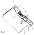
- FIG. 1 is a perspective view of a housing 1 of a back Device shown.
- a device system according to the Invention has at least one arranged in the housing 1 Device up. This is e.g. an evaluation or switching device a level, pressure, flow or Temperature measuring. The device is mechanical in one place to attach and connect electrically.
- Fig. 2 is a carrier 3 in perspective with view a front shown, this mechanical Attachment serves.
- the carrier 3 has on a rear side a non-visible, as hidden in Fig. 2 Snap holder 5 on, with the carrier 3 on a Rail, e.g. a DIN rail screwed to a wall, is latched.
- the carrier 3 can also be on a wall be screwed directly.
- a cable holder. 7 provided in which a not shown in Fig. 2 cable, e.g. a multi-core ribbon cable, insert is.
- the housing 1 is detachably mounted on the carrier 3.
- a recess 11 is provided, which is substantially a matching to the shape of the front of the carrier 3 Has shape.
- One end of the carrier 3 has a rounded shoulder 13 on which the housing 1 is pivotable during assembly is put on.
- the housing 1 has an end in the recess 11 a Undercut 15, which surrounds the shoulder 13. By turning the housing 1 by one of the shoulder thirteenth formed axis, the housing 1 on the support. 3 placed. At the rear of the 15 opposite lying side of the housing 1 is a projection 17 with a bore 19 formed through which one in the Figures unrepresented fastening screw in the Carrier 3 is screwed.
- the housing 1 also has on its underside Cutting contacts 21 which protrude into the recess 11 and in the assembled state electrical contact with wires of a Make cable inserted in the cable holder 7.
- the carrier 3 is on each side wall with side by side arranged first grooves 23 provided perpendicular to Run front surface of the carrier 3 and the front surface of the Support 3 and the associated side wall are open.
- the interiors of the Grooves 23 have a cross-section in T-shape, and two each other adjacent grooves 23 are separated from each other by a likewise T-shaped bridge 25 separated.
- the housing 1 In the housing 1 are the same shape equal to the grooves 23 second grooves 27 arranged. These are in two each other opposite side walls 28 of the housing 1, which the Limit recess 11.
- the interiors of the grooves 27 also have one Cross section in T-shape, and two adjacent grooves 27 are separated from each other by a web 29 in T-shape.
- Each of these T-shapes has a T-bar and a T-leg, which has a foot area.
- each groove 23 of the carrier 3 is a Groove 27 of the housing 1 assigned spatially. Two grooves 23 and 27 of a pair of grooves each border with the associated foot surface together.
- Fig. 4 shows such a Kodierstatt 31.
- This includes a rod 33 with a longitudinal axis and one at one end of the rod 33 integrally formed extension 35, located in a extends at right angles to the longitudinal axis.
- Each coding pin 31 may either be in one of the first grooves Groove 23 or in a groove 27 belonging to the second grooves be fixed.
- Fig. 3 are illustrative three Kodierstatte 31st positioned in three grooves 27 of the housing 1.
- the coding pins 31 are inserted in the grooves 23 and 27, respectively, with the end of the rod 33 facing away from the extension 35.
- the extension 35 extends at right angles to the rod 33 through the T-foot of the corresponding groove 27 into the T-leg of the opposite groove 23 of the carrier. 3
- the respective grooves 23 and 27 facing each other in FIG. 3 form a pair of grooves.
- the dimensions are chosen so that the cavity, which is formed by the interiors of the grooves 23, 27 of a pair of grooves, is suitable for receiving exactly one coding pin 31.
- there is insufficient space in the cavity because the extension 35 of a coding pin 31 arranged in a first groove 23 or 27 extends into the interior of the second groove 27 or 23 of the groove pair adjoining the first groove 23 or 27.
- Each coding pin 31 has at the remote from the extension 35 End at least one protruding clamping device, in Embodiment of FIG. 3, this has the form of a protruding clamping lug 37. This is the introduction of a Coding pin 31 clamped in the groove 23 and 27 respectively.
- the coding pins 31 are detachable in the grooves 23, 27 fixed. It can also be a spring-loaded knob or another type of clamping device for releasable fixation be used. With each coding pin 31, which in one the grooves 23 and 27 is fixed, its extension 35 protrudes out of the groove 23 and 27 out. By hand or by means of a Screwdriver can reach under the extension 35, to remove the coding pin 31.
- housing 1 and support 3 can from the Manufacturer e.g. all grooves 23 or all grooves 27 with Coded pins 31 equipped.
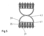
- assembly aid can be used.
- This includes a bar 39, on which the coding pins 31 side by side are attached via narrow bridges 41.
- the extension 35 having ends of the coding pins 31 are the strip 39th facing.
- the number of coding pins 31 on a strip 39th is equal to the number in the housing 1 or on the carrier 3 juxtaposed grooves 23 and 27th
- the distance between the coding pins 31 is the same Distance between the juxtaposed grooves 23rd or 27 selected.
- To the bar 39 is a handle 43rd formed.
- the mounting aid is taken on the handle 43, and All coding pins 31 attached thereto become simultaneously inserted into the grooves 23 and 27, respectively. Then be by bending the handle 43 through the bridges 41 formed breaking points separated and bar 39 and Handle 43 removed.
- the coding pins 31 are mentioned in the Assembly of housing 1 and carrier 3 in the housing 1, ie in the grooves 27, arranged.
- the user can then self a coding optimally adapted to his needs make by individual coding pins 31 from the grooves 27th removed and in the associated grooves 23 of the Carrier 3 are used.
- too Markers e.g. Color markings, letters or Numbers to identify the two grooves 23 and 27 of a Nutenproes provided.
- n (n greater than or equal to 2) pairs of grooves are provided, are also n coding pins 31 available; then that is Number of possible different codings 2n. at Twelve pairs of grooves are already 4096 different Encodings.
- the number of possible encodings can be even further can be increased by increasing the number of grooves becomes.
- a partition on one or provided on both sides with further grooves e.g. a carrier with a complementary thereto formed recess, at the Inner walls, the associated grooves are arranged.
- two carriers could be used in conjunction with one be provided such a housing.
- this housing on at least two carriers at the same time mountable.
- the user can choose one optimized for his applications Defining coding scheme. He can e.g. some of the Use coding pins 31 to mark the device type, and use more to certain locations for specify multiple devices of the same type.
- the manufacturer-side arrangement of the coding pins 31 in Housing 1 has the advantage that the user in the Installing a replacement device to make a conscious Action is forced. He must namely the coding pins 31st according to the existing on the carrier 3 coding from the Remove housing 1 of the replacement device.
Landscapes
- Casings For Electric Apparatus (AREA)
- Details Of Measuring And Other Instruments (AREA)
- Accommodation For Nursing Or Treatment Tables (AREA)
Claims (16)
- Système d'appareil comprenant au moins un appareil disposé dans un boítier (1), notamment un appareil d'évaluation ou un appareil de commutation pour un capteur de mesure disposé de façon éloignée dudit appareil de commutation,
caractérisé en ce que,le système d'appareil comprend en outre, au moins un support (3) prévu pour le boítier (1),le support (3) étant directement vissé à une paroi ou encliqueté sur un profilé chapeau vissé à une paroi et le boítier (1) pouvant être monté de façon mobile sur au moins un support (3), etqu'on a prévu des moyens (23,25, 27, 31) pour coder une affectation du boítier (1) au support (3) disposés sur le boítier (1) et sur le support (3) pour empêcher un équipement erroné du support (3) par un autre appareil, notamment un type d'appareil comparable au type de l'appareil (1),les moyens (23, 25, 27, 31) pour le codage de l'affectation du boítier (1) au support (3) étant constitués de cavités (23, 25, 27, 29) formées dans le support (3) et le boítier (1) ainsi de tiges de codage (31) disposées dans les cavités. - Système d'appareil selon la revendication 1, dans lequel système d'appareil on garde la possibilité de modifier un codage défini du système d'appareil par une disposition momentanée des tiges de codage (31) sur le boítier (1) et/ou sur le support (3).
- Système d'appareil selon la revendication 1 ou 2, dans lequel le système d'appareil on a fixé de façon mobiles à l'intérieur des espaces creux les tiges de codage (31) fixées au support (3) et les tiges de codage (31) fixées au boítier (1).
- Système selon une des revendications précédentes, dans lequel système d'appareil on a disposé dans le support, une première rainure (23) et dans le boítier, une deuxième rainure (27) pour la réception des tiges de codage (31) ; une rainure appartenant aux premières rainures (23) formant à chaque fois une paire de rainures avec la rainure appartenant aux deuxièmes rainures (27) dans l'état de montage, en formant à chaque fois un espace creux fermé.
- Système d'appareil selon la revendication précédente, dans lequel système d'appareil, on a disposé à chaque fois une tige de codage dans au moins deux espaces creux formés par une paire de rainures.
- Système d'appareil selon la revendication 4 ou 5, dans lequel système d'appareil chacune des tiges de codage utilisées est fixée exactement dans une des deux rainures de chaque paire de rainures.
- Système d'appareil selon une des revendications précédentes, dans lequel système d'appareil, le support (3) est encliqueté sur le profilé chapeau vissé, notamment à une paroi d'une armoire.
- Système d'appareil selon la revendication 7, dans lequel système d'appareil, le codage peut être aussi modifié par un support (3) encliqueté sur un profilé chapeau.
- Système d'appareil selon la revendication 7 ou 9, dans lequel système d'appareil on a crée un contact électrique du boítier (1) avec un câble introduit dans un support de câble (7) du support (3) au moyen de contact (21) disposés sur un côté inférieur du boítier.
- Système d'appareil selon une des revendications précédentes, dans lequel système d'appareil, le support (3) est vissé à une paroi, notamment la paroi d'une armoire.
- Système d'appareil selon la revendication 10, dans lequel système d'appareil, on peut également modifier le codage par un support (3) vissé dans la paroi.
- Système d'appareil selon une des revendications précédentes, dans lequel système d'appareil, on peut définir la codification également par un utilisateur avant la construction.
- Système d'appareil selon une des revendications précédentes, dans lequel système d'appareil, un schéma de codage du codage marque un type d'appareil de l'appareil.
- Système d'appareil selon une des revendications précédentes, dans lequel système d'appareil, un schéma de codage indique le codage d'un lieu d'utilisation prévu pour l'appareil.
- Système d'appareil selon une des revendications précédentes, dans lequel système d'appareil, l'appareil est un appareil d'évaluation pour un capteur de mesure disposé de manière éloignée dudit appareil d'évaluation.
- Système d'appareil selon une des revendications précédentes, dans lequel système d'appareil, l'appareil est un appareil de commutation pour un capteur de mesure disposé de manière éloignée dudit appareil de commutation.
Priority Applications (1)
| Application Number | Priority Date | Filing Date | Title |
|---|---|---|---|
| EP99108483A EP0959533B9 (fr) | 1998-05-19 | 1999-04-30 | Système appareillage |
Applications Claiming Priority (3)
| Application Number | Priority Date | Filing Date | Title |
|---|---|---|---|
| EP98109069 | 1998-05-19 | ||
| EP98109069 | 1998-05-19 | ||
| EP99108483A EP0959533B9 (fr) | 1998-05-19 | 1999-04-30 | Système appareillage |
Publications (3)
| Publication Number | Publication Date |
|---|---|
| EP0959533A1 EP0959533A1 (fr) | 1999-11-24 |
| EP0959533B1 EP0959533B1 (fr) | 2005-09-07 |
| EP0959533B9 true EP0959533B9 (fr) | 2005-11-09 |
Family
ID=8231957
Family Applications (1)
| Application Number | Title | Priority Date | Filing Date |
|---|---|---|---|
| EP99108483A Expired - Lifetime EP0959533B9 (fr) | 1998-05-19 | 1999-04-30 | Système appareillage |
Country Status (6)
| Country | Link |
|---|---|
| US (1) | US6142592A (fr) |
| EP (1) | EP0959533B9 (fr) |
| JP (1) | JP3034866B2 (fr) |
| CN (1) | CN1100360C (fr) |
| CA (1) | CA2271550C (fr) |
| DE (1) | DE59912515D1 (fr) |
Families Citing this family (16)
| Publication number | Priority date | Publication date | Assignee | Title |
|---|---|---|---|---|
| DE19964150A1 (de) * | 1999-01-25 | 2000-09-07 | Weidmueller Interface | Kodiervorrichtung zur Kodierung eines elektrischen Gerätes |
| US7319386B2 (en) | 2004-08-02 | 2008-01-15 | Hill-Rom Services, Inc. | Configurable system for alerting caregivers |
| DE102011055920B3 (de) * | 2011-12-01 | 2013-05-29 | Pilz Gmbh & Co. Kg | Separates Zubehörelement für eine Steuerungsvorrichtung |
| US9314159B2 (en) | 2012-09-24 | 2016-04-19 | Physio-Control, Inc. | Patient monitoring device with remote alert |
| PL2991170T3 (pl) | 2014-08-27 | 2018-03-30 | Selectron Systems Ag | Układ części modułowych i regulowanych środków kodujących |
| DE202015104355U1 (de) * | 2015-08-18 | 2016-11-23 | Wago Verwaltungsgesellschaft Mbh | Kodiererzeugnis |
| DE102016118870A1 (de) * | 2016-10-05 | 2018-04-05 | Lumberg Connect Gmbh | Steckverbinder mit entfernbaren Kodierstiften |
| EP3331334B1 (fr) * | 2016-11-30 | 2021-05-19 | TE Connectivity Germany GmbH | Agencement de module avec mécanisme de réarmement |
| US11123014B2 (en) | 2017-03-21 | 2021-09-21 | Stryker Corporation | Systems and methods for ambient energy powered physiological parameter monitoring |
| US11229568B2 (en) | 2018-09-30 | 2022-01-25 | Hill-Rom Services, Inc. | Mattress support for adding hospital bed functionality to an in-home bed |
| US11357682B2 (en) | 2018-09-30 | 2022-06-14 | Hill-Rom Services, Inc. | Structures for causing movement of elements of a bed |
| US11367535B2 (en) | 2018-09-30 | 2022-06-21 | Hill-Rom Services, Inc. | Patient care system for a home environment |
| US11400001B2 (en) | 2018-10-01 | 2022-08-02 | Hill-Rom Services, Inc. | Method and apparatus for upgrading a bed to include moveable components |
| US11241347B2 (en) | 2018-10-01 | 2022-02-08 | Hill-Rom Services, Inc. | Mattress support for adding hospital bed modular control system for upgrading a bed to include movable components |
| US10959534B2 (en) | 2019-02-28 | 2021-03-30 | Hill-Rom Services, Inc. | Oblique hinged panels and bladder apparatus for sleep disorders |
| DE202022106490U1 (de) | 2022-11-21 | 2024-02-27 | WAGO Verwaltungsgesellschaft mit beschränkter Haftung | Kodierbauteil und Kodierelement sowie Set aus Steckverbinder und Kodierbauteil |
Family Cites Families (12)
| Publication number | Priority date | Publication date | Assignee | Title |
|---|---|---|---|---|
| GB1243367A (en) * | 1968-10-16 | 1971-08-18 | Belling & Lee Ltd | Improvements in or relating to electrical connectors |
| DE2455409C3 (de) * | 1974-11-22 | 1981-11-19 | Siemens AG, 1000 Berlin und 8000 München | Codiervorrichtung für Mehrfach-Steckvorrichtungen |
| CH586962A5 (en) * | 1975-08-25 | 1977-04-15 | Siemens Ag Albis | Coding assembly to prevent incorrect block connection - uses identical keys locating in slots in block edges |
| DE2807017C3 (de) * | 1978-02-18 | 1982-01-14 | F. Wieland, Elektrische Industrie GmbH, 8600 Bamberg | Mehrpolige kodierbare Steckverbindung |
| DE3014804C2 (de) * | 1980-04-17 | 1982-06-16 | C.A. Weidmüller KG, 4930 Detmold | Steckverbinder |
| US4533203A (en) * | 1983-12-07 | 1985-08-06 | Amp Incorporated | Connector for printed circuit boards |
| DE3673391D1 (de) * | 1986-03-05 | 1990-09-13 | Weidmueller C A Gmbh Co | Mehrpoliger steckverbinder. |
| EP0235339B1 (fr) * | 1986-03-05 | 1990-09-05 | C.A. Weidmüller GmbH & Co. | Connecteur électrique multipolaire |
| FR2642231B3 (fr) * | 1989-01-25 | 1991-04-05 | Francelco Sa | Perfectionnements aux connecteurs electriques |
| DE3933703A1 (de) * | 1989-10-09 | 1991-04-18 | Pepperl & Fuchs | Stromschiene zur elektrischer kontaktierung von geraeten |
| GB9101716D0 (en) * | 1991-01-25 | 1991-03-06 | Marshall C & C Ltd | Trunking and busbars assembly |
| DE9208701U1 (fr) * | 1992-06-29 | 1992-12-17 | Siemens Ag, 8000 Muenchen, De |
-
1999
- 1999-04-28 US US09/301,236 patent/US6142592A/en not_active Expired - Fee Related
- 1999-04-30 DE DE59912515T patent/DE59912515D1/de not_active Expired - Fee Related
- 1999-04-30 EP EP99108483A patent/EP0959533B9/fr not_active Expired - Lifetime
- 1999-05-10 CA CA002271550A patent/CA2271550C/fr not_active Expired - Fee Related
- 1999-05-19 JP JP11139120A patent/JP3034866B2/ja not_active Expired - Fee Related
- 1999-05-19 CN CN99106759.2A patent/CN1100360C/zh not_active Expired - Fee Related
Also Published As
| Publication number | Publication date |
|---|---|
| EP0959533A1 (fr) | 1999-11-24 |
| US6142592A (en) | 2000-11-07 |
| CA2271550C (fr) | 2002-06-18 |
| DE59912515D1 (de) | 2005-10-13 |
| JPH11352267A (ja) | 1999-12-24 |
| EP0959533B1 (fr) | 2005-09-07 |
| CN1238574A (zh) | 1999-12-15 |
| CN1100360C (zh) | 2003-01-29 |
| JP3034866B2 (ja) | 2000-04-17 |
| CA2271550A1 (fr) | 1999-11-19 |
Similar Documents
| Publication | Publication Date | Title |
|---|---|---|
| EP0959533B9 (fr) | Système appareillage | |
| EP1189307B1 (fr) | Barette à bornes électrique | |
| EP0798819B1 (fr) | Dispositif pour la fixation détachable d'un ou de plusieurs appareils à un ou plusieurs endroits et pour leur connexion électrique | |
| EP1251590B1 (fr) | Borne électrique | |
| EP2351154B1 (fr) | Agencement de bornes en série avec raccordements transversaux et connecteurs d'essai | |
| EP0658463A2 (fr) | Dispositif de contrôle pour soupape | |
| DE19650989A1 (de) | Reihenklemme mit seitlichen Brückungskontakten | |
| EP2491622B1 (fr) | Système destiné à relier des conducteurs électriques ayant des potentiels différents, ainsi qu'adaptateur enfichable pour le système | |
| DE102016124172A1 (de) | Steckverbinder zur kraftlosen Kontaktierung auf einer Leiterkarte | |
| DE3409211A1 (de) | Trageinrichtung zur aufnahme von installationsgeraeten | |
| DE4320327C1 (de) | Aktuatoren oder Sensoren zum Anschluß an eine Busleitung | |
| DE2718442C3 (de) | Baugruppe, enthaltend eine mit einer gedruckten Schaltung versehene Grundplatte und eine Haltevorrichtung zur Halterung und Justierung mehrerer nebeneinander liegender elektronischer Bauelemente | |
| DE2912208C2 (de) | Elektrisches Gerät, insbesondere Installationsgerät | |
| EP0019141A1 (fr) | Interrupteur à cames | |
| DE10227422A1 (de) | Datenumwandler | |
| DE2355509C2 (de) | Montageeinheit für Elektro-Installationszwecke | |
| DE19514842B4 (de) | Prozeßstecker | |
| EP0776077A2 (fr) | Dispositif pour le montage d'accessoires sur des rails DIN | |
| WO1994024728A1 (fr) | Connecteur a encliqueter pour conducteurs electriques | |
| DE3641153C2 (fr) | ||
| DE102005047045B3 (de) | Anschlussadapter | |
| DE4305844C2 (de) | Steckverbinder | |
| DE4414148A1 (de) | Stromschiene mit Querbrückung für Schaltanlagen-Reihenklemmen | |
| DE2723725C3 (de) | Elektrische Mehrfachkupplung | |
| DE4037153C2 (de) | Schalthebel eines Lenkstockschalters für Fahrzeuge |
Legal Events
| Date | Code | Title | Description |
|---|---|---|---|
| PUAI | Public reference made under article 153(3) epc to a published international application that has entered the european phase |
Free format text: ORIGINAL CODE: 0009012 |
|
| AK | Designated contracting states |
Kind code of ref document: A1 Designated state(s): DE FR GB IT |
|
| AX | Request for extension of the european patent |
Free format text: AL;LT;LV;MK;RO;SI |
|
| 17P | Request for examination filed |
Effective date: 20000406 |
|
| AKX | Designation fees paid |
Free format text: DE FR GB IT |
|
| 17Q | First examination report despatched |
Effective date: 20010315 |
|
| RAP1 | Party data changed (applicant data changed or rights of an application transferred) |
Owner name: ENDRESS + HAUSER GMBH + CO.KG. |
|
| GRAP | Despatch of communication of intention to grant a patent |
Free format text: ORIGINAL CODE: EPIDOSNIGR1 |
|
| GRAS | Grant fee paid |
Free format text: ORIGINAL CODE: EPIDOSNIGR3 |
|
| GRAA | (expected) grant |
Free format text: ORIGINAL CODE: 0009210 |
|
| AK | Designated contracting states |
Kind code of ref document: B1 Designated state(s): DE FR GB IT |
|
| REG | Reference to a national code |
Ref country code: GB Ref legal event code: FG4D Free format text: NOT ENGLISH |
|
| GBT | Gb: translation of ep patent filed (gb section 77(6)(a)/1977) |
Effective date: 20050907 |
|
| REF | Corresponds to: |
Ref document number: 59912515 Country of ref document: DE Date of ref document: 20051013 Kind code of ref document: P |
|
| ET | Fr: translation filed | ||
| PLBE | No opposition filed within time limit |
Free format text: ORIGINAL CODE: 0009261 |
|
| STAA | Information on the status of an ep patent application or granted ep patent |
Free format text: STATUS: NO OPPOSITION FILED WITHIN TIME LIMIT |
|
| 26N | No opposition filed |
Effective date: 20060608 |
|
| PGFP | Annual fee paid to national office [announced via postgrant information from national office to epo] |
Ref country code: DE Payment date: 20080418 Year of fee payment: 10 |
|
| PGFP | Annual fee paid to national office [announced via postgrant information from national office to epo] |
Ref country code: IT Payment date: 20080424 Year of fee payment: 10 |
|
| PGFP | Annual fee paid to national office [announced via postgrant information from national office to epo] |
Ref country code: FR Payment date: 20080412 Year of fee payment: 10 |
|
| PGFP | Annual fee paid to national office [announced via postgrant information from national office to epo] |
Ref country code: GB Payment date: 20080421 Year of fee payment: 10 |
|
| GBPC | Gb: european patent ceased through non-payment of renewal fee |
Effective date: 20090430 |
|
| REG | Reference to a national code |
Ref country code: FR Ref legal event code: ST Effective date: 20091231 |
|
| PG25 | Lapsed in a contracting state [announced via postgrant information from national office to epo] |
Ref country code: DE Free format text: LAPSE BECAUSE OF NON-PAYMENT OF DUE FEES Effective date: 20091103 |
|
| PG25 | Lapsed in a contracting state [announced via postgrant information from national office to epo] |
Ref country code: GB Free format text: LAPSE BECAUSE OF NON-PAYMENT OF DUE FEES Effective date: 20090430 Ref country code: FR Free format text: LAPSE BECAUSE OF NON-PAYMENT OF DUE FEES Effective date: 20091222 |
|
| PG25 | Lapsed in a contracting state [announced via postgrant information from national office to epo] |
Ref country code: IT Free format text: LAPSE BECAUSE OF NON-PAYMENT OF DUE FEES Effective date: 20090430 |