EP0959446A2 - Writable vulcanisable labels and device and method to write on and to apply them - Google Patents
Writable vulcanisable labels and device and method to write on and to apply them Download PDFInfo
- Publication number
- EP0959446A2 EP0959446A2 EP99109810A EP99109810A EP0959446A2 EP 0959446 A2 EP0959446 A2 EP 0959446A2 EP 99109810 A EP99109810 A EP 99109810A EP 99109810 A EP99109810 A EP 99109810A EP 0959446 A2 EP0959446 A2 EP 0959446A2
- Authority
- EP
- European Patent Office
- Prior art keywords
- engraving
- laser
- component
- tire
- vulcanette
- Prior art date
- Legal status (The legal status is an assumption and is not a legal conclusion. Google has not performed a legal analysis and makes no representation as to the accuracy of the status listed.)
- Granted
Links
Images


Classifications
-
- G—PHYSICS
- G09—EDUCATION; CRYPTOGRAPHY; DISPLAY; ADVERTISING; SEALS
- G09F—DISPLAYING; ADVERTISING; SIGNS; LABELS OR NAME-PLATES; SEALS
- G09F3/00—Labels, tag tickets, or similar identification or indication means; Seals; Postage or like stamps
- G09F3/04—Labels, tag tickets, or similar identification or indication means; Seals; Postage or like stamps to be fastened or secured by the material of the label itself, e.g. by thermo-adhesion
-
- G—PHYSICS
- G09—EDUCATION; CRYPTOGRAPHY; DISPLAY; ADVERTISING; SEALS
- G09F—DISPLAYING; ADVERTISING; SIGNS; LABELS OR NAME-PLATES; SEALS
- G09F3/00—Labels, tag tickets, or similar identification or indication means; Seals; Postage or like stamps
-
- B—PERFORMING OPERATIONS; TRANSPORTING
- B29—WORKING OF PLASTICS; WORKING OF SUBSTANCES IN A PLASTIC STATE IN GENERAL
- B29D—PRODUCING PARTICULAR ARTICLES FROM PLASTICS OR FROM SUBSTANCES IN A PLASTIC STATE
- B29D30/00—Producing pneumatic or solid tyres or parts thereof
- B29D30/06—Pneumatic tyres or parts thereof (e.g. produced by casting, moulding, compression moulding, injection moulding, centrifugal casting)
- B29D30/72—Side-walls
- B29D2030/728—Decorating or marking the sidewalls after tyre vulcanization
Definitions
- the invention relates to a device and a Process for the production of vulcanizable labels, so-called vulcanettes.
- the invention also relates to the Vulcanettes and those with such Vulcanettes Objects.
- Tires or other subject to a vulcanization process Components are used to carry out the vulcanization process placed in an appropriate form and in this Form a period of higher pressure and higher temperature exposed.
- the component is attached to the mold wall pressed, which is molded from the component. This can markings, labels and other structures the mold wall. In practice, this becomes used, for example in tire manufacture, tire size and tire type as well as manufacturer and other information to be shown on the tire in raised script. This way is usually not feasible, however, if the on the Tire signs, symbols or representations to be noted change frequently or only occasionally.
- the labeled one Carrier also known as a vulcanette can in this process step without additional Effort regarding the handling of the component on the Component are attached.
- the Vulcanettes are in the vulcanization process that the tire is subjected to is vulcanized on the tire, for example on its side wall and are therefore permanent and captive on the Tires kept.
- the laser engraving on the vulcanette stands in good optical contrast to the preferred otherwise smooth or at least uniform trained surface of the vulcanette and is therefore good readable. Older engravings on the tire can be covered. When laser marking the vulcanettes always a suitable labeling surface provided.
- the volcanoes can run from a longer band be separated. It is both possible separate sections as well as from the tape rectangular volcanoes with rounded corners or separate with other outer contours.
- a laser unit is used, which is also used for Engraving of the carrier is used. For example, it can Switching the power and / or changing the feed speed of the laser beam can be reached. While with laser engraving only surface areas of the carrier roughened and removed in the focal spot of the laser beam deeper penetration is created during the cut.
- the engraving of the vulcanettes can be so deep that the engraving breaks through the base material.
- the engraving is preferably only superficial. Nevertheless, a good and lasting readability of the Vulcanette even after vulcanization towards it characteristic component reached.
- the Vulcanette will thereby with their component side to the component, and with an appropriate vulcanizing form on the outside with walls smooth in this area. Yet the engraving produced smooths out during printing and Exposure to heat not too far, so legibility remains ensured. This applies to both solid colors Vulcanettes as well as multicolored for Vulcanettes are trained, for example by using several different Have layers of material.
- E.g. can be a black Basic material from 5 to 8 tenths of a millimeter with one yellow, to be partially or completely applied to the engraving Cover material from 2 to 3 tenths of a millimeter as a carrier material Find application.
- a vulcanizable one To use backing material on the Engraving side, e.g. an aluminum foil or vapor deposition who carries out the laser engraving in areas and selectively is removed. Other surface coatings are possible.
- Vulcanettes at least on the component side with vulcanized Material can be provided before the vulcanization process be attached to the component. Because they are not yet vulcanized, they adhere relatively well the place where they are attached so that the component is safe to use and inserted in a mold, for example can be made without losing the Vulkanette.
- a major advantage of the laser-engraved vulcanettes is that they can be made individually are.
- a corresponding labeling device is used for this, which has a control unit, the engraving unit controls according to received data.
- the Data can be entered manually, from a Interface or other means of data collection come from.
- the labeling device is therefore in able to make different volcanettes in a row. These will be especially when the laser unit is operable in two-power operation, both with the provided information engraved, as well as cut out or trimmed.
- the labeling device preferably with a tape feed provided that a carrier material tape gradually on the Engraving unit passes.
- a tire 1 is illustrated in FIG a retreading process with a new profile 2 has been provided.
- the tire 1 has side walls 3, 4 on, which are usually labeled 5.
- the side wall 3 is provided with vulcanettes 7, 8, through a 1mm thick, on the side wall 3 of the Tire 1 vulcanized rubber sheet are formed.
- the Vulcanettes 7, 8 have a superficial engraving 9 that e.g. font, characters, logos, technical information, Reproduces brand names or the like.
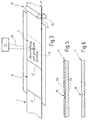
- A is used for the production Labeling device 10 according to Figures 3 and 4.
- Die Labeling device 10 contains a base frame 11, by which a laser unit 12 is carried.
- the laser unit 12 contains a laser 13, one of which emits light upstream chute 14 and a scanner 15, with which a focused laser beam within an in Figure 4 illustrated with thick solid lines Area 16 is movable.
- To accommodate a tape 17 from a suitable carrier material serves a table 18 which is carried by the base frame 11.
- the tape 17 will only symbolically by two in FIG Rollers 21, 22 illustrate feed device 23 moved gradually over the table 18.
- the band 17 can be a flat band with two each other opposite plan pages. Can if necessary however also fixed structures 19, such as logos, lines, Tables or the like can be pre-embossed, as in FIG. 7 is illustrated. This has the advantage that a Contrast to the rather flat laser engraving can be produced.
- the pre-embossed areas 19 can be raised or indented be.
- the engraving area 24, which is from the movement area 16 of the scanner 15 is determined in the field of view of a camera 25 arranged, one in Figure 4 with extended Lines shown image capture area 27.
- Both the engraving unit 12 and the camera 26 are to a control unit which is only indicated schematically 28 connected, for example by a microcomputer or a computer is formed.
- a display unit 29 for example as a flat screen 30 is formed, and an input unit 31, for example a keyboard.
- the control unit 28 an interface 32 for data communication with a external computing system or with another system exhibit.
- the control unit 28 is programmed and trained that the flat panel 30 or other Display device at the same time that of the camera 26 recorded picture and the inscription or other engraving brings to the display that applied to the tape 17 shall be. This is done on the screen 30 as the image background first volume 17 is shown. On the Screen 30 also shows a window 33, which contains the engraving 9 to be applied. The content of the Window 33 can by inputs on the keyboard 31 or changed or produced via the interface 32 become.
- the window 33 is somewhat transparent trained, i.e. the image captured by camera 26 is used as the background for window 33.
- the Image can be modified or falsified for identification be, for example, in the brightness values, contrast values or Color values are changed more or less.
- the field 33 can carry a frame.
- the field 33 is optional on the screen 30 slidable; so that it is placed at any desired location can be. This is by arrows x for horizontal shift, y for vertical displacement and r for Rotation or rotation illustrated. Besides that Field 33 scalable, as indicated by arrows s, y and s, x is. It can also be enlarged proportionally or scalable like the lower left arrow sp illustrated. If necessary, the display field 33 in Subfields are split. In addition, more communication fields on the screen 30 are displayed, which then blend the existing image.
- the control unit 28 is designed or programmed in such a way that that when the engraving process is triggered, that of the laser unit 12 produced engraving on pretty much that Places the belt 17 is generated, at which they were previously on the screen 30 by positioning the Field 33 have been displayed.
- the picture of band 17 is a live picture.
- the engraving process can therefore be timed be observed on the monitor. Reenactments regarding the engraving depth or quality are therefore manual easily possible.
- FIGS. 5 and 6 Various embodiments are shown in FIGS. 5 and 6 illustrated by ribbons 17 from which volcanettes are producible.
- the band 17 according to FIG. 5 has two layers built up. With a total thickness of about 1mm it has, for example, a colored base layer 17a made of non-vulcanized material, e.g. rubber. On this material is a thin layer of 2 to 3 tenths Millimeters 17b arranged in the present case also consists of unvulcanized rubber. She can For example, be black in order to create a color contrast to the colored one To create carrier material 17a. Alternatively, the Layer 17b also much thinner and / or from one other material, such as a metal be.
- this Depression 36 is largely the material of layer 17b or completely removed so that the underlying one Layer 17a becomes visible.
- the top layer is 17b
- black and the underlying layer 17a, for example. yellow, is the label symbolically shown in Figure 3 readable in yellow on black.
- Carrier can be used, which consists of a single Material of the same color exists.
- the engraving will again through depressions of 1 to 3 tenths of a millimeter deep formed.
- the stroke width can also just a few tenths of a millimeter, a millimeter or be more.
- the labeling device according to FIG. 3 or 4 is entered 31 on the input unit (keyboard) or via the data link 32 with information about the engraving to be applied.
- the laser unit 12 brings, as indicated in Figure 3, the desired graphic information on the tape 17 by the Laser beam 15 engraves the surface of the tape 17.
- the laser beam separates each time an engraving is finished 35 from the band 17 individual volcanic chains 7, 8, as by thick solid dividing lines 41, 42 in Figure 3 is illustrated.
- the volcanoes 7, 8 thus produced are then on the Tire 1 or attached to other components. you carry thereby adhering to the surface without falling off.
- the tire 1 is now shown schematically in FIG illustrated vulcanizing mold 44 inserted, one Has cavity 45 for receiving the tire 1.
- the Vulcanizing mold 44 instructs on its mold halves 46, 47 the inward side a smooth or at least partially smooth surface.
- the tire 1 is now inserted into the vulcanizing mold 44 in such a way that the Vulcanettes 7, 8 come to rest in areas where the inner wall of the vulcanizing mold 44 is smooth, i.e. Not is provided with profiles.
- the engraving on the side facing outwards the Vulcanette is permanently visible. Through the vulcanization process the engraving is hardened and remains over the Tire life 1 readable.
- the engraving 9 also in existing patterns or knockouts be fitted.
- the engraving with field 33 brought into the desired size, shape and position. Then the engraving process is triggered.
- volcanoes can loosely engrave objects in this way can also be coated directly.
- Vulkanetten 8 which are made of vulcanized material exist and can be labeled with laser engraving are.
- the vulcanettes are affected by pressure and heat is pressed onto the component to be labeled and harden or vulcanize, or on this.
Landscapes
- Physics & Mathematics (AREA)
- General Physics & Mathematics (AREA)
- Engineering & Computer Science (AREA)
- Theoretical Computer Science (AREA)
- Moulds For Moulding Plastics Or The Like (AREA)
- Heating, Cooling, Or Curing Plastics Or The Like In General (AREA)
- Laser Beam Processing (AREA)
- Manufacture Of Macromolecular Shaped Articles (AREA)
Abstract
Description
Die Erfindung betrifft eine Vorrichtung und ein Verfahren zum Herstellen von vulkanisierbaren Etiketten, sogenannten Vulkanetten. Außerdem betrifft die Erfindung die Vulkanetten und mit solchen Vulkanetten versehene Gegenstände. The invention relates to a device and a Process for the production of vulcanizable labels, so-called vulcanettes. The invention also relates to the Vulcanettes and those with such Vulcanettes Objects.
Technische Bauteile wie Reifen, Metall-Gummi-Verbundteile, Maschinenelemente, Silentbuchsen und ähnliche Gegenstände sind häufig mit Markierungen, Beschriftungen, graphischen Symbolen oder Logos zu versehen, die dauerhaft und gut lesbar an dem Bauteil angebracht werden sollen. Bspw. kann es von Interesse sein Schargennummern, Hersteller, Herstellzeitpunkt und ähnliche Sachinformation an dem betreffenden Bauteil anzubringen. Bei runderneuerten Reifen wird häufig gewünscht, die erneuerten Reifen zu beschriften, um solche Informationen nach dem Runderneuern gut lesbar an dem Reifen verfügbar zu halten.Technical components such as tires, metal-rubber composite parts, Machine elements, silent bushings and the like Objects are often marked, labeled, to provide graphic symbols or logos that are permanent and be attached to the component in a legible manner should. E.g. it may be of interest Manufacturer, time of manufacture and similar factual information to be attached to the component in question. With retreaded Tires are often desired, the renewed ones To label such information after the tire Keep retreads easily readable on the tire.
Reifen oder sonstige einem Vulkanisierprozess unterworfene Bauteile werden zur Durchführung des Vulkanisiervorgangs in eine entsprechende Form gelegt und in dieser Form eine gewisse Zeit höherem Druck und höherer Temperatur ausgesetzt. Das Bauteil wird dabei an die Formwandung angepresst, die sich dabei an dem Bauteil abformt. Dies können Markierungen, Beschriftungen und sonstige Strukturen der Formwand sein. Dies wird in der Praxis dazu verwendet, bspw. bei der Reifenherstellung, Reifengröße und Reifentyp sowie Hersteller und sonstige Informationen an dem Reifen in erhabener Schrift abzubilden. Dieser Weg ist jedoch dann meist nicht gangbar, wenn die an dem Reifen zu vermerkenden Zeichen, Symbole oder Darstellungen häufig oder auch nur gelegentlich wechseln.Tires or other subject to a vulcanization process Components are used to carry out the vulcanization process placed in an appropriate form and in this Form a period of higher pressure and higher temperature exposed. The component is attached to the mold wall pressed, which is molded from the component. This can markings, labels and other structures the mold wall. In practice, this becomes used, for example in tire manufacture, tire size and tire type as well as manufacturer and other information to be shown on the tire in raised script. This way is usually not feasible, however, if the on the Tire signs, symbols or representations to be noted change frequently or only occasionally.
Technische Bauteile unterliegen häufig Einwirkungen und Angriffen, die Spuren auf der Oberfläche hinterlassen und aufgebrachte Markierungen, bspw. Farbmarkierungen beschädigen, entfernen oder zumindest überdecken. Dies können Ölablagerungen, Verschmutzungen (bei Reifen), Abrasionswirkung (ebenfalls bei Reifen) oder Abnutzungserscheinungen sein. Wird an einem Reifen bspw. die Anzahl der Runderneuerungen vermerkt, muss dieser Vermerk auch gegen Ende der Lebensdauer der jeweiligen Runderneuerung noch gut lesbar sein, um den Reifen rechtzeitig aus dem Zyklus nehmen zu können. Bei Flugzeugreifen die sehr häufig (bis zu 10 mal) runderneuert werden, kann dies von lebenswichtiger Bedeutung sein. Auch bei sonstigen Bauteilen oder Reifen kann die dauerhafte Lesbarkeit von Beschriftungen, die Bauteilindividuell oder für kleinere Bauteilserien spezifisch sind, von wichtiger Bedeutung sein.Technical components are often subject to influences and attacks that leave marks on the surface and applied markings, for example color markings damage, remove or at least cover. This oil deposits, dirt (on tires), Abrasive effect (also on tires) or signs of wear be. For example, the number of tires of the retreads, this must also be noted towards the end of the lifespan of each retreading still be easy to read to get the tire out of time Cycle. With airplane tires that very much can be retreaded frequently (up to 10 times) by be of vital importance. Also with other components or tires can make the legibility permanent Labeling, the component individually or for smaller ones Component series are important be.
Davon ausgehend ist es Aufgabe der Erfindung, eine Möglichkeit zu schaffen, Bauelemente, die einem Vulkanisierprozess unterworfen werden sollen, vor Ausführung des Vulkanisiervorgangs mit einer Kennzeichnung, Markierung oder sonstigen Beschriftung oder graphischen Darstellung zu versehen, die auch nach dem Vulkanisierprozess gut und dauerhaft lesbar und unlösbar mit dem Bauteil verbunden ist.Based on this, it is an object of the invention to Possibility to create components using a vulcanization process should be subjected to the execution of the Vulcanizing process with a marking, marking or other labeling or graphic representation to provide the well and even after the vulcanization process permanently legible and permanently attached to the component is.
Diese Aufgabe wird durch das erfindungsgemäße Verfahren
nach Anspruch 1 sowie die Vulkanette nach Anspruch
8 gelöst. Die Lösung wird ermöglicht durch die Einrichtung
zur Herstellung von Vulkanetten nach Anspruch 12 und
sie wird an einem Bauteil nach Anspruch 17 verwirklicht.
Bei dem erfindungsgemäßen Verfahren wird in einem ersten
Verfahrensschritt auf einem Träger, der vulkanisierbares
Material aufweist und somit vulkanisierbar ist, die
gewünschte Markierung, graphische Darstellung, Symbole
oder sonstige Beschriftungen durch Lasergravur erzeugt.
Dieser Träger wird in einem weiteren Verfahrensschritt
auf das jeweilige Bauteil vulkanisiert. Dies ist insbesondere
dann vorteilhaft, wenn das Bauteil ohnehin
einem Vulkanisierprozess zu unterwerfen ist. Der beschriftete
Träger, der auch als Vulkanette bezeichnet
wird, kann in diesem Verfahrensschritt ohne zusätzlichen
Aufwand hinsichtlich der Handhabung des Bauteils an dem
Bauteil befestigt werden. Dies gilt sowohl für Bauteile
allgemein, als auch für selbst aus vulkanisierbarem
Material bestehende oder vulkanisierendes Material aufweisende
Teile, wie bspw. Reifen. Die Vulkanetten werden
in dem Vulkanisierprozess, den der Reifen unterworfen
wird, an dem Reifen, bspw. an seiner Seitenwand anvulkanisiert
und sind somit dauerhaft und unverlierbar an dem
Reifen gehalten. Die an der Vulkanette angebrachte Lasergravur
steht in gutem optischen Kontrast zu der vorzugsweise
ansonsten glatten oder wenigstens einheitlich
ausgebildeten Oberfläche der Vulkanette und ist somit gut
lesbar. Ältere an dem Reifen vorhandene Gravuren können
überdeckt werden. Bei der Laserbeschriftung der Vulkanetten
wird immer eine geeignete Beschriftungsoberfläche
bereitgestellt.This object is achieved by the method according to the invention
according to
Die Vulkanetten können von einem längeren Band abgetrennt werden. Dabei ist es sowohl möglich, lediglich einzelne Abschnitte abzutrennen als auch aus dem Band rechteckige Vulkanetten mit bspw. abgerundeten Ecken oder mit sonstigen Außenumrissen abzutrennen. Vorzugsweise wird dazu eine Lasereinheit verwendet, die auch zum Gravieren des Trägers verwendet wird. Es kann bspw. durch Umschalten der Leistung und/oder Ändern der Vorschubgeschwindigkeit des Laserstrahls erreicht werden. Während bei der Lasergravur nur Oberflächenbereiche des Trägers im Brennfleck des Laserstrahls aufgerauht und abgetragen werden, wird beim Schnitt ein tieferer Einbrand erzeugt.The volcanoes can run from a longer band be separated. It is both possible separate sections as well as from the tape rectangular volcanoes with rounded corners or separate with other outer contours. Preferably a laser unit is used, which is also used for Engraving of the carrier is used. For example, it can Switching the power and / or changing the feed speed of the laser beam can be reached. While with laser engraving only surface areas of the carrier roughened and removed in the focal spot of the laser beam deeper penetration is created during the cut.
Die Gravur der Vulkanetten kann so tief sein, dass das Trägermaterial von der Gravur durchbrochen wird. Vorzugsweise aber ist die Gravur lediglich oberflächlich. Dennoch wird eine gute und dauerhafte Lesbarkeit der Vulkanette auch nach dem Aufvulkanisieren auf das zu kennzeichnende Bauteil erreicht. Die Vulkanette wird dabei mit ihrer Bauteilseite an das Bauteil, und mit ihrer Außenseite an eine entsprechende Vulkanisierform mit in diesem Bereich glatten Wänden angedrückt. Dennoch glättet sich die erzeugte Gravur während der Druck- und Hitzeeinwirkung nicht zu weit, so dass die Lesbarkeit sichergestellt bleibt. Dies gilt sowohl für einfarbige Vulkanetten als auch für Vulkanetten die mehrfarbig ausgebildet sind, bspw. indem sie mehrere unterschiedliche Materialschichten aufweisen. Dies kann die Lesbarkeit einer bspw. lediglich 2 bis 3 Zehntel Millimeter tiefen Gravur auf einer insgesamt etwa 1 Millimeter dicken Vulkanette deutlich erhöhen. Bspw. kann ein schwarzes Grundmaterial von 5 bis 8 Zehntel Millimetern mit einem gelben, bei der Gravur teilweise oder ganz anzutragendem Deckmaterial von 2 bis 3 Zehntel Millimeter als Trägermaterial Anwendung finden. Es ist auch möglich, ein vulkanisierbares Trägermaterial zu verwenden, das an der Gravurseite, bspw. eine Aluminiumfolie oder Bedampfung trägt, die bei der Lasergravur bereichsweise und selektiv abgetragen wird. Andere Oberflächenbeschichtungen sind möglich.The engraving of the vulcanettes can be so deep that the engraving breaks through the base material. However, the engraving is preferably only superficial. Nevertheless, a good and lasting readability of the Vulcanette even after vulcanization towards it characteristic component reached. The Vulcanette will thereby with their component side to the component, and with an appropriate vulcanizing form on the outside with walls smooth in this area. Yet the engraving produced smooths out during printing and Exposure to heat not too far, so legibility remains ensured. This applies to both solid colors Vulcanettes as well as multicolored for Vulcanettes are trained, for example by using several different Have layers of material. This can be readability one, for example, only 2 to 3 tenths of a millimeter deep Engraving on a total of about 1 millimeter thick Increase the vulcanette significantly. E.g. can be a black Basic material from 5 to 8 tenths of a millimeter with one yellow, to be partially or completely applied to the engraving Cover material from 2 to 3 tenths of a millimeter as a carrier material Find application. It is also possible to use a vulcanizable one To use backing material on the Engraving side, e.g. an aluminum foil or vapor deposition who carries out the laser engraving in areas and selectively is removed. Other surface coatings are possible.
Vulkanetten, die wenigstens bauteilseitig mit vulkanisierem Material versehen sind, können vor dem Vulkanisierprozess an dem Bauteil befestigt werden. Weil sie noch nicht vulkanisiert sind, haften sie relativ gut an der Stelle an der sie angebracht sind, so dass das Bauteil handhabungssicher ist und bspw. in eine Form eingelegt werden kann, ohne dass die Vulkanette verloren geht.Vulcanettes, at least on the component side with vulcanized Material can be provided before the vulcanization process be attached to the component. Because they are not yet vulcanized, they adhere relatively well the place where they are attached so that the component is safe to use and inserted in a mold, for example can be made without losing the Vulkanette.
Ein wesentlicher Vorteil der lasergravierten Vulkanetten liegt darin, dass sie individuell herstellbar sind. Dazu dient eine entsprechende Beschriftungseinrichtung, die eine Steuereinheit aufweist, die die Graviereinheit entsprechend empfangener Daten steuert. Die Daten können von einer manuellen Eingabe, von einer Schnittstelle oder von sonstigen Datenerfassungsmitteln herrühren. Die Beschriftungseinrichtung ist deshalb in der Lage, unterschiedliche Vulkanetten in Folge herzustellen. Diese werden, insbesondere wenn die Lasereinheit im Zweileistungsbetrieb betreibbar ist, sowohl mit der vorgesehenen Information graviert, als auch ausgeschnitten oder besäumt. Für die fortlaufende Herstellung gleicher oder unterschiedlicher Vulkanetten ist die Beschriftungseinrichtung vorzugsweise mit einem Bandvorschub versehen, der ein Trägermaterialband schrittweise an der Graviereinheit vorbeiführt.A major advantage of the laser-engraved vulcanettes is that they can be made individually are. A corresponding labeling device is used for this, which has a control unit, the engraving unit controls according to received data. The Data can be entered manually, from a Interface or other means of data collection come from. The labeling device is therefore in able to make different volcanettes in a row. These will be especially when the laser unit is operable in two-power operation, both with the provided information engraved, as well as cut out or trimmed. For the continuous production of the same or different vulcanettes is the labeling device preferably with a tape feed provided that a carrier material tape gradually on the Engraving unit passes.
Einzelheiten vorteilhafter Ausführungsformen der Erfindung ergeben sich aus der Zeichnung, Unteransprüchen und/oder der zugehörigen Beschreibung.Details of advantageous embodiments of the Invention result from the drawing, dependent claims and / or the associated description.
In der Zeichnung sind Ausführungsbeispiele der
Erfindung veranschaulicht:
In Figur 1 ist ein Reifen 1 veranschaulicht, der in
einem Runderneuerungsprozess mit einem neuen Profil 2
versehen worden ist. Der Reifen 1 weist Seitenwände 3, 4
auf, die üblicherweise Beschriftungen 5 tragen. Zusätzlich
ist die Seitenwand 3 mit Vulkanetten 7, 8 versehen,
die durch eine etwa 1mm dicke, auf die Seitenwand 3 des
Reifens 1 vulkanisierte Gummifolie gebildet sind. Die
Vulkanetten 7, 8 tragen eine oberflächliche Gravur 9, die
bspw. Schrift, Zeichen, Logos, technische Information,
Markennamen oder dgl. wiedergibt.A
Solche Vulkanetten 7, 8 werden in einem separaten
Herstellprozess erzeugt, der in Verbindung mit den Figuren
3 bis 6 ersichtlich wird. Zur Herstellung dient eine
Beschriftungseinrichtung 10 nach den Figuren 3 und 4. Die
Beschriftungseinrichtung 10 enthält ein Grundgestell 11,
von dem eine Lasereinheit 12 getragen ist. Die Lasereinheit
12 enthält einen Laser 13, einen seinem Lichtaustritt
vorgeschalteten Schutter 14 und einen Scanner 15,
mit dem ein fokussierter Laserstrahl innerhalb eines in
Figur 4 mit dick ausgezogenen Linien veranschaulichten
Bereichs 16 bewegbar ist. Zur Aufnahme eines Bands 17 aus
einem geeigneten Trägermaterial dient ein Tisch 18, der
von dem Grundgestell 11 getragen ist. Das Band 17 wird
mittels einer in Figur 13 lediglich symbolisch durch zwei
Walzen 21, 22 veranschaulichten Vorschubeinrichtung 23
schrittweise über den Tisch 18 bewegt.
Das Band 17 kann ein Flachband mit zwei einander
gegenüberliegenden Planseiten sein. Bedarfsweise können
jedoch auch feste Strukturen 19, wie bspw. Logos, Linien,
Tabellen oder dgl., vorgeprägt sein, wie in Figur 7
veranschaulicht ist. Dies hat den Vorteil, dass ein
Kontrast zu der eher flachen Lasergravur herstellbar ist.
Die vorgeprägten Bereiche 19 können erhaben oder eingedrückt
sein. Um die Positionierung der Lasergravur, bspw.
hinsichtlich vorgeprägter Bereiche zu ermöglichen, ist
der Gravierbereich 24, der von dem Bewegungsbereich 16
des Scanners 15 bestimmt wird, im Blickfeld einer Kamera
25 angeordnet, die einen in Figur 4 mit ausgezogenen
Linien dargestellten Bilderfassungsbereich 27 aufweist.The
Sowohl die Graviereinheit 12 als auch die Kamera 26
sind an eine lediglich schematisch angedeutete Steuereinheit
28 angeschlossen, die bspw. durch einen Mikrorechner
oder einen Computer gebildet wird. Zu diesem
gehört eine Anzeigeeinheit 29, die bspw. als Flachbildschirm
30 ausgebildet ist, sowie eine Eingabeeinheit 31,
bspw. eine Tastatur. Außerdem kann die Steuereinheit 28
eine Schnittstelle 32 zur Datenkommunikation mit einer
äußeren Rechenanlage oder mit einer sonstigen Anlage
aufweisen.Both the
Die Steuereinheit 28 ist derart programmiert und
ausgebildet, dass der Flachbildschirm 30 oder eine sonstige
Anzeigeeinrichtung zugleich das von der Kamera 26
aufgenomme Bild und die Beschriftung oder sonstige Gravur
zur Anzeige bringt, die auf das Band 17 aufgebracht
werden soll. Dazu wird auf dem Bildschirm 30 als Bildhintergrund
zunächst das Band 17 dargestellt. Auf dem
Bildschirm 30 ist außerdem ein Fenster 33 dargestellt,
das die aufzubringende Gravur 9 enthält. Der Inhalt des
Fensters 33 kann durch Eingaben an der Tastatur 31 oder
über die Schnittstelle 32 geändert oder hergestellt
werden. Das Fenster 33 ist gewissermaßen durchsichtig
ausgebildet, d.h. das von der Kamera 26 aufgenommene Bild
wird als Hintergrund für das Fenster 33 verwendet. Das
Bild kann zur Kenntlichmachung abgewandelt oder gefälscht
sein, bspw. in dem Helligkeitswerte, Kontrastwerte oder
Farbwerte mehr oder weniger verändert werden. Außerdem
kann das Feld 33 eine Umrahmung tragen. Mit geeigneten
Eingabemitteln wie Mouse, Trackball, Joystick oder Tastatur
ist das Feld 33 wahlfrei auf dem Bildschirm 30
verschiebar; so dass es an jede gewünschte Stelle plaziert
werden kann. Dies ist durch Pfeile x für Horizontalverschiebung,
y für Vertikalverschiebung und r für
Rotation oder Drehung veranschaulicht. Außerdem die das
Feld 33 skalierbar, wie durch Pfeile s, y und s, x angedeutet
ist. Darüberhinaus ist es proportional vergrößerbar
oder verkleinerbar wie der linke untere Pfeil sp
veranschaulicht. Bedarfsweise kann das Anzeigefeld 33 in
Teilfelder aufgesplittet werden. Außerdem können weitere
der Kommuntikation dienende Felder auf dem Bildschirm 30
angezeigt werden, die dann das vorhandene Bild überblenden.The control unit 28 is programmed and
trained that the
Die Steuereinheit 28 ist so ausgebildet oder programmiert,
dass beim Auslösen des Graviervorgangs die von
der Lasereinheit 12 erzeugte Gravur an ziemlich genau den
Stellen des Bands 17 erzeugt wird, an denen sie zuvor auf
dem Bildschirm 30 durch entsprechende Positionierung des
Felds 33 angezeigt worden sind. Das Bild des Bands 17 ist
ein Livebild. Der Graviervorgang kann somit zeitlich auf
dem Monitor beobachtet werden. Nachstellungen hinsichtlich
der Graviertiefe oder -qualität sind somit manuell
ohne Weiteres möglich.The control unit 28 is designed or programmed in such a way that
that when the engraving process is triggered, that of
the
In Figur 5 und 6 sind verschiedene Ausführungsformen
von Bändern 17 veranschaulicht, aus denen Vulkanetten
herstellbar sind. Das Band 17 nach Figur 5 ist zweischichtig
aufgebaut. Bei einer Gesamtdicke von etwa 1mm
weist es eine bspw. farbig ausgebildete Grundschicht 17a
aus nichtvulkanisiertem Material, bspw. Gummi auf. Auf
diesem Material ist eine dünne Schicht von 2 bis 3 zehntel
Millimetern 17b angeordnet, die im vorliegenden Fall
ebenfalls aus unvulkanisiertem Gummi besteht. Sie kann
bspw. schwarz sein, um einen Farbkontrast zu dem farbigen
Trägermaterial 17a zu schaffen. Alternativ kann die
Schicht 17b auch wesentlich dünner und/oder aus einem
anderen Material, wie bspw. einem Metall ausgebildet
sein. Die Gravur 9, die die Lasereinheit 12 mit ihrem
Laserstrahl 35 ausbildet, ist in Figur 5 als geringfügige
Vertiefung 36 von wenigen zehntel Millimetern in der
Oberfläche des Bands 7 erkennbar. Im Bereich dieser
Vertiefung 36 ist das Material der Schicht 17b weitgehend
oder vollständig entfernt, so dass die darunterliegende
Schicht 17a sichtbar wird. Ist die obere Schicht 17b
bspw. schwarz und die darunterliegende Schicht 17a bspw.
gelb, ist die in Figur 3 symbolisch dargestellte Beschriftung
gelb auf schwarz lesbar.Various embodiments are shown in FIGS. 5 and 6
illustrated by
Alternativ kann der in Figur 6 im Schnitt veranschaulichte Träger verwendet werden, der aus einem einzigen Material gleicher Färbung besteht. Die Gravur wird wiederum durch Vertiefungen von 1 bis 3 zehntel Millimeter tiefe gebildet. Die Strichbreite kann ebenfalls lediglich wenige zehntel Millimeter, ein Millimeter oder mehr betragen.Alternatively, the one illustrated in FIG. 6 in section Carrier can be used, which consists of a single Material of the same color exists. The engraving will again through depressions of 1 to 3 tenths of a millimeter deep formed. The stroke width can also just a few tenths of a millimeter, a millimeter or be more.
Bei der Kennzeichnung von Bauteilen mit Vulkanetten wird folgendermaßen vorgegangen:When marking components with vulcanettes the procedure is as follows:
Die Beschriftungseinrichtung nach Figur 3 oder 4
wird durch Eingabe an der Eingabeeinheit (Tastatur) 31
oder über die Datenverbindung 32 mit Information über die
aufzubringende Gravur versorgt. Die Lasereinheit 12
bringt nun, wie in Figur 3 angedeutet, die gewünschten
graphischen Informationen auf das Band 17, indem der
Laserstrahl 15 die Oberfläche des Bands 17 graviert.
Jeweils wenn eine Gravur beendet ist, trennt der Laserstrahl
35 von dem Band 17 einzelne Vulkanetten 7, 8 ab,
wie durch dick durchgezogene Trennlinien 41, 42 in Figur
3 veranschaulicht ist.The labeling device according to FIG. 3 or 4
is entered 31 on the input unit (keyboard)
or via the
Die so erzeugten Vulkanetten 7, 8 werden dann an den
Reifen 1 oder an sonstige Bauteile geheftet. Sie halten
dabei haftschlüssig an der Oberfläche ohne abzufallen.
Der Reifen 1 wird nun in eine in Figur 2 schematisch
veranschaulichte Vulkanisierform 44 eingelegt, die einen
Hohlraum 45 zur Aufnahme des Reifens 1 aufweist. Die
Vulkanisierform 44 weist an ihren Formhälften 46, 47 an
der nach innen gewandten Seite ein glatte oder wenigstens
bereichsweise glatte Oberfläche auf. Der Reifen 1 wird
nun so in die Vulkanisierform 44 eingelegt, dass die
Vulkanetten 7, 8 in Bereichen zu liegen kommen, bei denen
die Innenwand der Vulkanisierform 44 glatt, d.h. nicht
mit Profilen versehen ist. Ist die Vulkanisierform 44
geschlossen, wird sie unter Druck gesetzt, so dass die
Seitenwand 3 des Reifens, wie durch Pfeile 48 angedeutet,
gegen die Innenwand der Vulkanisierform 44 gedrückt wird,
die Vulkanette 8 vulkanisiert nun aus und geht dabei mit
dem Material der Seitenwand 3 des Reifens 1 eine innige
stofffschlüssige Verbindung ein. Sie ist untrennbar mit
dem Reifen 1 verbunden.The
Nach Herausnahme des Reifens 1 aus der Vulkanisierform
44 ist die Gravur auf der nach außen gewandten Seite
der Vulkanette dauerhaft sichtbar. Durch den Vulkanisierprozess
ist die Gravur durchgehärtet und bleibt über die
Lebensdauer des Reifens 1 lesbar.After removing the
Bei der Herstellung der Vulkanetten kann, wenn die
Beschriftungseinrichtung 10 entsprechend ausgebildet ist,
die Gravur 9 auch in vorhandene Muster oder Vorprägungen
eingepasst werden. Dazu wird die Gravur mit dem Feld 33
in die gewünschte Größe, Form und Position gebracht.
Danach wird der Graviervorgang ausgelöst. Neben Vulkanetten
können auf diese Weise lose gravierbare Gegenstände
auch direkt beschichtet werden.In the manufacture of the vulcanettes, if the
Inscription device 10 is designed accordingly,
the
Zur dauerhaften Kennzeichnung technischer Bauteile
dienen Vulkanetten 8, die aus vulkanisiertem Material
bestehen und durch Lasergravur wahlfrei beschriftbar
sind. Die Vulkanetten werden durch Einwirkung von Druck
und Wärme auf das zu kennzeichnende Bauteil gepresst und
härten oder vulkanisieren an, bzw. auf diesem aus.For permanent identification of technical components
serve
Claims (18)
Applications Claiming Priority (2)
| Application Number | Priority Date | Filing Date | Title |
|---|---|---|---|
| DE19822326 | 1998-05-19 | ||
| DE19822326A DE19822326C2 (en) | 1998-05-19 | 1998-05-19 | Writable vulcanizing labels and device and method for writing and applying the same |
Publications (3)
| Publication Number | Publication Date |
|---|---|
| EP0959446A2 true EP0959446A2 (en) | 1999-11-24 |
| EP0959446A3 EP0959446A3 (en) | 2000-01-26 |
| EP0959446B1 EP0959446B1 (en) | 2004-08-11 |
Family
ID=7868211
Family Applications (1)
| Application Number | Title | Priority Date | Filing Date |
|---|---|---|---|
| EP99109810A Expired - Lifetime EP0959446B1 (en) | 1998-05-19 | 1999-05-19 | Writable vulcanisable labels and device and method to write on and to apply them |
Country Status (2)
| Country | Link |
|---|---|
| EP (1) | EP0959446B1 (en) |
| DE (2) | DE19822326C2 (en) |
Cited By (2)
| Publication number | Priority date | Publication date | Assignee | Title |
|---|---|---|---|---|
| CN114586085A (en) * | 2019-10-04 | 2022-06-03 | 倍耐力轮胎股份公司 | Label for a tyre for vehicle wheels, method for manufacturing said label and method for manufacturing a tyre comprising said label |
| CN114586086A (en) * | 2019-10-04 | 2022-06-03 | 倍耐力轮胎股份公司 | Label for tyres for vehicle wheels, method for manufacturing said label and method for manufacturing tyres comprising said label |
Families Citing this family (1)
| Publication number | Priority date | Publication date | Assignee | Title |
|---|---|---|---|---|
| DE102007028192B4 (en) | 2007-06-20 | 2012-12-27 | Continental Reifen Deutschland Gmbh | Use of a known mold side tray for positioning and vulcanizing stamped films on tire sidewalls |
Citations (5)
| Publication number | Priority date | Publication date | Assignee | Title |
|---|---|---|---|---|
| DE3046664A1 (en) * | 1980-12-11 | 1982-07-15 | Continental Gummi-Werke Ag, 3000 Hannover | Integral lettering in tyre sidewalls - where negatively patterned rubber strip receives contrasting lettering before being vulcanised with tyre |
| DE4330700A1 (en) * | 1993-09-10 | 1995-03-16 | Continental Ag | Vulcanettes for application to substrates made of rubber or rubber mixtures |
| DE4332853A1 (en) * | 1993-09-27 | 1995-03-30 | M & B Lasertechnik Gmbh Rostoc | Multi-layer film that can be labeled with a laser beam |
| DE19526695A1 (en) * | 1995-07-21 | 1997-01-23 | Continental Ag | Labelling rubber plates with information readable before and after complete vulcanisation for making, e.g. tyres or drive belts |
| US5603796A (en) * | 1992-06-15 | 1997-02-18 | Tattoo Incorporated | Laser cutting method for marking tire appliques |
-
1998
- 1998-05-19 DE DE19822326A patent/DE19822326C2/en not_active Revoked
-
1999
- 1999-05-19 DE DE59910169T patent/DE59910169D1/en not_active Expired - Fee Related
- 1999-05-19 EP EP99109810A patent/EP0959446B1/en not_active Expired - Lifetime
Patent Citations (5)
| Publication number | Priority date | Publication date | Assignee | Title |
|---|---|---|---|---|
| DE3046664A1 (en) * | 1980-12-11 | 1982-07-15 | Continental Gummi-Werke Ag, 3000 Hannover | Integral lettering in tyre sidewalls - where negatively patterned rubber strip receives contrasting lettering before being vulcanised with tyre |
| US5603796A (en) * | 1992-06-15 | 1997-02-18 | Tattoo Incorporated | Laser cutting method for marking tire appliques |
| DE4330700A1 (en) * | 1993-09-10 | 1995-03-16 | Continental Ag | Vulcanettes for application to substrates made of rubber or rubber mixtures |
| DE4332853A1 (en) * | 1993-09-27 | 1995-03-30 | M & B Lasertechnik Gmbh Rostoc | Multi-layer film that can be labeled with a laser beam |
| DE19526695A1 (en) * | 1995-07-21 | 1997-01-23 | Continental Ag | Labelling rubber plates with information readable before and after complete vulcanisation for making, e.g. tyres or drive belts |
Cited By (2)
| Publication number | Priority date | Publication date | Assignee | Title |
|---|---|---|---|---|
| CN114586085A (en) * | 2019-10-04 | 2022-06-03 | 倍耐力轮胎股份公司 | Label for a tyre for vehicle wheels, method for manufacturing said label and method for manufacturing a tyre comprising said label |
| CN114586086A (en) * | 2019-10-04 | 2022-06-03 | 倍耐力轮胎股份公司 | Label for tyres for vehicle wheels, method for manufacturing said label and method for manufacturing tyres comprising said label |
Also Published As
| Publication number | Publication date |
|---|---|
| DE19822326A1 (en) | 1999-11-25 |
| EP0959446A3 (en) | 2000-01-26 |
| DE19822326C2 (en) | 2002-11-21 |
| DE59910169D1 (en) | 2004-09-16 |
| EP0959446B1 (en) | 2004-08-11 |
Similar Documents
| Publication | Publication Date | Title |
|---|---|---|
| DE4321608C2 (en) | Plastic housing and method for its production | |
| DE19702977C2 (en) | Process for the production of operating, decorative or display elements by means of laser radiation | |
| DE19807232C1 (en) | Multi-layer label | |
| DE3705362A1 (en) | MULTIPLE LAYER FOR PRODUCING LABELS AND METHOD FOR USING THIS LANE | |
| EP1238789B1 (en) | Manufacturing method for a silicon rubber embossing roll for continuously embossing the surface of a thermoplastic sheet | |
| DE4422548C2 (en) | Applying a mark to a visible surface of a tire | |
| DE60305513T2 (en) | PATTERNED POLYMER ITEMS, APPARATUS AND METHOD FOR THEIR PREPARATION | |
| DE1798412B1 (en) | METHOD AND DEVICE FOR TAKING A FINGERPRINT | |
| EP0959446B1 (en) | Writable vulcanisable labels and device and method to write on and to apply them | |
| DE202016008714U1 (en) | Multi-layer film combination for forming a marking | |
| DE19526261C2 (en) | Method and embossing tool for producing embossed signs, in particular motor vehicle license plates | |
| DE102005003721A1 (en) | Plastic transporting crate or pallet marking method uses one tool wall part for molding the wall on which the mark is to be created and a replacement tool part for molding the mark separately onto the wall | |
| CH703482B1 (en) | Engraved multicomponent bracelet and manufacturing method thereof. | |
| DE102018200201A1 (en) | Method for producing a vehicle tire | |
| DE3820111C2 (en) | ||
| DE102006005096A1 (en) | Process for producing a plastic molding | |
| EP3418078B1 (en) | Method of producing an elastomer product with a marking | |
| DE102008035728B4 (en) | Method and device for producing a coated component | |
| DE4224608C1 (en) | Prodn. of ski running surface linings - involves prodn. of peeled sheet out of which recesses are stamped for accommodation of stamped insert parts | |
| DE19730798C2 (en) | Method of making an illustrated hot water bottle and hot water bottle made thereafter | |
| DE102017107619A1 (en) | Method for producing a large number of aluminum caps, and use of printed parts of an aluminum cap | |
| DE4027192C1 (en) | Vulcanisable, machine readable rubber label mfr. - by coating laser beam resistant film material with black rubber layer, burning pattern into rubber using laser etc. | |
| DE2460586A1 (en) | Tyre identification application process - uses letters on carrier applied to hot rubber followed by rapid cooling | |
| DE803840C (en) | Method and device for the production of elastic printing forms for circular printing | |
| DE2827149A1 (en) | Printing of multi-coloured designs e.g. emblems - using cliche with shallow recesses filled with colouring matter |
Legal Events
| Date | Code | Title | Description |
|---|---|---|---|
| PUAI | Public reference made under article 153(3) epc to a published international application that has entered the european phase |
Free format text: ORIGINAL CODE: 0009012 |
|
| AK | Designated contracting states |
Kind code of ref document: A2 Designated state(s): DE FR GB IT |
|
| AX | Request for extension of the european patent |
Free format text: AL;LT;LV;MK;RO;SI |
|
| PUAL | Search report despatched |
Free format text: ORIGINAL CODE: 0009013 |
|
| AK | Designated contracting states |
Kind code of ref document: A3 Designated state(s): AT BE CH CY DE DK ES FI FR GB GR IE IT LI LU MC NL PT SE |
|
| AX | Request for extension of the european patent |
Free format text: AL;LT;LV;MK;RO;SI |
|
| RIC1 | Information provided on ipc code assigned before grant |
Free format text: 7G 09F 3/04 A, 7G 09F 3/00 B, 7B 60C 13/00 B |
|
| 17P | Request for examination filed |
Effective date: 20000721 |
|
| AKX | Designation fees paid |
Free format text: DE FR GB IT |
|
| GRAP | Despatch of communication of intention to grant a patent |
Free format text: ORIGINAL CODE: EPIDOSNIGR1 |
|
| GRAA | (expected) grant |
Free format text: ORIGINAL CODE: 0009210 |
|
| GRAS | Grant fee paid |
Free format text: ORIGINAL CODE: EPIDOSNIGR3 |
|
| AK | Designated contracting states |
Kind code of ref document: B1 Designated state(s): DE FR GB IT |
|
| PG25 | Lapsed in a contracting state [announced via postgrant information from national office to epo] |
Ref country code: IT Free format text: LAPSE BECAUSE OF FAILURE TO SUBMIT A TRANSLATION OF THE DESCRIPTION OR TO PAY THE FEE WITHIN THE PRESCRIBED TIME-LIMIT;WARNING: LAPSES OF ITALIAN PATENTS WITH EFFECTIVE DATE BEFORE 2007 MAY HAVE OCCURRED AT ANY TIME BEFORE 2007. THE CORRECT EFFECTIVE DATE MAY BE DIFFERENT FROM THE ONE RECORDED. Effective date: 20040811 Ref country code: GB Free format text: LAPSE BECAUSE OF FAILURE TO SUBMIT A TRANSLATION OF THE DESCRIPTION OR TO PAY THE FEE WITHIN THE PRESCRIBED TIME-LIMIT Effective date: 20040811 Ref country code: FR Free format text: LAPSE BECAUSE OF FAILURE TO SUBMIT A TRANSLATION OF THE DESCRIPTION OR TO PAY THE FEE WITHIN THE PRESCRIBED TIME-LIMIT Effective date: 20040811 |
|
| REG | Reference to a national code |
Ref country code: GB Ref legal event code: FG4D Free format text: NOT ENGLISH |
|
| REF | Corresponds to: |
Ref document number: 59910169 Country of ref document: DE Date of ref document: 20040916 Kind code of ref document: P |
|
| GBV | Gb: ep patent (uk) treated as always having been void in accordance with gb section 77(7)/1977 [no translation filed] |
Effective date: 20040811 |
|
| PLBE | No opposition filed within time limit |
Free format text: ORIGINAL CODE: 0009261 |
|
| STAA | Information on the status of an ep patent application or granted ep patent |
Free format text: STATUS: NO OPPOSITION FILED WITHIN TIME LIMIT |
|
| 26N | No opposition filed |
Effective date: 20050512 |
|
| EN | Fr: translation not filed | ||
| EN | Fr: translation not filed | ||
| PG25 | Lapsed in a contracting state [announced via postgrant information from national office to epo] |
Ref country code: DE Free format text: LAPSE BECAUSE OF NON-PAYMENT OF DUE FEES Effective date: 20051201 |