EP0959334A1 - Verfahren zur Herstellung eines Gerätes oder eines Instruments durch Umspritzung und so erhaltenes Gerät oder Instrument - Google Patents
Verfahren zur Herstellung eines Gerätes oder eines Instruments durch Umspritzung und so erhaltenes Gerät oder Instrument Download PDFInfo
- Publication number
- EP0959334A1 EP0959334A1 EP99440115A EP99440115A EP0959334A1 EP 0959334 A1 EP0959334 A1 EP 0959334A1 EP 99440115 A EP99440115 A EP 99440115A EP 99440115 A EP99440115 A EP 99440115A EP 0959334 A1 EP0959334 A1 EP 0959334A1
- Authority
- EP
- European Patent Office
- Prior art keywords
- shell
- mold
- card
- instrument
- thermoplastic material
- Prior art date
- Legal status (The legal status is an assumption and is not a legal conclusion. Google has not performed a legal analysis and makes no representation as to the accuracy of the status listed.)
- Granted
Links
- 238000000034 method Methods 0.000 title claims description 18
- 238000004519 manufacturing process Methods 0.000 title claims description 12
- 238000002347 injection Methods 0.000 claims abstract description 10
- 239000007924 injection Substances 0.000 claims abstract description 10
- 229920001169 thermoplastic Polymers 0.000 claims abstract description 8
- 239000004416 thermosoftening plastic Substances 0.000 claims abstract description 8
- 239000012815 thermoplastic material Substances 0.000 claims description 26
- 239000000463 material Substances 0.000 claims description 11
- 239000000470 constituent Substances 0.000 claims description 7
- 239000000523 sample Substances 0.000 claims description 6
- 238000000465 moulding Methods 0.000 claims description 3
- 238000007711 solidification Methods 0.000 claims description 3
- 230000008023 solidification Effects 0.000 claims description 3
- 230000002093 peripheral effect Effects 0.000 claims description 2
- 230000000284 resting effect Effects 0.000 claims description 2
- 239000000758 substrate Substances 0.000 abstract 4
- 239000004033 plastic Substances 0.000 abstract 2
- 239000011324 bead Substances 0.000 abstract 1
- 238000001746 injection moulding Methods 0.000 abstract 1
- 230000002787 reinforcement Effects 0.000 abstract 1
- 238000004140 cleaning Methods 0.000 description 2
- 239000007788 liquid Substances 0.000 description 2
- 238000007789 sealing Methods 0.000 description 2
- 238000004659 sterilization and disinfection Methods 0.000 description 2
- 230000016571 aggressive behavior Effects 0.000 description 1
- 239000011248 coating agent Substances 0.000 description 1
- 238000000576 coating method Methods 0.000 description 1
- 239000004020 conductor Substances 0.000 description 1
- 230000001186 cumulative effect Effects 0.000 description 1
- 239000000645 desinfectant Substances 0.000 description 1
- 238000009826 distribution Methods 0.000 description 1
- 230000002452 interceptive effect Effects 0.000 description 1
- 238000012423 maintenance Methods 0.000 description 1
- 238000012986 modification Methods 0.000 description 1
- 230000004048 modification Effects 0.000 description 1
- 230000035939 shock Effects 0.000 description 1
- 230000011664 signaling Effects 0.000 description 1
- 239000007787 solid Substances 0.000 description 1
- 239000000126 substance Substances 0.000 description 1
- 238000006467 substitution reaction Methods 0.000 description 1
- 238000003466 welding Methods 0.000 description 1
Images

Classifications
-
- B—PERFORMING OPERATIONS; TRANSPORTING
- B29—WORKING OF PLASTICS; WORKING OF SUBSTANCES IN A PLASTIC STATE IN GENERAL
- B29C—SHAPING OR JOINING OF PLASTICS; SHAPING OF MATERIAL IN A PLASTIC STATE, NOT OTHERWISE PROVIDED FOR; AFTER-TREATMENT OF THE SHAPED PRODUCTS, e.g. REPAIRING
- B29C45/00—Injection moulding, i.e. forcing the required volume of moulding material through a nozzle into a closed mould; Apparatus therefor
- B29C45/14—Injection moulding, i.e. forcing the required volume of moulding material through a nozzle into a closed mould; Apparatus therefor incorporating preformed parts or layers, e.g. injection moulding around inserts or for coating articles
- B29C45/14639—Injection moulding, i.e. forcing the required volume of moulding material through a nozzle into a closed mould; Apparatus therefor incorporating preformed parts or layers, e.g. injection moulding around inserts or for coating articles for obtaining an insulating effect, e.g. for electrical components
-
- B—PERFORMING OPERATIONS; TRANSPORTING
- B29—WORKING OF PLASTICS; WORKING OF SUBSTANCES IN A PLASTIC STATE IN GENERAL
- B29C—SHAPING OR JOINING OF PLASTICS; SHAPING OF MATERIAL IN A PLASTIC STATE, NOT OTHERWISE PROVIDED FOR; AFTER-TREATMENT OF THE SHAPED PRODUCTS, e.g. REPAIRING
- B29C45/00—Injection moulding, i.e. forcing the required volume of moulding material through a nozzle into a closed mould; Apparatus therefor
- B29C45/14—Injection moulding, i.e. forcing the required volume of moulding material through a nozzle into a closed mould; Apparatus therefor incorporating preformed parts or layers, e.g. injection moulding around inserts or for coating articles
- B29C45/14836—Preventing damage of inserts during injection, e.g. collapse of hollow inserts, breakage
-
- G—PHYSICS
- G01—MEASURING; TESTING
- G01K—MEASURING TEMPERATURE; MEASURING QUANTITY OF HEAT; THERMALLY-SENSITIVE ELEMENTS NOT OTHERWISE PROVIDED FOR
- G01K13/00—Thermometers specially adapted for specific purposes
- G01K13/20—Clinical contact thermometers for use with humans or animals
-
- G—PHYSICS
- G01—MEASURING; TESTING
- G01K—MEASURING TEMPERATURE; MEASURING QUANTITY OF HEAT; THERMALLY-SENSITIVE ELEMENTS NOT OTHERWISE PROVIDED FOR
- G01K13/00—Thermometers specially adapted for specific purposes
- G01K13/20—Clinical contact thermometers for use with humans or animals
- G01K13/25—Protective devices therefor, e.g. sleeves preventing contamination
-
- B—PERFORMING OPERATIONS; TRANSPORTING
- B29—WORKING OF PLASTICS; WORKING OF SUBSTANCES IN A PLASTIC STATE IN GENERAL
- B29C—SHAPING OR JOINING OF PLASTICS; SHAPING OF MATERIAL IN A PLASTIC STATE, NOT OTHERWISE PROVIDED FOR; AFTER-TREATMENT OF THE SHAPED PRODUCTS, e.g. REPAIRING
- B29C45/00—Injection moulding, i.e. forcing the required volume of moulding material through a nozzle into a closed mould; Apparatus therefor
- B29C45/14—Injection moulding, i.e. forcing the required volume of moulding material through a nozzle into a closed mould; Apparatus therefor incorporating preformed parts or layers, e.g. injection moulding around inserts or for coating articles
- B29C45/14065—Positioning or centering articles in the mould
-
- B—PERFORMING OPERATIONS; TRANSPORTING
- B29—WORKING OF PLASTICS; WORKING OF SUBSTANCES IN A PLASTIC STATE IN GENERAL
- B29C—SHAPING OR JOINING OF PLASTICS; SHAPING OF MATERIAL IN A PLASTIC STATE, NOT OTHERWISE PROVIDED FOR; AFTER-TREATMENT OF THE SHAPED PRODUCTS, e.g. REPAIRING
- B29C70/00—Shaping composites, i.e. plastics material comprising reinforcements, fillers or preformed parts, e.g. inserts
- B29C70/68—Shaping composites, i.e. plastics material comprising reinforcements, fillers or preformed parts, e.g. inserts by incorporating or moulding on preformed parts, e.g. inserts or layers, e.g. foam blocks
- B29C70/72—Encapsulating inserts having non-encapsulated projections, e.g. extremities or terminal portions of electrical components
-
- B—PERFORMING OPERATIONS; TRANSPORTING
- B29—WORKING OF PLASTICS; WORKING OF SUBSTANCES IN A PLASTIC STATE IN GENERAL
- B29L—INDEXING SCHEME ASSOCIATED WITH SUBCLASS B29C, RELATING TO PARTICULAR ARTICLES
- B29L2031/00—Other particular articles
- B29L2031/752—Measuring equipment
Definitions
- the present invention relates to the field of production of apparatus and instruments, more particularly those subject to extreme conditions of use and / or cleaning, and is intended to process for manufacturing an apparatus or instrument, as well as an apparatus or instrument, in particular of the electronic thermometer type, obtained by this process.
- Certain devices or instruments containing components electrical and / or electronic can be implemented in shock conditions, exposure to liquids, disinfection and extensive chemical and physical aggression.
- thermometers especially those used in hospitals.
- these instruments are currently manufactured by assembly, for example by screwing, welding or snap-fastening, of two half-shells or by assembling a monocoque body with a cap, the card or the printed circuit supporting the functional elements being introduced previously in the bodies of these instruments.
- the object of the present invention is in particular to alleviate at least some of the aforementioned drawbacks.
- the present invention relates to a method of manufacture of a measuring device or instrument by total molding or partial of its functional and / or constituent elements, in particular of its electrical and / or electronic components and circuits, characterized in that it consists in arranging the support structure carrying said functional elements and which can be presented in particular in the form of one or more card (s) or plate (s), in an injection mold, said support structure being positioned in the mold in particular by means of at least a hood or shell-shaped element attached to said structure support and at least one wall portion of which rests directly against the internal face of said mold, then to inject, after closing the mold, the thermoplastic material intended to form the body or at least part of the body of the apparatus or instrument concerned and covering entirely or partially the element (s) in the form of a cover or shell, the exception of the wall (s) or portion (s) of wall (s) in contact with the internal face of the mold of the latter, and finally after solidification of the thermoplastic material, to extract said apparatus or instrument from said mold.
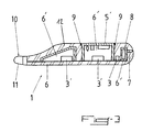
- thermometer electronic comprising a card or printed circuit supporting its functional elements and connected to a temperature sensor module ending with a probe, obtained by the previous process.
- the manufacturing process according to the invention essentially consists in having the support structure 2 carrying said functional elements 3, 3 'and being able in particular in the form of one or more card (s) or plate (s), in an injection mold 4, said support structure 2 being positioned in the mold 4 in particular by means of at least one element 5 in the form of a hood or shell attached to said structure support 2 and of which a wall portion 5 'at least rests directly against the internal face 4 ′ of said mold 4, then to be injected, after closing of the mold 4, the thermoplastic material intended to form the body 6 or a part at less than body 6 of the apparatus or instrument 1 concerned and covering fully or partially the element (s) 5 in the form of a cover or shell, with the exception of the wall (s) or portion (s) of wall (s) 5 'in contact with the internal face 4 ′ of the mold 4 of the latter (s) and, finally, after solidification of the thermoplastic material, to extract said device or instrument 1 of said mold 4.
- Element 5 can therefore, in some cases, ensure that alone the maintenance of the support structure 2 in the mold 4 and will form thus the only molded element opening onto the outer face of the device or instrument 1.
- the wall or wall portion 5 ' can achieve several functions, possibly cumulative, both technical and aesthetic.
- the wall or wall portion 5 ′ of the cover or of the shell 5 in contact with the internal face 4 'of the mold 4 may be transparent on at less part of its surface and / or have a soft and flexible texture on at least part of its surface.
- the aforementioned provisions will provide under said wall or wall portion 5 'of the indicator lights or means display, for example of the LED or LCD type, as well as means of button-type control or the like, for making a connection interactive between user and instrument or device 1, without compromise the watertightness of the latter.
- said at least one element 5 in the form of a hood or shell makes it possible to reduce the amount of thermoplastic material required for overmolding.
- said at least one element 5 attached in the form of a hood or shell constitutes with the corresponding card or plate 2, a substantially closed structure, isolating the sensitive circuit (s) or components 3 ′, in particular that or those sensitive to heat, of the hot thermoplastic material injected.
- the latter comprises also at least one insert wedging piece 7 resting against the face internal 4 'of the mold 4 closed by means of a point contact or quasi-punctual, or not, depending on whether it is expected that the end of said part wedging 7 is visible or not (see in particular Figure 1 of the drawings attached).
- the material thermoplastic 12 injected forms substantially the entire body 6 of a in one piece of the apparatus or instrument 1 and completely covers the support structure 2, the functional elements 3 and the element (s) 5 in shape of hood or shell, with the exception of the wall (s) or portion (s) of wall (s) 5 'in contact with the internal face 4' of the mold 4 of this (s) last)
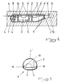
- the process can consist in reporting on the card (s) 2 several elements 5, 8 constituting closed hollow structures or forming with the card 2 closed hollow structures, at least one of which is in contact with the face internal 4 'of the mold 4 and / or at least one of which covers at least one circuit or sensitive component 3 'by isolating it from any contact with the material injected thermoplastic, intended to form the body 6.
- the element 5 in the form of hollow shell may contain substantially the entire support structure 2 and substantially delimit the volume and the external shape of the body 6, the molded thermoplastic material 12 covering only the areas of jointing and assembly of said hull.
- the latter may, as shown in Figure 5 of the drawings attached, be formed by two half-shells (upper part and lower) assembled together at an assembly line circumferential 13 via a snap connection or chicane.
- the shell-shaped element 5 presents, at its jointing and assembly areas, in particular at the level of the assembly lines 13 of its different parts constitutive, a recessed configuration or in depression compared to the external shape of the body 6 as defined by the mold 4, allowing obtain a perfect seal and mechanical strength due to the resulting thickness of overmolded material.
- each element 5 in hood or shell shape may have at its side walls 5 ", for example, in the first variant, near its wall or its wall portion 5 'in contact with the internal face 4' of the mold 4, at least a strip 9 of non-planar peripheral surface, comprising for example rib-like and groove-like conformations, forming baffles sealing.
- Such an electronic thermometer will include a card 2 supporting the electrical and electronic components 3, 3 'and a module 10 temperature sensor, connected to said card 2 and incorporating a probe corresponding.
- This module 10 is encapsulated, prior to overmolding the body 6 of the thermometer 1, in a shell 11 made of a suitable material, only a rear portion 11 ′ of said shell 11, directed towards the card 2, being overmolded by the thermoplastic material forming the body 6.
- the temperature sensor module 10 may preferably be mounted on or connected to the card or plate 2 by a rigid link and serve thus of the holding and wedging piece of said card or plate 2 in the mold 4, its part not covered by the thermoplastic material which can rest directly against the internal face of said mold 4 and be possibly pinched between the constituent parts of the latter or rest on the lower part of the shell-shaped element 5.
- the present invention also relates to an apparatus or electric or electronic instrument presenting a body resulting from a partial or total overmolding of its functional elements and obtained by through the manufacturing process described above.
- thermometer 1 comprising a card or a printed circuit 2 supporting its functional elements 3, 3 ′ and connected to a temperature sensor module 10 incorporating at least one probe.
- the body 6 of this thermometer 1 is produced by overmolding a material thermoplastic of a bio-compatible nature and said body 6 comprises at minus a hollow cavity 6 'delimited, each, on the one hand, by the card or the printed circuit 2 and, on the other hand, by an element 5 in the form of a cover or shell attached to said card or said printed circuit 2 and a portion of which wall 5 'at least is not covered by the thermoplastic material and is flush with the exterior surface 6 "of said body 6.
- the wall or wall portion or wall portion 5 'flush and not covered by the thermoplastic material forming the body 6 is at less partially flexible and / or at least partially transparent, said element 5 in the form of a hood or shell extending over at least one component or circuit 3 ′ sensitive, in particular to heat, and / or at least one light or sound signaling component or circuit, such as indicator lights, a display screen, a vibrator, a beep or the like.
- the body 6 of said thermometer 1 is essentially constituted by a element 5 in the form of a hollow shell, overmolded, at the level of the lines assembly of its constituent parts and its jointing areas with the sensor module 10 of a thermoplastic material 12, these zones or lines being, where appropriate, set back with respect to the external surface of the body 6 or at the bottom of a groove, the thermoplastic material 12 covering these areas or lines so as to constitute an external surface contiguous with the external surface of the adjacent portions of the element 5 in shell shape.
- the temperature sensor module 10 is encapsulated in a shell 11 of a suitable material of which only one end portion rear 11 ′ is covered by the thermoplastic overmolding material.
- Said rear end portion 11 ′ may also have grooves and ribs conformations, intended to allow a solid and tight connection by nesting between the body 6 surmounted and the shell 11 covering and enclosing the module 10, the material thermoplastic which can advantageously form an outer lip seal.
- This shell 11 may itself be of the overmolded type and made of a good heat conductive material.
- the molded body 6 may advantageously include several hollow cavities 6 'delimited by closed hollow elements 8 and / or in the form of a hood or shell 5 attached on said card or said printed circuit 2, at least one of which is flush with the level of the external surface 6 "of the body 6 and / or encapsulates at least one sensitive component 3 '.
- the electronic thermometer 1 above is obtained by means of the manufacturing process described above, in as a finished product come from molding and has an external shape curved, appreciably devoid of recess and gap.
Landscapes
- Physics & Mathematics (AREA)
- General Physics & Mathematics (AREA)
- Engineering & Computer Science (AREA)
- Manufacturing & Machinery (AREA)
- Mechanical Engineering (AREA)
- Injection Moulding Of Plastics Or The Like (AREA)
- Measuring Temperature Or Quantity Of Heat (AREA)
- Structures Or Materials For Encapsulating Or Coating Semiconductor Devices Or Solid State Devices (AREA)
- Casting Or Compression Moulding Of Plastics Or The Like (AREA)
- Breeding Of Plants And Reproduction By Means Of Culturing (AREA)
- Diaphragms For Electromechanical Transducers (AREA)
- Crystals, And After-Treatments Of Crystals (AREA)
- Moulding By Coating Moulds (AREA)
- Processing And Handling Of Plastics And Other Materials For Molding In General (AREA)
Applications Claiming Priority (2)
| Application Number | Priority Date | Filing Date | Title |
|---|---|---|---|
| FR9806435A FR2778817B1 (fr) | 1998-05-18 | 1998-05-18 | Procede de fabrication d'un appareil ou d'un instrument par surmoulage et appareil ou instrument ainsi obtenu |
| FR9806435 | 1998-05-18 |
Publications (2)
| Publication Number | Publication Date |
|---|---|
| EP0959334A1 true EP0959334A1 (de) | 1999-11-24 |
| EP0959334B1 EP0959334B1 (de) | 2007-07-18 |
Family
ID=9526593
Family Applications (1)
| Application Number | Title | Priority Date | Filing Date |
|---|---|---|---|
| EP99440115A Expired - Lifetime EP0959334B1 (de) | 1998-05-18 | 1999-05-18 | Verfahren zur Herstellung eines Gerätes oder eines Instruments durch Umspritzung und so erhaltenes Gerät oder Instrument |
Country Status (7)
| Country | Link |
|---|---|
| US (1) | US6319448B1 (de) |
| EP (1) | EP0959334B1 (de) |
| AT (1) | ATE367572T1 (de) |
| CA (1) | CA2272213C (de) |
| DE (1) | DE69936558T2 (de) |
| ES (1) | ES2291014T3 (de) |
| FR (1) | FR2778817B1 (de) |
Cited By (1)
| Publication number | Priority date | Publication date | Assignee | Title |
|---|---|---|---|---|
| EP1869729A4 (de) * | 2005-04-12 | 2009-07-22 | Sierra Wireless Inc | Dielektrikum-verkapselungsantenne |
Families Citing this family (14)
| Publication number | Priority date | Publication date | Assignee | Title |
|---|---|---|---|---|
| DE10005738A1 (de) * | 2000-02-09 | 2001-08-23 | Trisa Holding Ag Triengen | Verfahren zum Herstellen eines hohlen Handgriffes für Körperpflegegerät |
| DE10245086A1 (de) | 2002-09-27 | 2004-04-08 | Trisa Holding Ag | Verfahren zur Herstellung einer Zahnbürste |
| US7955543B2 (en) * | 2004-04-30 | 2011-06-07 | Medtronic, Inc. | Method of overmolding a substrate |
| CN101297443B (zh) * | 2005-10-26 | 2013-08-14 | 费德罗-莫格尔公司 | 模制灯座 |
| US7316507B2 (en) | 2005-11-03 | 2008-01-08 | Covidien Ag | Electronic thermometer with flex circuit location |
| FI20065282A7 (fi) * | 2006-05-02 | 2007-09-20 | Perlos Oyj | Menetelmä piirilevyllä varustetun kuoren valmistamiseksi |
| US7749170B2 (en) | 2007-05-22 | 2010-07-06 | Tyco Healthcare Group Lp | Multiple configurable electronic thermometer |
| US8496377B2 (en) * | 2007-12-31 | 2013-07-30 | Covidien Lp | Thermometer having molded probe component |
| US8360390B2 (en) * | 2009-01-13 | 2013-01-29 | Enphase Energy, Inc. | Method and apparatus for potting an electronic device |
| GB2500633A (en) | 2012-03-27 | 2013-10-02 | Louise Mohn | Moulding method |
| DE102016210282B4 (de) * | 2016-06-10 | 2021-05-06 | Ifm Electronic Gmbh | Elektronisches Schaltgerät und Verfahren zur Herstellung eines elektronischen Schaltgerätes |
| CN114980560B (zh) * | 2018-09-25 | 2023-08-29 | 苏州昀冢电子科技股份有限公司 | 一种具有电子元件的基座的生产工艺 |
| FR3108719B1 (fr) * | 2020-03-24 | 2022-04-08 | A Raymond Et Cie | Procédé de fabrication d’un dispositif de mesure de température destiné à être connecté à un raccord de connexion fluidique, et ensemble intermédiaire associé |
| US20250108545A1 (en) * | 2023-09-29 | 2025-04-03 | Oura Health Oy | Techniques for manufacturing a wearable ring device |
Citations (5)
| Publication number | Priority date | Publication date | Assignee | Title |
|---|---|---|---|---|
| JPS59155732A (ja) * | 1983-02-25 | 1984-09-04 | Kyushu Hitachi Maxell Ltd | 電子体温計 |
| EP0171769A2 (de) * | 1984-08-13 | 1986-02-19 | TERUMO KABUSHIKI KAISHA trading as TERUMO CORPORATION | Elektromedizinalthermometer |
| US4766095A (en) * | 1985-01-04 | 1988-08-23 | Oki Electric Industry Co., Ltd. | Method of manufacturing eprom device |
| JPS63226033A (ja) * | 1986-09-30 | 1988-09-20 | Mitsubishi Electric Corp | 光透過用窓を有する半導体装置の製造方法 |
| JPH0915060A (ja) * | 1995-07-03 | 1997-01-17 | Shichizun Denshi:Kk | 電子体温計のスイッチ構造 |
Family Cites Families (13)
| Publication number | Priority date | Publication date | Assignee | Title |
|---|---|---|---|---|
| US3981074A (en) * | 1974-08-23 | 1976-09-21 | Nitto Electric Industrial Co., Ltd. | Method for producing plastic base caps for split cavity type package semi-conductor units |
| JPS61124832A (ja) * | 1984-11-22 | 1986-06-12 | Terumo Corp | 電子体温計 |
| EP0218796B1 (de) * | 1985-08-16 | 1990-10-31 | Dai-Ichi Seiko Co. Ltd. | Halbleiteranordnung mit Packung vom Steckerstifttyp |
| US4701999A (en) * | 1985-12-17 | 1987-10-27 | Pnc, Inc. | Method of making sealed housings containing delicate structures |
| JP2874279B2 (ja) * | 1990-05-10 | 1999-03-24 | 三菱電機株式会社 | 薄型半導体装置の製造方法 |
| JP2560895B2 (ja) * | 1990-07-25 | 1996-12-04 | 三菱電機株式会社 | Icカードの製造方法およびicカード |
| US5258650A (en) * | 1991-08-26 | 1993-11-02 | Motorola, Inc. | Semiconductor device having encapsulation comprising of a thixotropic fluorosiloxane material |
| JP2602380B2 (ja) * | 1991-10-23 | 1997-04-23 | 富士通株式会社 | 半導体装置及びその製造方法 |
| JPH0766331A (ja) * | 1993-08-02 | 1995-03-10 | Motorola Inc | 半導体デバイス・パッケージの製造方法 |
| US5420752A (en) * | 1993-08-18 | 1995-05-30 | Lsi Logic Corporation | GPT system for encapsulating an integrated circuit package |
| US5458716A (en) * | 1994-05-25 | 1995-10-17 | Texas Instruments Incorporated | Methods for manufacturing a thermally enhanced molded cavity package having a parallel lid |
| JP3337847B2 (ja) * | 1995-02-27 | 2002-10-28 | 株式会社東芝 | 電子部品内蔵カードの製造方法 |
| DE69627643D1 (de) * | 1996-06-28 | 2003-05-28 | St Microelectronics Srl | Verfahren zur Herstellung einer Plastikpackung für eine elektronische Anordnung mit vollständig isolierter Wärmesenke |
-
1998
- 1998-05-18 FR FR9806435A patent/FR2778817B1/fr not_active Expired - Fee Related
-
1999
- 1999-05-18 DE DE69936558T patent/DE69936558T2/de not_active Expired - Lifetime
- 1999-05-18 US US09/313,739 patent/US6319448B1/en not_active Expired - Lifetime
- 1999-05-18 AT AT99440115T patent/ATE367572T1/de not_active IP Right Cessation
- 1999-05-18 EP EP99440115A patent/EP0959334B1/de not_active Expired - Lifetime
- 1999-05-18 CA CA002272213A patent/CA2272213C/fr not_active Expired - Fee Related
- 1999-05-18 ES ES99440115T patent/ES2291014T3/es not_active Expired - Lifetime
Patent Citations (5)
| Publication number | Priority date | Publication date | Assignee | Title |
|---|---|---|---|---|
| JPS59155732A (ja) * | 1983-02-25 | 1984-09-04 | Kyushu Hitachi Maxell Ltd | 電子体温計 |
| EP0171769A2 (de) * | 1984-08-13 | 1986-02-19 | TERUMO KABUSHIKI KAISHA trading as TERUMO CORPORATION | Elektromedizinalthermometer |
| US4766095A (en) * | 1985-01-04 | 1988-08-23 | Oki Electric Industry Co., Ltd. | Method of manufacturing eprom device |
| JPS63226033A (ja) * | 1986-09-30 | 1988-09-20 | Mitsubishi Electric Corp | 光透過用窓を有する半導体装置の製造方法 |
| JPH0915060A (ja) * | 1995-07-03 | 1997-01-17 | Shichizun Denshi:Kk | 電子体温計のスイッチ構造 |
Non-Patent Citations (3)
| Title |
|---|
| PATENT ABSTRACTS OF JAPAN vol. 009, no. 006 (P - 326) 11 January 1985 (1985-01-11) * |
| PATENT ABSTRACTS OF JAPAN vol. 013, no. 018 (E - 704) 17 January 1989 (1989-01-17) * |
| PATENT ABSTRACTS OF JAPAN vol. 097, no. 005 30 May 1997 (1997-05-30) * |
Cited By (1)
| Publication number | Priority date | Publication date | Assignee | Title |
|---|---|---|---|---|
| EP1869729A4 (de) * | 2005-04-12 | 2009-07-22 | Sierra Wireless Inc | Dielektrikum-verkapselungsantenne |
Also Published As
| Publication number | Publication date |
|---|---|
| DE69936558T2 (de) | 2008-03-20 |
| FR2778817A1 (fr) | 1999-11-19 |
| CA2272213C (fr) | 2009-02-17 |
| ATE367572T1 (de) | 2007-08-15 |
| US6319448B1 (en) | 2001-11-20 |
| CA2272213A1 (fr) | 1999-11-18 |
| EP0959334B1 (de) | 2007-07-18 |
| FR2778817B1 (fr) | 2000-06-30 |
| DE69936558D1 (de) | 2007-08-30 |
| ES2291014T3 (es) | 2008-02-16 |
Similar Documents
| Publication | Publication Date | Title |
|---|---|---|
| CA2272213C (fr) | Procede de fabrication d'un appareil ou d'un instrument par surmoulage et appareil ou instrument ainsi obtenu | |
| EP2743786B1 (de) | Tragbare elektronische Vorrichtung und Herstellungsverfahren einer solchen Vorrichtung | |
| EP1894848B1 (de) | Vorrichtung zum Verpacken mit Doppelhülle | |
| EP2805649B1 (de) | Kochtopf, der ein dichtes Steuermodul umfasst | |
| WO2012120066A1 (fr) | Contenant, notamment pot de produit cosmetique, et procede de fabrication associe | |
| FR2463436A1 (fr) | Montre a elements de forme profilee, notamment non circulaire | |
| FR2518748A1 (fr) | Thermometre medical electronique | |
| EP2805650B1 (de) | Kochtopf, der ein dichtes Gehäuse umfasst | |
| FR2812599A1 (fr) | Structure de poignee pour vehicules, en particulier pour l'eclairage de la plaque posterieure sur les automobiles | |
| EP1284335B1 (de) | Türgriff mit Elektronikmodul insbesondere für Kraftfahrzeuge | |
| FR2548954A1 (fr) | Procede pour realiser une enceinte etanche | |
| FR2723202A1 (fr) | Capteur de grandeur physique, notamment un capteurde temperature | |
| CH413711A (fr) | Procédé de fabrication d'un récipient et produit obtenu | |
| FR3035667A1 (fr) | Appareil electromenager de repassage comportant un generateur de vapeur muni d'un orifice de vidange | |
| FR2703838A1 (fr) | Vitrage muni d'un élément de connexion. | |
| EP1203907A1 (de) | Kugelrückschlagventil | |
| WO2007077361A2 (fr) | Buse de distribution de produit fluide, dispositif de distribution comprenant un telle buse et procede de fabrication | |
| EP2373549B1 (de) | Verpackung mit veränderlichem aussehen | |
| EP1405796B1 (de) | Abgabevorrichtung für Flüssigkeiten | |
| EP1293760A1 (de) | Verfahren zum Herstellen von Bauteilen von Flüssigkeitszählern aus kunststoff und Bauteile von Flüssigkeitszählern hergestellt mit einem solchen Verfahren | |
| EP3669714B1 (de) | Dichter elektrisch isolierter wasserkocher, der unter wasser gereinigt werden kann | |
| FR2756347A1 (fr) | Vanne a boisseau cylindrique | |
| FR2500597A1 (fr) | Capteur solaire dit " monolithe " et son procede de fabrication | |
| EP0836170B1 (de) | Parfümprobenständer | |
| FR2656596A1 (fr) | Barquette auto-chauffante. |
Legal Events
| Date | Code | Title | Description |
|---|---|---|---|
| PUAI | Public reference made under article 153(3) epc to a published international application that has entered the european phase |
Free format text: ORIGINAL CODE: 0009012 |
|
| AK | Designated contracting states |
Kind code of ref document: A1 Designated state(s): AT BE CH DE DK ES FI FR GB GR IE IT LI NL PT SE |
|
| AX | Request for extension of the european patent |
Free format text: AL;LT;LV;MK;RO;SI |
|
| 17P | Request for examination filed |
Effective date: 20000522 |
|
| AKX | Designation fees paid |
Free format text: AT BE CH DE DK ES FI FR GB GR IE IT LI NL PT SE |
|
| GRAP | Despatch of communication of intention to grant a patent |
Free format text: ORIGINAL CODE: EPIDOSNIGR1 |
|
| GRAS | Grant fee paid |
Free format text: ORIGINAL CODE: EPIDOSNIGR3 |
|
| GRAA | (expected) grant |
Free format text: ORIGINAL CODE: 0009210 |
|
| AK | Designated contracting states |
Kind code of ref document: B1 Designated state(s): AT BE CH DE DK ES FI FR GB GR IE IT LI NL PT SE |
|
| REG | Reference to a national code |
Ref country code: GB Ref legal event code: FG4D Free format text: NOT ENGLISH |
|
| REG | Reference to a national code |
Ref country code: CH Ref legal event code: EP |
|
| REF | Corresponds to: |
Ref document number: 69936558 Country of ref document: DE Date of ref document: 20070830 Kind code of ref document: P |
|
| REG | Reference to a national code |
Ref country code: IE Ref legal event code: FG4D Free format text: LANGUAGE OF EP DOCUMENT: FRENCH |
|
| GBT | Gb: translation of ep patent filed (gb section 77(6)(a)/1977) |
Effective date: 20071029 |
|
| REG | Reference to a national code |
Ref country code: CH Ref legal event code: NV Representative=s name: SCHNEIDER FELDMANN AG PATENT- UND MARKENANWAELTE |
|
| PG25 | Lapsed in a contracting state [announced via postgrant information from national office to epo] |
Ref country code: PT Free format text: LAPSE BECAUSE OF FAILURE TO SUBMIT A TRANSLATION OF THE DESCRIPTION OR TO PAY THE FEE WITHIN THE PRESCRIBED TIME-LIMIT Effective date: 20071218 Ref country code: NL Free format text: LAPSE BECAUSE OF FAILURE TO SUBMIT A TRANSLATION OF THE DESCRIPTION OR TO PAY THE FEE WITHIN THE PRESCRIBED TIME-LIMIT Effective date: 20070718 Ref country code: FI Free format text: LAPSE BECAUSE OF FAILURE TO SUBMIT A TRANSLATION OF THE DESCRIPTION OR TO PAY THE FEE WITHIN THE PRESCRIBED TIME-LIMIT Effective date: 20070718 |
|
| NLV1 | Nl: lapsed or annulled due to failure to fulfill the requirements of art. 29p and 29m of the patents act | ||
| REG | Reference to a national code |
Ref country code: ES Ref legal event code: FG2A Ref document number: 2291014 Country of ref document: ES Kind code of ref document: T3 |
|
| PG25 | Lapsed in a contracting state [announced via postgrant information from national office to epo] |
Ref country code: AT Free format text: LAPSE BECAUSE OF FAILURE TO SUBMIT A TRANSLATION OF THE DESCRIPTION OR TO PAY THE FEE WITHIN THE PRESCRIBED TIME-LIMIT Effective date: 20070718 |
|
| REG | Reference to a national code |
Ref country code: IE Ref legal event code: FD4D |
|
| PG25 | Lapsed in a contracting state [announced via postgrant information from national office to epo] |
Ref country code: GR Free format text: LAPSE BECAUSE OF FAILURE TO SUBMIT A TRANSLATION OF THE DESCRIPTION OR TO PAY THE FEE WITHIN THE PRESCRIBED TIME-LIMIT Effective date: 20071019 Ref country code: DK Free format text: LAPSE BECAUSE OF FAILURE TO SUBMIT A TRANSLATION OF THE DESCRIPTION OR TO PAY THE FEE WITHIN THE PRESCRIBED TIME-LIMIT Effective date: 20070718 |
|
| PLBE | No opposition filed within time limit |
Free format text: ORIGINAL CODE: 0009261 |
|
| STAA | Information on the status of an ep patent application or granted ep patent |
Free format text: STATUS: NO OPPOSITION FILED WITHIN TIME LIMIT |
|
| PG25 | Lapsed in a contracting state [announced via postgrant information from national office to epo] |
Ref country code: IE Free format text: LAPSE BECAUSE OF FAILURE TO SUBMIT A TRANSLATION OF THE DESCRIPTION OR TO PAY THE FEE WITHIN THE PRESCRIBED TIME-LIMIT Effective date: 20070718 |
|
| 26N | No opposition filed |
Effective date: 20080421 |
|
| PG25 | Lapsed in a contracting state [announced via postgrant information from national office to epo] |
Ref country code: SE Free format text: LAPSE BECAUSE OF FAILURE TO SUBMIT A TRANSLATION OF THE DESCRIPTION OR TO PAY THE FEE WITHIN THE PRESCRIBED TIME-LIMIT Effective date: 20071018 |
|
| REG | Reference to a national code |
Ref country code: FR Ref legal event code: PLFP Year of fee payment: 18 |
|
| PGFP | Annual fee paid to national office [announced via postgrant information from national office to epo] |
Ref country code: DE Payment date: 20160531 Year of fee payment: 18 Ref country code: GB Payment date: 20160513 Year of fee payment: 18 Ref country code: ES Payment date: 20160520 Year of fee payment: 18 |
|
| PGFP | Annual fee paid to national office [announced via postgrant information from national office to epo] |
Ref country code: BE Payment date: 20160527 Year of fee payment: 18 Ref country code: FR Payment date: 20160518 Year of fee payment: 18 Ref country code: IT Payment date: 20160512 Year of fee payment: 18 |
|
| PGFP | Annual fee paid to national office [announced via postgrant information from national office to epo] |
Ref country code: CH Payment date: 20160829 Year of fee payment: 18 |
|
| REG | Reference to a national code |
Ref country code: DE Ref legal event code: R119 Ref document number: 69936558 Country of ref document: DE |
|
| REG | Reference to a national code |
Ref country code: CH Ref legal event code: PL |
|
| GBPC | Gb: european patent ceased through non-payment of renewal fee |
Effective date: 20170518 |
|
| PG25 | Lapsed in a contracting state [announced via postgrant information from national office to epo] |
Ref country code: LI Free format text: LAPSE BECAUSE OF NON-PAYMENT OF DUE FEES Effective date: 20170531 Ref country code: CH Free format text: LAPSE BECAUSE OF NON-PAYMENT OF DUE FEES Effective date: 20170531 |
|
| REG | Reference to a national code |
Ref country code: FR Ref legal event code: ST Effective date: 20180131 |
|
| REG | Reference to a national code |
Ref country code: BE Ref legal event code: MM Effective date: 20170531 |
|
| PG25 | Lapsed in a contracting state [announced via postgrant information from national office to epo] |
Ref country code: GB Free format text: LAPSE BECAUSE OF NON-PAYMENT OF DUE FEES Effective date: 20170518 Ref country code: DE Free format text: LAPSE BECAUSE OF NON-PAYMENT OF DUE FEES Effective date: 20171201 |
|
| PG25 | Lapsed in a contracting state [announced via postgrant information from national office to epo] |
Ref country code: FR Free format text: LAPSE BECAUSE OF NON-PAYMENT OF DUE FEES Effective date: 20170531 Ref country code: IT Free format text: LAPSE BECAUSE OF NON-PAYMENT OF DUE FEES Effective date: 20170518 |
|
| REG | Reference to a national code |
Ref country code: ES Ref legal event code: FD2A Effective date: 20180629 |
|
| PG25 | Lapsed in a contracting state [announced via postgrant information from national office to epo] |
Ref country code: ES Free format text: LAPSE BECAUSE OF NON-PAYMENT OF DUE FEES Effective date: 20170519 |
|
| PG25 | Lapsed in a contracting state [announced via postgrant information from national office to epo] |
Ref country code: BE Free format text: LAPSE BECAUSE OF NON-PAYMENT OF DUE FEES Effective date: 20170531 |