EP0959289A1 - Verbindungsvorrichtung zum Verbinden eines Rohres an eine Schnittstelle - Google Patents
Verbindungsvorrichtung zum Verbinden eines Rohres an eine Schnittstelle Download PDFInfo
- Publication number
- EP0959289A1 EP0959289A1 EP99440088A EP99440088A EP0959289A1 EP 0959289 A1 EP0959289 A1 EP 0959289A1 EP 99440088 A EP99440088 A EP 99440088A EP 99440088 A EP99440088 A EP 99440088A EP 0959289 A1 EP0959289 A1 EP 0959289A1
- Authority
- EP
- European Patent Office
- Prior art keywords
- interface
- tube
- rigid
- parts
- rear part
- Prior art date
- Legal status (The legal status is an assumption and is not a legal conclusion. Google has not performed a legal analysis and makes no representation as to the accuracy of the status listed.)
- Withdrawn
Links
- 230000008878 coupling Effects 0.000 title 1
- 238000010168 coupling process Methods 0.000 title 1
- 238000005859 coupling reaction Methods 0.000 title 1
- 239000000463 material Substances 0.000 claims abstract description 19
- 239000004033 plastic Substances 0.000 claims abstract description 10
- 229920003023 plastic Polymers 0.000 claims abstract description 10
- 238000007789 sealing Methods 0.000 claims description 8
- 238000002347 injection Methods 0.000 claims description 3
- 239000007924 injection Substances 0.000 claims description 3
- 239000012815 thermoplastic material Substances 0.000 claims description 2
- 238000003466 welding Methods 0.000 claims description 2
- 229920001971 elastomer Polymers 0.000 description 6
- 239000005060 rubber Substances 0.000 description 6
- 240000007817 Olea europaea Species 0.000 description 4
- 239000011324 bead Substances 0.000 description 4
- 235000008331 Pinus X rigitaeda Nutrition 0.000 description 2
- 235000011613 Pinus brutia Nutrition 0.000 description 2
- 241000018646 Pinus brutia Species 0.000 description 2
- 230000032683 aging Effects 0.000 description 2
- 238000001816 cooling Methods 0.000 description 2
- 239000012530 fluid Substances 0.000 description 2
- 239000000446 fuel Substances 0.000 description 2
- 239000002184 metal Substances 0.000 description 2
- 229920002994 synthetic fiber Polymers 0.000 description 2
- 239000004952 Polyamide Substances 0.000 description 1
- 150000001408 amides Chemical class 0.000 description 1
- 230000000295 complement effect Effects 0.000 description 1
- 229920002457 flexible plastic Polymers 0.000 description 1
- 238000004519 manufacturing process Methods 0.000 description 1
- 230000004048 modification Effects 0.000 description 1
- 238000012986 modification Methods 0.000 description 1
- 229920002647 polyamide Polymers 0.000 description 1
- 229920000570 polyether Polymers 0.000 description 1
- 229920002725 thermoplastic elastomer Polymers 0.000 description 1
- 239000002699 waste material Substances 0.000 description 1
- 230000004584 weight gain Effects 0.000 description 1
- 235000019786 weight gain Nutrition 0.000 description 1
Images

Classifications
-
- F—MECHANICAL ENGINEERING; LIGHTING; HEATING; WEAPONS; BLASTING
- F16—ENGINEERING ELEMENTS AND UNITS; GENERAL MEASURES FOR PRODUCING AND MAINTAINING EFFECTIVE FUNCTIONING OF MACHINES OR INSTALLATIONS; THERMAL INSULATION IN GENERAL
- F16L—PIPES; JOINTS OR FITTINGS FOR PIPES; SUPPORTS FOR PIPES, CABLES OR PROTECTIVE TUBING; MEANS FOR THERMAL INSULATION IN GENERAL
- F16L33/00—Arrangements for connecting hoses to rigid members; Rigid hose-connectors, i.e. single members engaging both hoses
- F16L33/20—Undivided rings, sleeves, or like members contracted on the hose or expanded inside the hose by means of tools; Arrangements using such members
- F16L33/213—Undivided rings, sleeves, or like members contracted on the hose or expanded inside the hose by means of tools; Arrangements using such members only a sleeve being expanded inside the hose
-
- F—MECHANICAL ENGINEERING; LIGHTING; HEATING; WEAPONS; BLASTING
- F16—ENGINEERING ELEMENTS AND UNITS; GENERAL MEASURES FOR PRODUCING AND MAINTAINING EFFECTIVE FUNCTIONING OF MACHINES OR INSTALLATIONS; THERMAL INSULATION IN GENERAL
- F16L—PIPES; JOINTS OR FITTINGS FOR PIPES; SUPPORTS FOR PIPES, CABLES OR PROTECTIVE TUBING; MEANS FOR THERMAL INSULATION IN GENERAL
- F16L33/00—Arrangements for connecting hoses to rigid members; Rigid hose-connectors, i.e. single members engaging both hoses
- F16L33/30—Arrangements for connecting hoses to rigid members; Rigid hose-connectors, i.e. single members engaging both hoses comprising parts inside the hoses only
Definitions
- the present invention relates to a connection device for connecting a plastic tube on an interface with a shaped tip made in a rigid material, comprising a rigid rear part having members attachment and sealing to attach to the plastic tube.
- connection device is generally used in the circuits of transfer of fluids (cooling, fuel, etc.) from a motor vehicle.
- rubber tubes have so far been used which are connected interface to another and held together by metal collars.
- the shape of the tip rigid of these interfaces is often specific. It can be for example olive or conical. It is generally imposed by the supplier of the part on which is grafted the interface. It is specified that any connection or connection on which must be mounted the rubber tube.
- a tube rigid in synthetic material we equip it with a "relay" part mounted in force and which is receiving a sleeve or a small rubber tube so to liaise.
- two metal collars are used to clamp the tube or the end caps.
- plastics can replace rubbers for reasons for weight gain and price. It also improves the parts aging. The major problem lies in the connection because the plastics are not as flexible or deformable as rubbers.
- connection devices made in one piece in one rigid material, as described in the publications FR-A-1 160 833 and US-A-4 664 423.
- these devices have at the end rear of the hooking members and at the front end a thread so that it can be screwed onto the rigid element.
- These devices cannot therefore be used in all cases.
- no thread is provided at the front end, it is not possible to mount a rigid element there since the part front is itself rigid. In this case, it is not possible to connect a tube semi-rigid on a rigid interface too.
- the present invention aims to overcome these drawbacks by proposing a device for simplified connection, particularly quick to assemble, inexpensive and which in all the cases can be mounted on a rigid element such as a shaped end piece.
- connection device of the type indicated in preamble, characterized in that it comprises a front part made in a flexible material and constituting a sleeve arranged to be mounted around the rigid interface.
- the rear part is mounted inside the tube.
- the attachment and sealing members may consist of notches having in cross section the shape of a fir tree or any other prominence allowing good attachment and good sealing.
- the rear part can be made of a hard thermoplastic material.
- the materials used have good aptitudes for combined aging automotive temperature / fluid for which they were selected.
- the front and rear parts can be assembled by welding or made in one piece by bi-material injection.
- the front and rear parts can be produced in the same flexible material, the rear part being stiffened by means of an insert.
- the device comprises a stop provided between the parts front and rear.
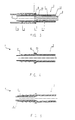
- connection device 1 comprises a part rear 2 and a front part 3.
- the rear part 2 is mounted inside a tube 5 made of synthetic material.
- This tube 5 replaces the rubber sleeves used especially in cooling circuits or those used at the end of fuel lines.
- the rear part 2 consists of a hollow cylinder made of hard plastic. It has along its outer surface notches 4 having in cross section the shape of a fir tree, said notches constituting hooking and sealing members allowing the connection device 1 to be rigidly assembled to the tube 5.
- the notches 4 will be called “pine notches”.
- the attachment members may be constituted by other devices than the pine notches, for example "Double Bead”.
- the maximum diameter of a notch 4 is greater than the inside diameter of tube 5 by so as to be inserted in force.
- annular bead 6 which constitutes a stop on which the end of the tube 5 comes to bear when inserting the connection device 1. This bead 6 also makes it possible to reinforce the tightness from the whole.
- the front part 3 constitutes a sleeve 7 mounted around an interface 8.
- This interface has an olive-shaped tip 9 and is made of a rigid material.
- the sleeve 7 has the shape of a hollow cylinder made of a flexible plastic material.
- the inner face 10 of the end of the sleeve 7 connected to the rear part 2 is curved so as to have a complementary shape to the olive tip 9. It is well evident that the inner face 10 can be of a very specific shape so as to adapt to all interfaces.
- the inside diameter of the sleeve 7 is slightly smaller than the outside diameter of the interface 8 so that the latter is inserted in force in the sleeve 7.
- the end 11 of the sleeve 7 has a chamfer 12 for facilitate the introduction of the interface 8.
- connection device i is produced in a single part by bi-material injection.
- connection device 1 Due to the rear part 2 made of a hard material. the connection device 1 is sufficiently resistant to tearing. Thanks to the front part 3 made in a flexible material, the connection device 1 is easily mounted.
- the device connection 1 allows to directly connect the plastic tube 5 with the interface 8 with olive tip 9. The sealing is ensured by the force assembly of the sprockets 4 in the tube 5 and the sleeve 7 in the interface 8.
- the assembly of the connection device 1 with interface 8 can be reinforced with a spring clip so that the connection of the device with the olive tip 9 is removable at all moment.
- the rear 2 and front 3 parts are assembled by means of a mirror weld 13 provided between the bead 6 and the part before 3.
- the rear 2 and front 3 parts are made in one piece from the same flexible material.
- the rear part 2 is stiffened by means of an insert 14 placed inside.
- the present invention is not limited to the embodiments described but extends to any modification and variant obvious to a person skilled in the art.
- the choice of materials for the front and rear parts is not exhaustive.
- the invention can be applied to any type of connection between a tube or pipe flexible and a more rigid tube / interface.
Landscapes
- Engineering & Computer Science (AREA)
- General Engineering & Computer Science (AREA)
- Mechanical Engineering (AREA)
- Quick-Acting Or Multi-Walled Pipe Joints (AREA)
Applications Claiming Priority (2)
| Application Number | Priority Date | Filing Date | Title |
|---|---|---|---|
| FR9805213 | 1998-04-22 | ||
| FR9805213A FR2777971A1 (fr) | 1998-04-22 | 1998-04-22 | Dispositif de connexion pour le raccordement d'un tube sur un interface |
Publications (1)
| Publication Number | Publication Date |
|---|---|
| EP0959289A1 true EP0959289A1 (de) | 1999-11-24 |
Family
ID=9525681
Family Applications (1)
| Application Number | Title | Priority Date | Filing Date |
|---|---|---|---|
| EP99440088A Withdrawn EP0959289A1 (de) | 1998-04-22 | 1999-04-22 | Verbindungsvorrichtung zum Verbinden eines Rohres an eine Schnittstelle |
Country Status (2)
| Country | Link |
|---|---|
| EP (1) | EP0959289A1 (de) |
| FR (1) | FR2777971A1 (de) |
Cited By (1)
| Publication number | Priority date | Publication date | Assignee | Title |
|---|---|---|---|---|
| EP1188977A1 (de) | 2000-09-19 | 2002-03-20 | Siemens Building Technologies AG | Anschlussrohr für einen Schlauch |
Families Citing this family (1)
| Publication number | Priority date | Publication date | Assignee | Title |
|---|---|---|---|---|
| WO2017071849A1 (de) * | 2015-10-29 | 2017-05-04 | Norma Germany Gmbh | Verbinder für eine fluidleitung |
Citations (3)
| Publication number | Priority date | Publication date | Assignee | Title |
|---|---|---|---|---|
| FR1160833A (fr) | 1956-11-13 | 1958-08-11 | Embout cannelé pour raccorder des tuyaux | |
| US4603890A (en) * | 1984-12-06 | 1986-08-05 | Robert Huppee | Barbed tubing connector |
| US4664423A (en) | 1984-06-15 | 1987-05-12 | Rowley William W | Polybutylene tube coupling and method for making it |
-
1998
- 1998-04-22 FR FR9805213A patent/FR2777971A1/fr active Pending
-
1999
- 1999-04-22 EP EP99440088A patent/EP0959289A1/de not_active Withdrawn
Patent Citations (3)
| Publication number | Priority date | Publication date | Assignee | Title |
|---|---|---|---|---|
| FR1160833A (fr) | 1956-11-13 | 1958-08-11 | Embout cannelé pour raccorder des tuyaux | |
| US4664423A (en) | 1984-06-15 | 1987-05-12 | Rowley William W | Polybutylene tube coupling and method for making it |
| US4603890A (en) * | 1984-12-06 | 1986-08-05 | Robert Huppee | Barbed tubing connector |
Cited By (1)
| Publication number | Priority date | Publication date | Assignee | Title |
|---|---|---|---|---|
| EP1188977A1 (de) | 2000-09-19 | 2002-03-20 | Siemens Building Technologies AG | Anschlussrohr für einen Schlauch |
Also Published As
| Publication number | Publication date |
|---|---|
| FR2777971A1 (fr) | 1999-10-29 |
Similar Documents
| Publication | Publication Date | Title |
|---|---|---|
| EP1497582B1 (de) | Undurchlässige verbindungsvorrichtung, insbesondere für das motorlufteinlasssystem eines kraftfahrzeugs | |
| FR2713305A1 (fr) | Dispositif de raccord rapide pour tubulures d'échangeur de chaleur. | |
| FR2845149A1 (fr) | Dispositif et structure anti-rotation pour tuyau et raccord | |
| FR2803649A1 (fr) | Dispositif de connexion | |
| FR2665507A1 (fr) | Dispositif pour l'assemblage rapide d'une durite a un echangeur de chaleur d'un vehicule automobile. | |
| WO1999050583A1 (fr) | Raccord encliquetable pour tuyaux | |
| FR2749639A1 (fr) | Dispositif de raccord rapide pour conduit de fluide sous pression | |
| FR2829554A1 (fr) | Raccord encliquetable monocorps | |
| FR2514453A1 (fr) | Joint pour tubes en matiere elastomere | |
| FR2663080A1 (fr) | Ensemble formant raccord d'accouplement pour circuits de refrigerant de moteur de vehicule. | |
| EP0740101B1 (de) | Schnellkupplung mit einem selbständig belasteten Ventil | |
| FR2640723A1 (fr) | Tuyauteries de raccordement, et faisceaux composes de telles tuyauteries | |
| EP1055079B1 (de) | Rohrförmiges element mit einem starren und einem nachgiebigen querteil in einem stück für eine rohrleitung | |
| FR2795155A1 (fr) | Dispositif de raccord etanche pour conduit de fluide, en particulier pour vehicule automobile | |
| EP0627592B1 (de) | Schnellkupplung | |
| FR2591309A1 (fr) | Raccord hydraulique a branchement manuel rapide pour canalisation de fluide | |
| FR2646697A1 (fr) | Dispositif d'assemblage par encliquetage pour echangeurs de chaleur de vehicules automobiles | |
| FR2687757A1 (fr) | Accouplement emboitable pour relier des conduits parcourus par un fluide. | |
| EP0197874B1 (de) | Elastisches Hakenelement für Schnellverbindungssysteme bei Flüssigkeitsleitungen | |
| FR2938038A1 (fr) | Element d'etancheite sans zone de retention et dispositif de raccordement comportant un tel element d'etancheite | |
| FR2777971A1 (fr) | Dispositif de connexion pour le raccordement d'un tube sur un interface | |
| FR2777972A1 (fr) | Dispositif de connexion pour le raccordement d'un tube sur un interface | |
| EP0327441B1 (de) | Wärmetauscher | |
| FR2822519A1 (fr) | Raccord pour tuyau | |
| FR2674491A1 (fr) | Dispositif de positionnement pour raccords de canalisations d'installations hydrauliques pour vehicules automobiles, notamment pour groupes de servodirection hydraulique. |
Legal Events
| Date | Code | Title | Description |
|---|---|---|---|
| PUAI | Public reference made under article 153(3) epc to a published international application that has entered the european phase |
Free format text: ORIGINAL CODE: 0009012 |
|
| AK | Designated contracting states |
Kind code of ref document: A1 Designated state(s): DE ES FR GB IT |
|
| AX | Request for extension of the european patent |
Free format text: AL;LT;LV;MK;RO;SI |
|
| AKX | Designation fees paid | ||
| REG | Reference to a national code |
Ref country code: DE Ref legal event code: 8566 |
|
| 17P | Request for examination filed |
Effective date: 20000722 |
|
| RBV | Designated contracting states (corrected) |
Designated state(s): DE ES FR GB IT |
|
| STAA | Information on the status of an ep patent application or granted ep patent |
Free format text: STATUS: THE APPLICATION IS DEEMED TO BE WITHDRAWN |
|
| 18D | Application deemed to be withdrawn |
Effective date: 20011101 |