EP0959264A2 - Amortisseur hydraulique et sa méthode de montage - Google Patents
Amortisseur hydraulique et sa méthode de montage Download PDFInfo
- Publication number
- EP0959264A2 EP0959264A2 EP99105803A EP99105803A EP0959264A2 EP 0959264 A2 EP0959264 A2 EP 0959264A2 EP 99105803 A EP99105803 A EP 99105803A EP 99105803 A EP99105803 A EP 99105803A EP 0959264 A2 EP0959264 A2 EP 0959264A2
- Authority
- EP
- European Patent Office
- Prior art keywords
- outer cylinder
- vibration damper
- piston
- spring
- hydraulic vibration
- Prior art date
- Legal status (The legal status is an assumption and is not a legal conclusion. Google has not performed a legal analysis and makes no representation as to the accuracy of the status listed.)
- Withdrawn
Links
Images

Classifications
-
- F—MECHANICAL ENGINEERING; LIGHTING; HEATING; WEAPONS; BLASTING
- F16—ENGINEERING ELEMENTS AND UNITS; GENERAL MEASURES FOR PRODUCING AND MAINTAINING EFFECTIVE FUNCTIONING OF MACHINES OR INSTALLATIONS; THERMAL INSULATION IN GENERAL
- F16F—SPRINGS; SHOCK-ABSORBERS; MEANS FOR DAMPING VIBRATION
- F16F9/00—Springs, vibration-dampers, shock-absorbers, or similarly-constructed movement-dampers using a fluid or the equivalent as damping medium
- F16F9/32—Details
- F16F9/3207—Constructional features
- F16F9/3235—Constructional features of cylinders
- F16F9/3242—Constructional features of cylinders of cylinder ends, e.g. caps
-
- F—MECHANICAL ENGINEERING; LIGHTING; HEATING; WEAPONS; BLASTING
- F16—ENGINEERING ELEMENTS AND UNITS; GENERAL MEASURES FOR PRODUCING AND MAINTAINING EFFECTIVE FUNCTIONING OF MACHINES OR INSTALLATIONS; THERMAL INSULATION IN GENERAL
- F16F—SPRINGS; SHOCK-ABSORBERS; MEANS FOR DAMPING VIBRATION
- F16F9/00—Springs, vibration-dampers, shock-absorbers, or similarly-constructed movement-dampers using a fluid or the equivalent as damping medium
- F16F9/32—Details
- F16F9/36—Special sealings, including sealings or guides for piston-rods
Definitions
- the invention relates to a hydraulic vibration damper according to the preamble of claim 1.
- the vibration damper In the case of hydraulic vibration dampers, be it single-tube or two-tube vibration dampers, it is necessary, in addition to the installation of the built-in parts, the vibration damper also to be filled with damping fluid and with single-tube vibration dampers to fill an equalization chamber with gas beyond the separating piston. Furthermore, the oscillating piston rod must be sealed on the outlet side at one end and be led. So here is a suitable seal and guide package to use.
- the invention has for its object generic hydraulic vibration damper to be designed in such a way that the assembly is considerably simplified and a method of assembling such a vibration damper find that meets the above conditions.
- This object is achieved according to the invention by a hydraulic vibration damper with the characteristics of Claim 1 solved.
- Advantageous training and further training are in the claims 2 to 6 described.
- Claim 7 describes an inventive method for Assembly of a generic vibration damper and claim 8 describes an advantageous method.
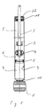
- Hydraulic vibration dampers are used in cooperation with springs resilient and damping suspension of the wheels in relation to the vehicle Motor vehicles used. Your connection to the wheel suspension and vehicle body takes place via stop parts 1.
- stop part 1 which is attached to the end of the outer cylinder 2, shown.
- a Another stop part is usually provided at the end of the piston rod 3.
- a damper piston 4 attached at the end of the piston rod 3.
- This damper piston 4 separates the damping fluid filled interior of the outer cylinder 2 in two work rooms 5, 6. Suitable, Valves, not shown, on the damper piston 4 cause the damping of the oscillating movement of the damper piston connected to the piston rod 3 4.
- a compensation chamber for single-tube vibration dampers 7 provided which is filled with gas.
- This gas-filled compensation chamber 7 is opposite the working rooms 5 and 6 filled with damping fluid via a axially displaceable separating piston 8 separated.
- the separating piston 8 is on his Outer periphery formed with a radial seal that seals against the Inner jacket 9 of the outer cylinder 2 causes.
- the outer cylinder 2 is formed with a bottom 10 and an open end.
- the stop part 1 connects to the bottom 10 of the outer cylinder 2.
- the piston rod 3 which on its immersed end carries the damper piston 4.
- a seal and guide package 11 serves for the radial sliding guiding of the piston rod 3 and Sealing of the working space 5 filled with damping fluid to the outside.
- the 11 oscillating piston rod 3 must be sufficiently lubricated, but one if possible little loss of working fluid should be provided to the outside to achieve a long service life for the vibration damper.
- FIG. 2 shows an enlarged illustration of the area of the sealing and guiding package 11 on the vibration damper.
- the representation is chosen so that the Seal and guide package 11 not yet its during assembly has taken the final assembly position.
- the seal and guide package 11 is in the axial direction with respect to the outer cylinder 2 via two spring washers 12, 13 held in two in the inner jacket 9 of the outer cylinder 2 Grooves 14, 15 engage and the outer jacket 16 of the seal and guide package 11 reach over inside.
- the spring washers 12, 13 have a circumference Separation point so that they can be pushed together radially inwards and have a circular cross-section opposite the seal and Guide package 11 in the inner jacket 9 of the outer cylinder 2 groove 15 for receiving the inner spring ring 13 is introduced approximately semicircular.
- the groove 14 to accommodate the outer spring ring 12 is designed so that it is End 17 of the outer cylinder 2 also circular according to the shape of the Spring rings 12 is formed, wherein it forms approximately the shape of a quarter circle. In In the axially opposite direction, however, the groove 14 tapers approximately conically towards the inner jacket 9 of the outer cylinder 2. This shape of the outer groove 14 brings significant advantages for the entire assembly of the vibration damper.
- the inner groove 15 can, if it makes sense, be formed with this shape.
- the outer cylinder 2 is completely empty in the mounting device or Assembly machine introduced. All installation parts are in the upper tool 18, which is supported on the end 17 of the outer cylinder 2 in a radially and axially guided manner. A stamp 19 is provided above all of the built-in parts and holds the built-in parts can slide one after the other into the interior of the outer cylinder 2.
- the outer cylinder 2 is filled with gas. After that is done through 8 filling channels opening above the separating piston, the complete filling of the outer cylinder 2 with working fluid.
- the separating piston 8 are already pressed into the outer cylinder 2 by the working fluid. After this the working space is completely filled with working fluid, the stamp pushes 19 the remaining built-in parts still in the upper tool 18 in the Inner jacket 9 of the outer cylinder 2, the function of the Damper piston 4 is introduced first.
- this outer groove 14 Tapering towards the inside like a cone is again the force required to compress it this spring ring 13 not as high as that any bruises and thus destruction of the groove edge, spring washer 13 or groove 14 occur.
- the inner spring ring 13 is again on the inner jacket 9 of the outer cylinder 2.
- the radially preloaded seal 20, to seal the seal and guide package against the inner jacket 9 of the outer cylinder 2 is used, due to the shape of the outer groove 14 considerably protected when inserted. The danger of destroying this seal 20 is also minimized by the shape of the groove 14.
- the two snap At the end of the assembly process, the two snap at this point in time lying axially in front of the outer ring surfaces of the seal and guide package 11 Spring washers 12, 13 into the associated grooves 14, 15 approximately simultaneously. From therefore, the two grooves 14, 15 must be spaced from each other at least the height of the seal and guide package 11 plus the thickness of one corresponds to the spring washers 14 or 15.
- This intervention of the recess 21 in the outer spring ring 12 takes place in that by the from the internal pressure built up by the gas, the seal and guide package 11 so far is pushed outward until it radially counteracts with its recess 21 supports the spring ring 12, the recess 21 then extending into the spring ring 12 extends.
- a loosening of the spring ring connection can then only by a Inserting the seal and guide package 11 into the outer cylinder 2, only by applying an external force in this area.
- the open end 17 of the outer cylinder 2 are closed by a sealing cap 22.
- the formation of the fixation of the seal and guide package 11 on the outer cylinder 2 can also be used in a corresponding manner for two-tube vibration dampers become.
- the order of insertion of the built-in parts can also be different Be carried out as described above, especially with regard to the order the operations related to filling with gas and / or working fluid.
- Farther is the subject of the invention and the described method of assembly Also suitable for vibration dampers where the sealing and Guide package 11 only axially via a spring ring 12 lying in a groove 14 supported on the outside.
Landscapes
- Engineering & Computer Science (AREA)
- General Engineering & Computer Science (AREA)
- Mechanical Engineering (AREA)
- Fluid-Damping Devices (AREA)
Applications Claiming Priority (2)
| Application Number | Priority Date | Filing Date | Title |
|---|---|---|---|
| DE19823024 | 1998-05-22 | ||
| DE1998123024 DE19823024C2 (de) | 1998-05-22 | 1998-05-22 | Hydraulischer Schwingungsdämpfer und Verfahren zum Zusammenbau eines derartigen Schwingungsdämpfers |
Publications (2)
| Publication Number | Publication Date |
|---|---|
| EP0959264A2 true EP0959264A2 (fr) | 1999-11-24 |
| EP0959264A3 EP0959264A3 (fr) | 2002-10-02 |
Family
ID=7868672
Family Applications (1)
| Application Number | Title | Priority Date | Filing Date |
|---|---|---|---|
| EP99105803A Withdrawn EP0959264A3 (fr) | 1998-05-22 | 1999-03-23 | Amortisseur hydraulique et sa méthode de montage |
Country Status (2)
| Country | Link |
|---|---|
| EP (1) | EP0959264A3 (fr) |
| DE (1) | DE19823024C2 (fr) |
Cited By (3)
| Publication number | Priority date | Publication date | Assignee | Title |
|---|---|---|---|---|
| WO2007025652A1 (fr) * | 2005-08-31 | 2007-03-08 | Zf Friedrichshafen Ag | Systeme de guidage de tige de piston, en particulier pour un amortisseur de vibrations monotubulaire |
| EP2107031A1 (fr) * | 2008-03-31 | 2009-10-07 | ThyssenKrupp Elevator AG | Amortisseur hydraulique pour le guidage d'un assenseur |
| DE102008041995A1 (de) * | 2008-09-11 | 2009-12-10 | Zf Friedrichshafen Ag | Kolbenstangenführung für einen Einrohrschwingungsdämpfer |
Families Citing this family (3)
| Publication number | Priority date | Publication date | Assignee | Title |
|---|---|---|---|---|
| DE10015911B4 (de) * | 2000-03-30 | 2006-06-29 | Zf Sachs Ag | Axiale Sicherung zweier Bauteile mit einem Sicherungsring |
| DE20319511U1 (de) * | 2003-12-16 | 2005-04-28 | Al-Ko Kober Ag | Stoßdämpfer mit Anschlag |
| DE102017112998A1 (de) | 2017-06-13 | 2018-12-13 | Thyssenkrupp Ag | Schwingungsdämpfer |
Citations (1)
| Publication number | Priority date | Publication date | Assignee | Title |
|---|---|---|---|---|
| DE1057403B (de) | 1954-01-23 | 1959-05-14 | Marie Lucien Louis B Christian | Abschlussdeckel fuer Zylinder, insbesondere von hydraulischen Stossdaempfern, mit dichter Kolbenstangendurchfuehrung |
Family Cites Families (3)
| Publication number | Priority date | Publication date | Assignee | Title |
|---|---|---|---|---|
| DE3611011A1 (de) * | 1986-04-02 | 1987-10-08 | Profil Verbindungstechnik Gmbh | Mit kompressiblem druckmedium gefuellte zylinder-kolbeneinheit |
| DE4436967C2 (de) * | 1994-10-15 | 2000-04-20 | Krupp Bilstein Gmbh | Stoßdämpferverschluß |
| DE19608771A1 (de) * | 1996-03-07 | 1997-04-24 | Fichtel & Sachs Ag | Führung für ein Kolben-Zylinderaggregat |
-
1998
- 1998-05-22 DE DE1998123024 patent/DE19823024C2/de not_active Expired - Lifetime
-
1999
- 1999-03-23 EP EP99105803A patent/EP0959264A3/fr not_active Withdrawn
Patent Citations (1)
| Publication number | Priority date | Publication date | Assignee | Title |
|---|---|---|---|---|
| DE1057403B (de) | 1954-01-23 | 1959-05-14 | Marie Lucien Louis B Christian | Abschlussdeckel fuer Zylinder, insbesondere von hydraulischen Stossdaempfern, mit dichter Kolbenstangendurchfuehrung |
Non-Patent Citations (1)
| Title |
|---|
| REIMPELL + STOLL: "Stoss- und Schwingungsdämpfer", FAHRWERKTECHNIK (VOGEL BUCHVERLAG), WÜRZBURG 1989 BILD 2.22, pages 43 |
Cited By (4)
| Publication number | Priority date | Publication date | Assignee | Title |
|---|---|---|---|---|
| WO2007025652A1 (fr) * | 2005-08-31 | 2007-03-08 | Zf Friedrichshafen Ag | Systeme de guidage de tige de piston, en particulier pour un amortisseur de vibrations monotubulaire |
| US7832530B2 (en) | 2005-08-31 | 2010-11-16 | Zf Friedrichshafen Ag | Piston rod guide, in particular for a single-tube vibration damper |
| EP2107031A1 (fr) * | 2008-03-31 | 2009-10-07 | ThyssenKrupp Elevator AG | Amortisseur hydraulique pour le guidage d'un assenseur |
| DE102008041995A1 (de) * | 2008-09-11 | 2009-12-10 | Zf Friedrichshafen Ag | Kolbenstangenführung für einen Einrohrschwingungsdämpfer |
Also Published As
| Publication number | Publication date |
|---|---|
| EP0959264A3 (fr) | 2002-10-02 |
| DE19823024A1 (de) | 2000-03-23 |
| DE19823024C2 (de) | 2001-11-15 |
Similar Documents
| Publication | Publication Date | Title |
|---|---|---|
| DE3128723C2 (fr) | ||
| DE2922437C2 (fr) | ||
| DE2905928C2 (fr) | ||
| DE3122626C2 (fr) | ||
| DE2813992C3 (de) | Hydraulischer Stoßdämpfer des Doppelrohrtyps | |
| DE3206124A1 (de) | Hydropneumatischer zweirohr-schwingungsdaempfer mit einem im bereich einer kolbenstangenfuehrung angeordneten oelabstreifring | |
| DE3623787A1 (de) | Gasfeder mit endlagendaempfung | |
| EP0033839A2 (fr) | Unité télescopique hydropneumatique auto-pompante de suspension et amortissement comportant un contrôle d'assiette intérieur | |
| EP0687832B1 (fr) | Ressort pneumatique réglable en longueur et colonne réglable en longueur pour chaises et tables ayant un ressort de longueur réglable | |
| DE2320913A1 (de) | Hydraulischer stossdaempfer | |
| DE102017008752A1 (de) | Hydraulische Dämpfvorrichtung | |
| EP1085233A2 (fr) | Amortisseur de chocs hydraulique pour véhicules automobiles | |
| EP0535409A1 (fr) | Amortisseur hydraulique pour véhicule automobile | |
| DE2507308B2 (de) | Kolbenstangenseitiger Gehäuseverschluß für einen einen Radachsschenkel tragenden Teleskopstoßdämpfer für Kraftfahrzeuge | |
| DE69830692T2 (de) | Hydraulischer Stossdämpfer | |
| DE3839446C2 (fr) | ||
| EP0959264A2 (fr) | Amortisseur hydraulique et sa méthode de montage | |
| DE102006011397B3 (de) | Federungssystem für Kraftfahrzeuge | |
| DE3404095A1 (de) | Kolben | |
| DE10047878B4 (de) | Stossdämpfer mit amplitudenabhängiger Dämpfung | |
| DE4408405B4 (de) | Schwingungsdämpfer mit mechanischem Zuganschlag | |
| DE3103794A1 (de) | Stossdaempfer mit einem puffer | |
| EP2696096A2 (fr) | Piston séparateur | |
| DE7837029U1 (de) | Stoßdämpfer oder Federbein mit mechanischem Zuganschlag | |
| EP3317559B1 (fr) | Amortisseur de vibration hydraulique |
Legal Events
| Date | Code | Title | Description |
|---|---|---|---|
| PUAI | Public reference made under article 153(3) epc to a published international application that has entered the european phase |
Free format text: ORIGINAL CODE: 0009012 |
|
| AK | Designated contracting states |
Kind code of ref document: A2 Designated state(s): AT BE CH CY DE DK ES FI FR GB GR IE IT LI LU MC NL PT SE |
|
| AX | Request for extension of the european patent |
Free format text: AL;LT;LV;MK;RO;SI |
|
| RAP1 | Party data changed (applicant data changed or rights of an application transferred) |
Owner name: THYSSENKRUPP BILSTEIN GMBH |
|
| PUAL | Search report despatched |
Free format text: ORIGINAL CODE: 0009013 |
|
| AK | Designated contracting states |
Kind code of ref document: A3 Designated state(s): AT BE CH CY DE DK ES FI FR GB GR IE IT LI LU MC NL PT SE |
|
| AX | Request for extension of the european patent |
Free format text: AL;LT;LV;MK;RO;SI |
|
| RIC1 | Information provided on ipc code assigned before grant |
Free format text: 7F 16F 9/36 A, 7F 16F 9/32 B |
|
| 17P | Request for examination filed |
Effective date: 20020823 |
|
| AKX | Designation fees paid |
Designated state(s): DE FR GB IT |
|
| 17Q | First examination report despatched |
Effective date: 20030807 |
|
| STAA | Information on the status of an ep patent application or granted ep patent |
Free format text: STATUS: THE APPLICATION HAS BEEN WITHDRAWN |
|
| 18W | Application withdrawn |
Effective date: 20031011 |