EP0959264A2 - Hydraulic damper and assembly method therefor - Google Patents
Hydraulic damper and assembly method therefor Download PDFInfo
- Publication number
- EP0959264A2 EP0959264A2 EP99105803A EP99105803A EP0959264A2 EP 0959264 A2 EP0959264 A2 EP 0959264A2 EP 99105803 A EP99105803 A EP 99105803A EP 99105803 A EP99105803 A EP 99105803A EP 0959264 A2 EP0959264 A2 EP 0959264A2
- Authority
- EP
- European Patent Office
- Prior art keywords
- outer cylinder
- vibration damper
- piston
- spring
- hydraulic vibration
- Prior art date
- Legal status (The legal status is an assumption and is not a legal conclusion. Google has not performed a legal analysis and makes no representation as to the accuracy of the status listed.)
- Withdrawn
Links
Images

Classifications
-
- F—MECHANICAL ENGINEERING; LIGHTING; HEATING; WEAPONS; BLASTING
- F16—ENGINEERING ELEMENTS AND UNITS; GENERAL MEASURES FOR PRODUCING AND MAINTAINING EFFECTIVE FUNCTIONING OF MACHINES OR INSTALLATIONS; THERMAL INSULATION IN GENERAL
- F16F—SPRINGS; SHOCK-ABSORBERS; MEANS FOR DAMPING VIBRATION
- F16F9/00—Springs, vibration-dampers, shock-absorbers, or similarly-constructed movement-dampers using a fluid or the equivalent as damping medium
- F16F9/32—Details
- F16F9/3207—Constructional features
- F16F9/3235—Constructional features of cylinders
- F16F9/3242—Constructional features of cylinders of cylinder ends, e.g. caps
-
- F—MECHANICAL ENGINEERING; LIGHTING; HEATING; WEAPONS; BLASTING
- F16—ENGINEERING ELEMENTS AND UNITS; GENERAL MEASURES FOR PRODUCING AND MAINTAINING EFFECTIVE FUNCTIONING OF MACHINES OR INSTALLATIONS; THERMAL INSULATION IN GENERAL
- F16F—SPRINGS; SHOCK-ABSORBERS; MEANS FOR DAMPING VIBRATION
- F16F9/00—Springs, vibration-dampers, shock-absorbers, or similarly-constructed movement-dampers using a fluid or the equivalent as damping medium
- F16F9/32—Details
- F16F9/36—Special sealings, including sealings or guides for piston-rods
Definitions
- the invention relates to a hydraulic vibration damper according to the preamble of claim 1.
- the vibration damper In the case of hydraulic vibration dampers, be it single-tube or two-tube vibration dampers, it is necessary, in addition to the installation of the built-in parts, the vibration damper also to be filled with damping fluid and with single-tube vibration dampers to fill an equalization chamber with gas beyond the separating piston. Furthermore, the oscillating piston rod must be sealed on the outlet side at one end and be led. So here is a suitable seal and guide package to use.
- the invention has for its object generic hydraulic vibration damper to be designed in such a way that the assembly is considerably simplified and a method of assembling such a vibration damper find that meets the above conditions.
- This object is achieved according to the invention by a hydraulic vibration damper with the characteristics of Claim 1 solved.
- Advantageous training and further training are in the claims 2 to 6 described.
- Claim 7 describes an inventive method for Assembly of a generic vibration damper and claim 8 describes an advantageous method.
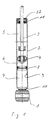
- Hydraulic vibration dampers are used in cooperation with springs resilient and damping suspension of the wheels in relation to the vehicle Motor vehicles used. Your connection to the wheel suspension and vehicle body takes place via stop parts 1.
- stop part 1 which is attached to the end of the outer cylinder 2, shown.
- a Another stop part is usually provided at the end of the piston rod 3.
- a damper piston 4 attached at the end of the piston rod 3.
- This damper piston 4 separates the damping fluid filled interior of the outer cylinder 2 in two work rooms 5, 6. Suitable, Valves, not shown, on the damper piston 4 cause the damping of the oscillating movement of the damper piston connected to the piston rod 3 4.
- a compensation chamber for single-tube vibration dampers 7 provided which is filled with gas.
- This gas-filled compensation chamber 7 is opposite the working rooms 5 and 6 filled with damping fluid via a axially displaceable separating piston 8 separated.
- the separating piston 8 is on his Outer periphery formed with a radial seal that seals against the Inner jacket 9 of the outer cylinder 2 causes.
- the outer cylinder 2 is formed with a bottom 10 and an open end.
- the stop part 1 connects to the bottom 10 of the outer cylinder 2.
- the piston rod 3 which on its immersed end carries the damper piston 4.
- a seal and guide package 11 serves for the radial sliding guiding of the piston rod 3 and Sealing of the working space 5 filled with damping fluid to the outside.
- the 11 oscillating piston rod 3 must be sufficiently lubricated, but one if possible little loss of working fluid should be provided to the outside to achieve a long service life for the vibration damper.
- FIG. 2 shows an enlarged illustration of the area of the sealing and guiding package 11 on the vibration damper.
- the representation is chosen so that the Seal and guide package 11 not yet its during assembly has taken the final assembly position.
- the seal and guide package 11 is in the axial direction with respect to the outer cylinder 2 via two spring washers 12, 13 held in two in the inner jacket 9 of the outer cylinder 2 Grooves 14, 15 engage and the outer jacket 16 of the seal and guide package 11 reach over inside.
- the spring washers 12, 13 have a circumference Separation point so that they can be pushed together radially inwards and have a circular cross-section opposite the seal and Guide package 11 in the inner jacket 9 of the outer cylinder 2 groove 15 for receiving the inner spring ring 13 is introduced approximately semicircular.
- the groove 14 to accommodate the outer spring ring 12 is designed so that it is End 17 of the outer cylinder 2 also circular according to the shape of the Spring rings 12 is formed, wherein it forms approximately the shape of a quarter circle. In In the axially opposite direction, however, the groove 14 tapers approximately conically towards the inner jacket 9 of the outer cylinder 2. This shape of the outer groove 14 brings significant advantages for the entire assembly of the vibration damper.
- the inner groove 15 can, if it makes sense, be formed with this shape.
- the outer cylinder 2 is completely empty in the mounting device or Assembly machine introduced. All installation parts are in the upper tool 18, which is supported on the end 17 of the outer cylinder 2 in a radially and axially guided manner. A stamp 19 is provided above all of the built-in parts and holds the built-in parts can slide one after the other into the interior of the outer cylinder 2.
- the outer cylinder 2 is filled with gas. After that is done through 8 filling channels opening above the separating piston, the complete filling of the outer cylinder 2 with working fluid.
- the separating piston 8 are already pressed into the outer cylinder 2 by the working fluid. After this the working space is completely filled with working fluid, the stamp pushes 19 the remaining built-in parts still in the upper tool 18 in the Inner jacket 9 of the outer cylinder 2, the function of the Damper piston 4 is introduced first.
- this outer groove 14 Tapering towards the inside like a cone is again the force required to compress it this spring ring 13 not as high as that any bruises and thus destruction of the groove edge, spring washer 13 or groove 14 occur.
- the inner spring ring 13 is again on the inner jacket 9 of the outer cylinder 2.
- the radially preloaded seal 20, to seal the seal and guide package against the inner jacket 9 of the outer cylinder 2 is used, due to the shape of the outer groove 14 considerably protected when inserted. The danger of destroying this seal 20 is also minimized by the shape of the groove 14.
- the two snap At the end of the assembly process, the two snap at this point in time lying axially in front of the outer ring surfaces of the seal and guide package 11 Spring washers 12, 13 into the associated grooves 14, 15 approximately simultaneously. From therefore, the two grooves 14, 15 must be spaced from each other at least the height of the seal and guide package 11 plus the thickness of one corresponds to the spring washers 14 or 15.
- This intervention of the recess 21 in the outer spring ring 12 takes place in that by the from the internal pressure built up by the gas, the seal and guide package 11 so far is pushed outward until it radially counteracts with its recess 21 supports the spring ring 12, the recess 21 then extending into the spring ring 12 extends.
- a loosening of the spring ring connection can then only by a Inserting the seal and guide package 11 into the outer cylinder 2, only by applying an external force in this area.
- the open end 17 of the outer cylinder 2 are closed by a sealing cap 22.
- the formation of the fixation of the seal and guide package 11 on the outer cylinder 2 can also be used in a corresponding manner for two-tube vibration dampers become.
- the order of insertion of the built-in parts can also be different Be carried out as described above, especially with regard to the order the operations related to filling with gas and / or working fluid.
- Farther is the subject of the invention and the described method of assembly Also suitable for vibration dampers where the sealing and Guide package 11 only axially via a spring ring 12 lying in a groove 14 supported on the outside.
Abstract
Description
Die Erfindung betrifft einen hydraulischen Schwingungsdämpfer nach dem Oberbegriff des Anspruchs 1.The invention relates to a hydraulic vibration damper according to the preamble of claim 1.
Bei hydraulischen Schwingungsdämpfern, seien es Einrohr- oder Zweirohr-Schwingungsdämpfer, ist es erforderlich, neben dem Einbau der Einbauteile die Schwingungsdämpfer auch mit Dämpfungsflüssigkeit zu füllen sowie bei Einrohr-Schwingungsdämpfern jenseits des Trennkolbens einen Ausgleichsraum mit Gas zu füllen. Weiterhin muß austrittsseitig an einem Ende die oszillierende Kolbenstange abgedichtet und geführt werden. Von daher ist hier ein geeignetes Dichtungs- und Führungspaket einzusetzen.In the case of hydraulic vibration dampers, be it single-tube or two-tube vibration dampers, it is necessary, in addition to the installation of the built-in parts, the vibration damper also to be filled with damping fluid and with single-tube vibration dampers to fill an equalization chamber with gas beyond the separating piston. Furthermore, the oscillating piston rod must be sealed on the outlet side at one end and be led. So here is a suitable seal and guide package to use.
Die DE-PS 1 057 403 befaßt sich ausführlich mit den vorher beschriebenen Problemen. Hier wird, wie beim Erfindungsgegenstand, das Dichtungs- und Führungspaket mittels zweier Federringe, die in Nuten des Außenzylinders eingreifen, axial gehalten. Eine andere Art der Ausbildung des Dichtungs- und Führungspakets ist aus "Reimpell, Stoll, Fahrwerktechnik: Stoß- und Schwingungsdämpfer, Vogel Buchverlag Würzburg 1989" bekannt. Bild 2.22, Seite 43, zeigt ein Dichtungs- und Führungspaket, das sich ebenfalls durch zwei in den Außenzylinder eingreifende Federringe axial abstützt. Eine in eine Nut des Dichtungs- und Führungspakets eingelegte, radial vorgespannte Dichtung übernimmt die radiale Abdichtung zwischen Dichtungs- und Führungspaket und Außenzylinder. Insbesondere die Montage von Einrohr-Schwingungsdämpfern, bei denen ein mit Gas gefüllter, gegenüber dem übrigen Innenvolumen abgetrennter Ausgleichsraum vorgesehen werden muß, gestaltet sich sehr aufwendig. Zur Montage und zum Füllen mit Gas und Dämpfungsflüssigkeit sind mehrere Montage- und Füllstationen erforderlich.DE-PS 1 057 403 deals in detail with the problems described above. Here, as with the subject of the invention, the sealing and guide package held axially by means of two spring washers which engage in grooves in the outer cylinder. Another type of formation of the seal and guide package is from "Reimpell, Stoll, chassis technology: shock and vibration dampers, Vogel Buchverlag Würzburg 1989 ". Figure 2.22, page 43, shows a seal and guide package, that also by two spring rings that engage in the outer cylinder axially supported. An inserted in a groove of the seal and guide package Radially preloaded seal takes over the radial sealing between Seal and guide package and outer cylinder. In particular the assembly of Single-tube vibration dampers, where one is filled with gas, compared to the rest Internal volume separated compensation space must be provided, designed itself very expensive. For assembly and filling with gas and damping fluid several assembly and filling stations are required.
Der Erfindung liegt die Aufgabe zugrunde, gattungsgemäße hydraulische Schwingungsdämpfer
derartig zu gestalten, daß die Montage sich wesentlich vereinfacht
und ein Verfahren zum Zusammenbau eines derartigen Schwingungsdämpfers zu
finden, das die vorstehenden Bedingungen erfüllt. Diese Aufgabe wird erfindungsgemäß
durch einen hydraulischen Schwingungsdämpfer mit den Merkmalen des
Anspruchs 1 gelöst. Vorteilhafte Aus- und Weiterbildungen sind in den Ansprüchen
2 bis 6 beschrieben. Anspruch 7 beschreibt ein erfindungsgemäßes Verfahren zum
Zusammenbau eines gattungsgemäßen Schwingungsdämpfers und Anspruch 8 beschreibt
ein vorteilhaftes Verfahren.The invention has for its object generic hydraulic vibration damper
to be designed in such a way that the assembly is considerably simplified
and a method of assembling such a vibration damper
find that meets the above conditions. This object is achieved according to the invention
by a hydraulic vibration damper with the characteristics of
Claim 1 solved. Advantageous training and further training are in the
Die mit der Erfindung erzielten Vorteile bestehen insbesondere darin, daß für den Einbau sämtlicher beweglicher und abdichtender Einbauteile sowie auch für das Befüllen mit Dämpfungsflüssigkeit und alternativ mit Gas nur eine Arbeitsstation an einer kombinierten Arbeits- und Füllmaschine erforderlich ist. Darüber hinaus wird die Gefahr der Zerstörung von Einbauteilen während der Montage wesentlich reduziert.The advantages achieved by the invention are in particular that for Installation of all movable and sealing installation parts as well as for that Fill with damping fluid and alternatively with gas only at one work station a combined work and filling machine is required. Beyond that the risk of destroying built-in parts during assembly is significantly reduced.
Ein Ausführungsbeispiel der Erfindung ist in der Zeichnung dargestellt und wird im folgenden näher beschrieben. Es zeigen
- Fig. 1
- einen Schnitt durch einen Einrohr-Schwingungsdämpfer und
- Fig. 2
- eine vergrößerte Darstellung des Schwingungsdämpfers im Bereich des Dichtungs- und Führungspakets.
- Fig. 1
- a section through a single-tube vibration damper and
- Fig. 2
- an enlarged view of the vibration damper in the area of the seal and guide package.
Hydraulische Schwingungsdämpfer werden zusammenwirkend mit Federn zur
federnden und dämpfenden Aufhängung der Räder gegenüber dem Fahrzeug bei
Kraftfahrzeugen eingesetzt. Ihre Anbindung an der Radaufhängung und am Fahrzeugaufbau
erfolgt über Anschlagteile 1. Im Ausführungsbeispiel ist nur das Anschlagteil
1, das am Ende des Außenzylinders 2 angebracht ist, dargestellt. Ein
weiteres Anschlagteil ist üblicherweise am Ende der Kolbenstange 3 vorgesehen.
Am in den Außenzylinder 2 eintauchenden Ende der Kolbenstange 3 ist ein Dämpferkolben
4 befestigt. Dieser Dämpferkolben 4 trennt den mit Dämpfungsflüssigkeit
gefüllten Innenraum des Außenzylinders 2 in zwei Arbeitsräume 5, 6. Geeignete,
nicht näher dargestellte Ventile am Dämpferkolben 4 bewirken die Dämpfung der
oszillierenden Bewegung des an der Kolbenstange 3 angebundenen Dämpferkolbens
4. Zum Ausgleich des Verdrängungsvolumens der mehr oder minder eintauchenden
Kolbenstange 3 ist bei Einrohr-Schwingungsdämpfern ein Ausgleichsraum
7 vorgesehen, der mit Gas gefüllt ist. Dieser gasgefüllte Ausgleichsraum 7 wird gegenüber
den mit Dämpfungsflüssigkeit gefüllten Arbeitsräumen 5 und 6 über einen
axial verschieblichen Trennkolben 8 abgetrennt. Der Trennkolben 8 ist an seinem
Außenumfang mit einer Radialdichtung ausgebildet, die die Abdichtung gegen den
Innenmantel 9 des Außenzylinders 2 bewirkt.Hydraulic vibration dampers are used in cooperation with springs
resilient and damping suspension of the wheels in relation to the vehicle
Motor vehicles used. Your connection to the wheel suspension and vehicle body
takes place via stop parts 1. In the exemplary embodiment, only the stop part is
1, which is attached to the end of the
Der Außenzylinder 2 ist mit einem Boden 10 und einem offenen Ende ausgebildet.
An den Boden 10 des Außenzylinders 2 schließt sich das Anschlagteil 1 an. In die
Öffnung des Außenzylinders 2 taucht oszillierend die Kolbenstange 3 ein, die an
ihrem eintauchenden Ende den Dämpferkolben 4 trägt. Ein Dichtungs- und Führungspaket
11 dient zum radialen gleitenden Führen der Kolbenstange 3 und zum
Abdichten des mit Dämpfungsflüssigkeit gefüllten Arbeitsraums 5 nach außen. Dabei
ist zu berücksichtigen, daß die gegenüber dem Dichtungs- und Führungspaket 11
oszillierende Kolbenstange 3 ausreichend geschmiert werden muß, aber ein möglichst
geringer Verlust an Arbeitsflüssigkeit nach außen vorgesehen sein soll, um
eine lange Lebensdauer für den Schwingungsdämpfer zu erzielen.The
Fig. 2 zeigt eine vergrößerte Darstellung des Bereichs Dichtungs- und Führungspaket
11 am Schwingungsdämpfer. Dabei ist die Darstellung so gewählt, daß das
Dichtungs- und Führungspaket 11 während des Zusammenbaus noch nicht seine
endgültige Montagelage eingenommen hat. Das Dichtungs- und Führungspaket 11
wird in axialer Richtung gegenüber dem Außenzylinder 2 über zwei Federringe 12,
13 gehalten, die in zwei in den Innenmantel 9 des Außenzylinders 2 eingebrachte
Nuten 14, 15 eingreifen und den Außenmantel 16 des Dichtungs- und Führungspakets
11 nach innen übergreifen. Die Federringe 12, 13 haben am Umfang eine
Trennstelle, damit sie radial nach innen zusammengeschoben werden können und
weisen einen kreisförmigen Querschnitt auf Die gegenüber dem Dichtungs- und
Führungspaket 11 in den Innenmantel 9 des Außenzylinders 2 eingebrachte Nut 15
zur Aufnahme des innenliegenden Federrings 13 ist etwa halbkreisförmig eingebracht.
Bei endgültiger Lage des Federrings 13 liegt dieser somit etwa zur Hälfte
seines Querschnitts in dieser Nut 15 und übergreift den Außenmantel 16 des Dichtungs- und Führungspakets 11 somit etwa zur Hälfte seines Querschnitts. Die Nut 14
zur Aufnahme des außenliegenden Federrings 12 ist so ausgebildet, daß sie zum
Ende 17 des Außenzylinders 2 hin ebenfalls kreisförmig entsprechend der Form des
Federrings 12 ausgebildet ist, wobei sie etwa die Form eines Viertelkreises bildet. In
der axial entgegengesetzten Richtung verjüngt sich die Nut 14 jedoch etwa konusartig
hin zum Innenmantel 9 des Außenzylinders 2. Diese Form der äußeren Nut 14
bringt wesentliche Vorteile für die gesamte Montage des Schwingungsdämpfers.
Auch die innere Nut 15 kann, wenn es sinnvoll ist, mit dieser Form ausgebildet werden.2 shows an enlarged illustration of the area of the sealing and guiding package
11 on the vibration damper. The representation is chosen so that the
Seal and guide package 11 not yet its during assembly
has taken the final assembly position. The seal and guide package 11
is in the axial direction with respect to the
Für die Montage eines Einrohr-Schwingungsdämpfers entsprechend dem Ausführungsbeispiel
wird der Außenzylinder 2 völlig leer in die Montagevorrichtung oder
Montagemaschine eingebracht. Sämtliche Einbauteile liegen im Oberwerkzeug 18,
das sich auf dem Ende 17 des Außenzylinders 2 radial und axial geführt abstützt.
Oberhalb sämtlicher Einbauteile ist ein Stempel 19 vorgesehen, der die Einbauteile
nacheinander in den Innenraum des Außenzylinders 2 schieben kann. Durch nicht
dargestellte Füllkanäle, die im Oberwerkzeug 18 unterhalb des eingelegten Trennkolbens
8 münden, wird eingangs der Außenzylinder 2 mit Gas gefüllt. Danach erfolgt
durch oberhalb des Trennkolbens 8 mündende Füllkanäle die vollständige Füllung
des Außenzylinders 2 mit Arbeitsflüssigkeit. Hierbei kann der Trennkolben 8
bereits durch die Arbeitsflüssigkeit in den Außenzylinder 2 gedrückt werden. Nachdem
der Arbeitsraum vollständig mit Arbeitsflüssigkeit gefüllt ist, schiebt der Stempel
19 die übrigen sich noch im Oberwerkzeug 18 befindlichen Einbauteile in den
Innenmantel 9 des Außenzylinders 2, wobei entsprechend seiner Funktion der
Dämpferkolben 4 als erstes eingebracht ist.For the assembly of a single-tube vibration damper according to the embodiment
the
Wie aus Fig. 2 ersichtlich, liegt unterhalb des Dichtungs- und Führungspakets 11 ein
Federring 13, der nach dem Dämpferkolben 4 als nächstes in den Innenmantel 9 des
Außenzylinders 2 gelangt. Zum besseren Einführen speziell der Federringe 12, 13
ist das Ende 17 des Außenzylinders 2 an der Innenseite leicht konisch ausgebildet.
Dadurch werden die Kräfte zum Zusammendrücken der Federringe 12,13 nicht unnötig
hoch und auch ein Verquetschen sowohl des Endes 17 des Außenzylinders 2
als auch der Federringe 12, 13 wird vermieden. Die Federringe 12, 13 werden gemeinsam
mit dem Dichtungs- und Führungspaket 11 eingedrückt. Von daher wird
der innere Federring 13 mittels der Unterkante des Dichtungs- und Führungspakets
11 geschoben. Nachdem der innere Federring 13 in den Bereich der äußeren Nut 14
kommt, schnappt er nach außen. Da sich jedoch die Form dieser äußeren Nut 14
nach innen hin konusartig verjüngt, ist wiederum die erforderliche Kraft zum Zusammendrücken
dieses Federrings 13 nicht so hoch, als daß irgendwelche Quetschungen
und damit Zerstörungen von Nutkante, Federring 13 oder Nut 14 eintreten. Beim
weiteren Einschieben der Bauteile liegt dann der innere Federring 13 wieder am Innenmantel
9 des Außenzylinders 2 an. Auch die radial vorgespannte Dichtung 20,
die zum Abdichten des Dichtungs- und Führungspakets gegenüber dem Innenmantel
9 des Außenzylinders 2 eingesetzt wird, wird aufgrund der Form der äußeren Nut
14 beim Einsetzen wesentlich geschont. Die Gefahr einer Zerstörung dieser Dichtung
20 ist ebenfalls durch die Form der Nut 14 minimiert.As can be seen from FIG. 2, lies below the seal and guide package 11
Am Ende des Montagevorganges schnappen die beiden zu diesem Zeitpunkt jeweils
axial vor den äußeren Ringflächen des Dichtungs- und Führungspakets 11 liegenden
Federringe 12, 13 etwa gleichzeitig in die zugehörigen Nuten 14, 15 ein. Von
daher müssen die beiden Nuten 14, 15 einen Abstand voneinander aufweisen, der
wenigstens der Höhe des Dichtungs- und Führungspakets 11 plus der Dicke eines
der Federringe 14 oder 15 entspricht.At the end of the assembly process, the two snap at this point in time
lying axially in front of the outer ring surfaces of the seal and guide package 11
Um eine endgültige Sicherung des äußeren Federrings 12 zu erzielen, ist das
äußere Ende des Dichtungs- und Führungspakets 11 mit einem radialen Rücksprung
21 ausgebildet, der etwa die halbe Dicke des äußeren Federrings 12 aufweist,
so daß der äußere Federring 12, wenn er in der zugehörigen Nut 14 liegt, in
den freien Durchmesser dieses Federrings 12 eingreifen kann. Dieses Eingreifen
des Rücksprungs 21 in den äußeren Federring 12 erfolgt dadurch, daß durch den
vom Gas aufgebauten Innendruck das Dichtungs- und Führungspaket 11 so weit
nach außen geschoben wird, bis es sich mit seinem Rücksprung 21 radial gegen
den Federring 12 abstützt, wobei der Rücksprung 21 sich dann bis in den Federring
12 erstreckt. Ein Lösen der Federringverbindung kann dann nur wieder durch ein
Einschieben des Dichtungs- und Führungspakets 11 in den Außenzylinder 2 erfolgen,
also nur durch Aufbringung einer äußeren Kraft in diesem Bereich. Um die Verschmutzungs- und Verletzungsgefahr zu reduzieren, kann, wie in Fig. 1 gezeigt, das
offene Ende 17 des Außenzylinders 2 durch eine Dichtkappe 22 verschlossen werden.In order to achieve a final securing of the
Die Ausbildung der Fixierung des Dichtungs- und Führungspakets 11 am Außenzylinder
2 kann in entsprechender Weise auch für Zweirohr-Schwingungsdämpfer verwendet
werden. Die Reihenfolge des Einführens der Einbauteile kann auch in anderer
Weise wie vorbeschrieben erfolgen, insbesondere hinsichtlich der Reihenfolge
der Arbeitsgänge bezüglich des Befüllens mit Gas und/oder Arbeitsflüssigkeit. Weiterhin
ist der Erfindungsgegenstand und das beschriebene Verfahren zum Zusammenbau
auch für Schwingungsdämpfer geeignet, bei denen sich das Dichtungs- und
Führungspaket 11 nur über einen in einer Nut 14 liegenden Federring 12 axial nach
außen abstützt. The formation of the fixation of the seal and guide package 11 on the
- 1.1.
- AnschlagteilStop part
- 2.2nd
- AußenzylinderOuter cylinder
- 3.3rd
- KolbenstangePiston rod
- 4.4th
- DämpferkolbenDamper piston
- 5.5.
- Arbeitsraumworking space
- 6.6.
- Arbeitsraumworking space
- 7.7.
- AusgleichsraumCompensation room
- 8.8th.
- TrennkolbenSeparating piston
- 9.9.
- InnenmantelInner jacket
- 10.10th
- Bodenground
- 11.11.
- Dichtungs- und FührungspaketSeal and guide package
- 12.12th
- FederringSpring washer
- 13.13.
- FederringSpring washer
- 14.14.
- NutGroove
- 15.15.
- NutGroove
- 16.16.
- AußenmantelOuter jacket
- 17.17th
- EndeThe End
- 18.18th
- OberwerkzeugUpper tool
- 19.19th
- Stempelstamp
- 20.20th
- Dichtungpoetry
- 21.21.
- RücksprungReturn
- 22.22.
- DichtkappeSealing cap
Claims (8)
Applications Claiming Priority (2)
| Application Number | Priority Date | Filing Date | Title |
|---|---|---|---|
| DE1998123024 DE19823024C2 (en) | 1998-05-22 | 1998-05-22 | Hydraulic vibration damper and method for assembling such a vibration damper |
| DE19823024 | 1998-05-22 |
Publications (2)
| Publication Number | Publication Date |
|---|---|
| EP0959264A2 true EP0959264A2 (en) | 1999-11-24 |
| EP0959264A3 EP0959264A3 (en) | 2002-10-02 |
Family
ID=7868672
Family Applications (1)
| Application Number | Title | Priority Date | Filing Date |
|---|---|---|---|
| EP99105803A Withdrawn EP0959264A3 (en) | 1998-05-22 | 1999-03-23 | Hydraulic damper and assembly method therefor |
Country Status (2)
| Country | Link |
|---|---|
| EP (1) | EP0959264A3 (en) |
| DE (1) | DE19823024C2 (en) |
Cited By (3)
| Publication number | Priority date | Publication date | Assignee | Title |
|---|---|---|---|---|
| WO2007025652A1 (en) * | 2005-08-31 | 2007-03-08 | Zf Friedrichshafen Ag | Piston rod guide, in particular for a single-tube vibration damper |
| EP2107031A1 (en) * | 2008-03-31 | 2009-10-07 | ThyssenKrupp Elevator AG | Hydropneumatic shock absorber for guiding elevator rollers |
| DE102008041995A1 (en) * | 2008-09-11 | 2009-12-10 | Zf Friedrichshafen Ag | Vibration damper i.e. single-tube vibration damper, for use in vehicle, has outlet formed by open annular gap between shell of piston rod guide and inner wall of cylinder, and closing part arranged in gap |
Families Citing this family (3)
| Publication number | Priority date | Publication date | Assignee | Title |
|---|---|---|---|---|
| DE10015911B4 (en) * | 2000-03-30 | 2006-06-29 | Zf Sachs Ag | Axial securing of two components with a retaining ring |
| DE20319511U1 (en) * | 2003-12-16 | 2005-04-28 | Al-Ko Kober Ag | Shock absorber with stop |
| DE102017112998A1 (en) | 2017-06-13 | 2018-12-13 | Thyssenkrupp Ag | vibration |
Citations (1)
| Publication number | Priority date | Publication date | Assignee | Title |
|---|---|---|---|---|
| DE1057403B (en) | 1954-01-23 | 1959-05-14 | Marie Lucien Louis B Christian | End cover for cylinders, especially of hydraulic shock absorbers, with tight piston rod feedthrough |
Family Cites Families (3)
| Publication number | Priority date | Publication date | Assignee | Title |
|---|---|---|---|---|
| DE3611011A1 (en) * | 1986-04-02 | 1987-10-08 | Profil Verbindungstechnik Gmbh | CYLINDER PISTON UNIT FILLED WITH COMPRESSIBLE PRESSURE MEDIUM |
| DE4436967C2 (en) * | 1994-10-15 | 2000-04-20 | Krupp Bilstein Gmbh | Shock absorber lock |
| DE19608771A1 (en) * | 1996-03-07 | 1997-04-24 | Fichtel & Sachs Ag | Guide for piston and cylinder unit, especially for shock absorbers |
-
1998
- 1998-05-22 DE DE1998123024 patent/DE19823024C2/en not_active Expired - Lifetime
-
1999
- 1999-03-23 EP EP99105803A patent/EP0959264A3/en not_active Withdrawn
Patent Citations (1)
| Publication number | Priority date | Publication date | Assignee | Title |
|---|---|---|---|---|
| DE1057403B (en) | 1954-01-23 | 1959-05-14 | Marie Lucien Louis B Christian | End cover for cylinders, especially of hydraulic shock absorbers, with tight piston rod feedthrough |
Non-Patent Citations (1)
| Title |
|---|
| REIMPELL + STOLL: "Stoss- und Schwingungsdämpfer", FAHRWERKTECHNIK (VOGEL BUCHVERLAG), WÜRZBURG 1989 BILD 2.22, pages 43 |
Cited By (4)
| Publication number | Priority date | Publication date | Assignee | Title |
|---|---|---|---|---|
| WO2007025652A1 (en) * | 2005-08-31 | 2007-03-08 | Zf Friedrichshafen Ag | Piston rod guide, in particular for a single-tube vibration damper |
| US7832530B2 (en) | 2005-08-31 | 2010-11-16 | Zf Friedrichshafen Ag | Piston rod guide, in particular for a single-tube vibration damper |
| EP2107031A1 (en) * | 2008-03-31 | 2009-10-07 | ThyssenKrupp Elevator AG | Hydropneumatic shock absorber for guiding elevator rollers |
| DE102008041995A1 (en) * | 2008-09-11 | 2009-12-10 | Zf Friedrichshafen Ag | Vibration damper i.e. single-tube vibration damper, for use in vehicle, has outlet formed by open annular gap between shell of piston rod guide and inner wall of cylinder, and closing part arranged in gap |
Also Published As
| Publication number | Publication date |
|---|---|
| DE19823024C2 (en) | 2001-11-15 |
| EP0959264A3 (en) | 2002-10-02 |
| DE19823024A1 (en) | 2000-03-23 |
Similar Documents
| Publication | Publication Date | Title |
|---|---|---|
| DE3128723C2 (en) | ||
| DE2922437C2 (en) | ||
| DE2905928C2 (en) | ||
| DE3122626C2 (en) | ||
| DE2813992C3 (en) | Double tube type hydraulic shock absorber | |
| DE3206124A1 (en) | HYDROPNEUMATIC TWO-TUBE VIBRATION DAMPER WITH AN OIL SCRAPER ARRANGED IN THE AREA OF A PISTON ROD GUIDE | |
| DE3623787A1 (en) | GAS SPRING WITH LIMIT DAMPING | |
| EP0033839A2 (en) | Self-pumping hydropneumatic telescopic spring damping unit with interior level control | |
| EP0687832B1 (en) | Adjustable-length gas spring and adjustable-length column for chairs and tables with a gas spring of adjustable length | |
| DE2320913A1 (en) | HYDRAULIC SHOCK ABSORBER | |
| DE102017008752A1 (en) | Hydraulic damping device | |
| EP1085233A2 (en) | Hydraulic shock absorber for motor vehicles | |
| DE2507308B2 (en) | Housing closure on the piston rod side for a telescopic shock absorber for motor vehicles carrying a wheel axle stub | |
| DE69830692T2 (en) | Hydraulic shock absorber | |
| DE3839446C2 (en) | ||
| EP0959264A2 (en) | Hydraulic damper and assembly method therefor | |
| DE102006011397B3 (en) | Suspension system for motor vehicle, has connection unit that is connected with cladding body, where unit comprises tappet that engages in corresponding recess of shaped disk, and disk firmly covering bore of plunger guide | |
| CH666731A5 (en) | PISTON, ESPECIALLY FOR HYDRAULIC OR PNEUMATIC WORKING CYLINDERS. | |
| DE3445684A1 (en) | Vibration damper for vehicles | |
| DE10047878B4 (en) | Shock absorbers with amplitude-dependent damping | |
| DE4408405B4 (en) | Vibration damper with mechanical cable stop | |
| DE3103794A1 (en) | SHOCK ABSORBER WITH A BUFFER | |
| EP2696096A2 (en) | Separating piston | |
| DE7837029U1 (en) | Shock absorber or strut with mechanical cable stop | |
| EP3317559B1 (en) | Hydraulic vibration damper |
Legal Events
| Date | Code | Title | Description |
|---|---|---|---|
| PUAI | Public reference made under article 153(3) epc to a published international application that has entered the european phase |
Free format text: ORIGINAL CODE: 0009012 |
|
| AK | Designated contracting states |
Kind code of ref document: A2 Designated state(s): AT BE CH CY DE DK ES FI FR GB GR IE IT LI LU MC NL PT SE |
|
| AX | Request for extension of the european patent |
Free format text: AL;LT;LV;MK;RO;SI |
|
| RAP1 | Party data changed (applicant data changed or rights of an application transferred) |
Owner name: THYSSENKRUPP BILSTEIN GMBH |
|
| PUAL | Search report despatched |
Free format text: ORIGINAL CODE: 0009013 |
|
| AK | Designated contracting states |
Kind code of ref document: A3 Designated state(s): AT BE CH CY DE DK ES FI FR GB GR IE IT LI LU MC NL PT SE |
|
| AX | Request for extension of the european patent |
Free format text: AL;LT;LV;MK;RO;SI |
|
| RIC1 | Information provided on ipc code assigned before grant |
Free format text: 7F 16F 9/36 A, 7F 16F 9/32 B |
|
| 17P | Request for examination filed |
Effective date: 20020823 |
|
| AKX | Designation fees paid |
Designated state(s): DE FR GB IT |
|
| 17Q | First examination report despatched |
Effective date: 20030807 |
|
| STAA | Information on the status of an ep patent application or granted ep patent |
Free format text: STATUS: THE APPLICATION HAS BEEN WITHDRAWN |
|
| 18W | Application withdrawn |
Effective date: 20031011 |