EP0959260A2 - Scheibenbremse für ein Landfahrzeug - Google Patents
Scheibenbremse für ein Landfahrzeug Download PDFInfo
- Publication number
- EP0959260A2 EP0959260A2 EP99109958A EP99109958A EP0959260A2 EP 0959260 A2 EP0959260 A2 EP 0959260A2 EP 99109958 A EP99109958 A EP 99109958A EP 99109958 A EP99109958 A EP 99109958A EP 0959260 A2 EP0959260 A2 EP 0959260A2
- Authority
- EP
- European Patent Office
- Prior art keywords
- brake
- disc
- carrier
- pad
- lining
- Prior art date
- Legal status (The legal status is an assumption and is not a legal conclusion. Google has not performed a legal analysis and makes no representation as to the accuracy of the status listed.)
- Withdrawn
Links
Images


Classifications
-
- F—MECHANICAL ENGINEERING; LIGHTING; HEATING; WEAPONS; BLASTING
- F16—ENGINEERING ELEMENTS AND UNITS; GENERAL MEASURES FOR PRODUCING AND MAINTAINING EFFECTIVE FUNCTIONING OF MACHINES OR INSTALLATIONS; THERMAL INSULATION IN GENERAL
- F16D—COUPLINGS FOR TRANSMITTING ROTATION; CLUTCHES; BRAKES
- F16D65/00—Parts or details
- F16D65/02—Braking members; Mounting thereof
- F16D65/04—Bands, shoes or pads; Pivots or supporting members therefor
- F16D65/092—Bands, shoes or pads; Pivots or supporting members therefor for axially-engaging brakes, e.g. disc brakes
-
- F—MECHANICAL ENGINEERING; LIGHTING; HEATING; WEAPONS; BLASTING
- F16—ENGINEERING ELEMENTS AND UNITS; GENERAL MEASURES FOR PRODUCING AND MAINTAINING EFFECTIVE FUNCTIONING OF MACHINES OR INSTALLATIONS; THERMAL INSULATION IN GENERAL
- F16D—COUPLINGS FOR TRANSMITTING ROTATION; CLUTCHES; BRAKES
- F16D55/00—Brakes with substantially-radial braking surfaces pressed together in axial direction, e.g. disc brakes
- F16D55/02—Brakes with substantially-radial braking surfaces pressed together in axial direction, e.g. disc brakes with axially-movable discs or pads pressed against axially-located rotating members
- F16D55/22—Brakes with substantially-radial braking surfaces pressed together in axial direction, e.g. disc brakes with axially-movable discs or pads pressed against axially-located rotating members by clamping an axially-located rotating disc between movable braking members, e.g. movable brake discs or brake pads
- F16D55/224—Brakes with substantially-radial braking surfaces pressed together in axial direction, e.g. disc brakes with axially-movable discs or pads pressed against axially-located rotating members by clamping an axially-located rotating disc between movable braking members, e.g. movable brake discs or brake pads with a common actuating member for the braking members
-
- F—MECHANICAL ENGINEERING; LIGHTING; HEATING; WEAPONS; BLASTING
- F16—ENGINEERING ELEMENTS AND UNITS; GENERAL MEASURES FOR PRODUCING AND MAINTAINING EFFECTIVE FUNCTIONING OF MACHINES OR INSTALLATIONS; THERMAL INSULATION IN GENERAL
- F16D—COUPLINGS FOR TRANSMITTING ROTATION; CLUTCHES; BRAKES
- F16D55/00—Brakes with substantially-radial braking surfaces pressed together in axial direction, e.g. disc brakes
- F16D2055/0004—Parts or details of disc brakes
- F16D2055/0008—Brake supports
-
- F—MECHANICAL ENGINEERING; LIGHTING; HEATING; WEAPONS; BLASTING
- F16—ENGINEERING ELEMENTS AND UNITS; GENERAL MEASURES FOR PRODUCING AND MAINTAINING EFFECTIVE FUNCTIONING OF MACHINES OR INSTALLATIONS; THERMAL INSULATION IN GENERAL
- F16D—COUPLINGS FOR TRANSMITTING ROTATION; CLUTCHES; BRAKES
- F16D55/00—Brakes with substantially-radial braking surfaces pressed together in axial direction, e.g. disc brakes
- F16D2055/0004—Parts or details of disc brakes
- F16D2055/0016—Brake calipers
- F16D2055/002—Brake calipers assembled from a plurality of parts
Definitions
- the invention relates to a disc brake for a land vehicle, with a brake disc, a brake carrier and at least a brake pad carried by a pad carrier, the when the brake is actuated in a predetermined direction the brake disc is pressed.
- Disc brakes of the type mentioned are known for example from EP-PS 641 949. These are in the element referred to as the brake carrier by one Brake force absorbing part of the brake, the guide and is used to support brake shoes. With the conventional The brake shoes are stored in a lining shaft and brake support themselves laterally against the outward ones Arms with guide surfaces. The brake carrier is closed and encompasses the brake disc like a frame. The casting technology Manufacture of such a brake carrier and machining the necessary guide surfaces are complex. Further the known design limits the serviceability of the Brake on because of the frame-like encirclement of the brake disc an exchange of the brake disc only after previous, at least partial disassembly of the brake carrier allowed. By the frame-like brake carrier is between the guide surfaces and the brake disc has a functional clearance, whereby it falls below the wear limit the brake disc and / or the brake pad to fall out a brake shoe can come. This leads to a total failure the brake.
- the invention is therefore based on the object Disc brake with a brake carrier of the aforementioned Art to develop in such a way that with simplified production improved serviceability and high security be achieved.
- the object is achieved in that that the lining carrier is arranged and held in such a way that its distance from in the predetermined direction the center plane of the brake disc in no operating condition Brake falls below a predetermined minimum distance.
- the lining carrier is beyond a predeterminable amount approaches the brake disc. Because this measure should be chosen in this way can that a falling out of neither the brake pad, nor the Brake pad threatens, the risk of total failure of the Reliably relieved of the brake. Still, the brake disc can do a lot can simply be pulled off in the axial direction, which makes it easier to service elevated.
- the brake pad is attached to the pad carrier, the pad carrier for braking in the predetermined direction of the brake carrier is movable and a first stop the brake carrier is provided, the displacement of the lining carrier limited to a given amount.
- the lining carrier is movable held, but can because of the first stop of the brake disc not approach beyond a predetermined amount, so that a falling out of the brake pad with the attached Brake pad is not to be feared.
- a second stop can be provided on the lining carrier be when the specified minimum distance is reached of the brake disc from the center plane of the brake disc on the strikes the first stop provided on the brake carrier.
- the first stop is preferably in the direction of the axis of rotation the brake disc seen outside the circumference of the Brake disc. This configuration is particularly on the reaction side the brake is advantageous because it makes it the first Stop during assembly / disassembly of the brake disc not in the Is gone, but the brake disc can be pulled off unhindered can.
- the first stop on one is preferred seen outside in the direction of the axis of rotation of the brake disc yoke formed the circumferential line of the brake disc.
- the invention is contrary to the embodiment according to EP-PS 641 949 a yoke is provided, which not reaching behind the brake disc, but reaching over it, so that it is not in the way when the brake disc is removed.
- the yoke can also act as a bridge-like connection between an entry point and an exit point of the brake carrier.
- At least one approach is also preferred provided on the lining carrier, which extends in the radial direction the brake disc seen on a guide surface of the brake carrier slidably supported. This prevents the brake pad falls radially inwards into the brake.
- the brake pad for braking in the predetermined Direction is held in the lining carrier and the Pad carrier is releasably attached in the brake carrier.
- the application force acts on the brake pad, but not on it the brake pad.
- the special design of the bracket of the Brake lining in the lining carrier is the subject of a simultaneous deposited registration.
- the brake carrier preferably has seen in the direction of the axis of rotation of the brake disc yoke lying outside the circumference of the brake disc on which the pad carrier is releasably attached. At this Design is therefore a for fastening the brake pad Element used in the assembly / disassembly of the brake disc is not in the way.
- the brake pad can preferably be used for braking slidable in the predetermined direction in the lining carrier be held, the lining carrier as part of the brake carrier is executed. Again, the clamping force applies acts on the brake pad, but not on the pad carrier.
- This configuration has the same advantages as in the design according to which the lining carrier on the brake carrier is releasably attached.
- the brake carrier can be in the direction of the axis of rotation the brake disc seen outside the circumference of the Have brake disc lying yoke that is integral with the Cover carrier is executed.
- the same applies here as well Advantages are to be achieved, as in that embodiment, after which the pad carrier is releasably attached to the yoke.
- the yoke is preferably removable from the remaining parts of the brake carrier attached. This has the advantage that only the corresponding attachment has to be loosened, around the yoke with the brake lining held in it by the brake carrier to decrease. This is not just quick access secured to the brake disc. Rather, it is also a quick access to the brake pads realized.
- the yoke-shaped connecting part expediently has a larger width A than the brake disc thickness B. Because the arcuate connecting yoke over the disc diameter D extends, are both the stop and the holding areas for the brake shoes outside the rotational contour of the Brake disc.
- the brake pad is further preferred in a through opening arranged in the lining carrier.
- Words is a completely enclosing the brake pad Provided with an all-round reliable bracket and Guidance of the brake pad ensures.
- the passage opening Allows the brake pad to be inserted away from the disc Page ago.
- the through opening has a circular inner contour and the brake pad in Cross-section has a circular outer contour. This will make the Assembly / disassembly of the brake pad on the pad carrier especially simple.
- the covering carrier can be used to carry two or more brake pads. This can cause the friction surface enlarged and therefore very variable according to the respective Use case to be designed. Gaps between neighboring brake pads leave a much better one Air circulation and thus an improved cooling function, causing damage to the brake pad and / or the brake disc can be prevented by overheating due to continuous braking can.
- the brake carrier can be made in one piece with one for receiving trained by braking force serving part of the land vehicle be.
- the disc brake is preferably a Sliding caliper disc brake.
- sliding saddles of the radially open design how they are used in particular in commercial vehicles, a radial depending on the size of the braking force Widening.
- This elastic radial deformation occurs in particular on the reaction side saddle leg in the form of a Inclination on, which leads to the reaction-side Brake pad for a non-uniform contact pressure comes against the brake disc.
- edge pressures occur, radial oblique wear and excessive Brake disc load on, which then leads to heat cracks on the Can lead brake disc.
- This critical and a permanent load area on the sliding saddle subject to deformation the brake disc is always in the transition area from the two overlapping bridge areas in the radially inward running reaction-side caliper leg. Two such Areas are marked in FIG. 10 by dashed frames.
- Another disadvantage of the described embodiment lies in that it is only possible to change the brake disc if previously the brake caliper bolt guides from the brake carrier solved and then the overlapping the brake disc Sliding saddle has been completely removed. The expansion is accordingly cumbersome and time consuming.
- the disc brake has a sliding saddle which consists of at least two parts releasably connected together, wherein to connect the two parts at least one in the transition area between one radially outside the circumference the brake disc lying bridge area and the brake disc radially overlapping reaction caliper legs arranged connecting element, which is in Axial direction of the brake disc extends.
- One of the two parts preferably has the brake disc radially overlapping caliper legs.
- the fasteners for example formed by screws can be from the reaction side (open vehicle side) removed from the caliper leg of the Bridge area can be removed, giving free access is created from this side to the brake disc. So can without dismantling the other saddle parts, for example any Bolt guides, the brake disc below the bridge area to the open side of the vehicle.
- reaction side Brake caliper legs for example, made of one material higher strength, such as as a forged part the remaining saddle parts can be manufactured. This leaves the saddle dimensions have a positive influence.
- the brake caliper leg designed as an extra part, leaves also a much better and more flexible design and processing of the topping structure.
- Fig. 1 shows a perspective side view of a Embodiment of the invention, namely a brake carrier 2, while Fig. 2 shows a sectional side view.
- the area 3 consists of a yoke-shaped Connecting part 6 of greater width A than the brake disc thickness B and from guide surfaces 9 provided on both sides for brake shoes 4, 5.
- the yoke-shaped connecting part runs from an entry point to an exit point of the brake carrier 2. Contact surfaces serve to stop the brake shoes 7, 8 on the connecting part 6.
- the radial bracket and guidance of the brake shoes 4, 5 serve strips 11 on which the brake shoes rest with side projections 10.
- the Actuation is carried out by an application device Z, which in the Figures 5 and 6 is indicated schematically.
- Fig. 3 shows schematically a to be inserted into the brake carrier Brake shoe 4 (5) with the details previously described. There is a fixed connection in this version between the brake pad 12 'and the pad carrier 13'.
- Fig. 4 shows those already in the brake carrier on the last Brake shoes 4, 5. In contrast to the illustration according to FIG. 3 4 put the brake shoes from a lining carrier 13 and brake pads 12 slidably held therein.
- Fig. 5 shows an embodiment in which the leadership of the Brake pads 12 serving lining carrier 13 by means of a screw 14 are attached to the connecting part 6.
- the brake pad 12 On the right side of the brake disc 1, the brake pad 12 is in new condition shown, on the left a worn one Brake pad 12.
- another Cover shifting by the application device Z on the left Side no longer take place. It is therefore impossible that the brake pad 12 pushed too far towards the brake disc 1 is, which is why the brake pad 12 falls out of its Guide / bracket is excluded.
- FIG. 7 is a perspective side view of FIG 6 building brake carrier 2 shown, the upper part, which is composed of the areas 6, 13 with the Lower part of the brake carrier 2 held together by means of screw connections 15 is.
- Fig. 8 shows a sectional side view through level VIII / VIII in the area of the mentioned screw connection 15.
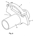
- Fig. 9 shows in perspective the open, the brake disc 1 overlapping side of the brake carrier 2 according to the invention, here as an integrated part of a vehicle part 16.
- the yoke-shaped connecting part 6 the width A with the surfaces 7, 8 the guarantee that a excessive displacement of the brake shoes - no matter what version - in the direction of brake disc 1 only up to a defined one Wear limit is possible.
- the contact between the brake shoes and all guide and stop surfaces of the brake carrier remains intact.
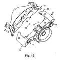
- a sliding caliper 20 is axially displaceable through bolt guides 21 on a brake carrier 22 (not shown) mounted and encompasses a brake disc 23 his two saddle legs.
- the bolt guides are located in the actuating side saddle leg 24, which is an actuating device having. Extend from this saddle leg over the outer circumference of the brake disc two Bridge struts 25, at the ends of which there is a reaction side Saddle leg 26 connects.
- actuating side saddle leg 24 Extend from this saddle leg over the outer circumference of the brake disc two Bridge struts 25, at the ends of which there is a reaction side Saddle leg 26 connects.
- connection profiles e.g. Claw profiles etc.
- connection profiles e.g. Claw profiles etc.
- reaction side Saddle leg 26 made of a material of higher strength, e.g. as a forged part compared to the other saddle parts 24, 25 can be produced. This allows the Saddle saddle influence positively.
- the saddle leg is available as an extra part 26 also a much better and more flexible design and machining of a lining system structure 32.
Landscapes
- Engineering & Computer Science (AREA)
- General Engineering & Computer Science (AREA)
- Mechanical Engineering (AREA)
- Braking Arrangements (AREA)
Abstract
Description
Claims (20)
- Scheibenbremse für ein Landfahrzeug, miteiner Bremsscheibe (1),einem Bremsenträger (2) undmindestens einem von einem Belagträger (13) getragenen Bremsbelag (12), der bei Betätigen der Bremse in einer vorbestimmten Richtung gegen die Bremsscheibe (1) gedrückt wird,
dadurch gekennzeichnet, daßder Belagträger (13) derart angeordnet und gehalten ist, daß sein in der vorbestimmten Richtung gesehener Abstand von der Mittelebene (E) der Bremsscheibe (1) in keinem Betriebszustand der Bremse einen vorgegebenen Mindestabstand unterschreitet. - Scheibenbremse nach Anspruch 1, dadurch gekennzeichnet, daß der Bremsbelag (12') an dem Belagträger (13') befestigt ist, der Belagträger zum Bremsen in der vorbestimmten Richtung bezüglich des Bremsenträgers (2) verschieblich ist und ein erster Anschlag (7) an dem Bremsenträger (2) vorgesehen ist, der die Verschiebung des Belagträgers auf ein vorgegebenes Maß begrenzt.
- Scheibenbremse nach Anspruch 2, gekennzeichnet durch einen an dem Belagträger vorgesehenen zweiten Anschlag, der bei Erreichen des vorgegebenen Mindestabstands des Belagträgers von der Mittelebene (E) der Bremsscheibe (1) an dem an dem Bremsenträger (2) vorgesehenen ersten Anschlag (7) anschlägt.
- Scheibenbremse nach Anspruch 2 oder 3, dadurch gekennzeichnet, daß der erste Anschlag (7) in Richtung der Drehachse der Bremsscheibe (1) gesehen außerhalb der Umfangslinie (D) der Bremsscheibe (1) liegt.
- Scheibenbremse nach einem der Ansprüche 2 bis 4, dadurch gekennzeichnet, daß der erste Anschlag (7) an einem in Richtung der Drehachse der Bremsscheibe (1) gesehen außerhalb der Umfangslinie (D) der Bremsscheibe (1) liegenden Joch (6) ausgebildet ist.
- Scheibenbremse nach einem der Ansprüche 2 bis 5, gekennzeichnet durch Führungsflächen (9, 11) zum verschieblichen Halten des Belagträgers an dem Bremsenträger (2) in Richtung der Drehachse der Bremsscheibe (1) gesehen und zum Einleiten der auf den Bremsbelag (12) wirkenden Reibkräfte in den Bremsenträger (2) außerhalb der Umfangslinie (D) der Bremsscheibe (1) liegen.
- Scheibenbremse nach einem der Ansprüche 2 bis 6, gekennzeichnet durch mindestens einen Ansatz (10) an dem Belagträger, der sich in Radialrichtung der Bremsscheibe (1) gesehen an einer Führungsfläche (11) des Bremsenträgers (2) verschieblich abstützt.
- Scheibenbremse nach Anspruch 1, dadurch gekennzeichnet, daß der Bremsbelag (12) zum Bremsen in der vorbestimmten Richtung verschieblich in dem Belagträger (13) gehalten ist und der Belagträger (13) an dem Bremsenträger (2) lösbar befestigt ist.
- Scheibenbremse nach Anspruch 8, dadurch gekennzeichnet, daß der Bremsenträger (2) ein in Richtung der Drehachse der Bremsscheibe (1) gesehen außerhalb der Umfangslinie (D) der Bremsscheibe (1) liegendes Joch (6) aufweist, an dem der Belagträger (13) lösbar befestigt ist.
- Scheibenbremse nach Anspruch 1, dadurch gekennzeichnet, daß der Bremsbelag (12) zum Bremsen in der vorbestimmten Richtung verschieblich an dem Belagträger (13) gehalten ist und der Belagträger (13) als Teil des Bremsenträgers (2) ausgeführt ist.
- Scheibenbremse nach Anspruch 10, dadurch gekennzeichnet, daß der Bremsenträger (2) ein in Richtung der Drehachse der Bremsscheibe (1) gesehen außerhalb der Umfangslinie der Bremsscheibe (1) liegendes Joch (6) aufweist, das einstückig mit dem Belagträger (13) ausgeführt ist.
- Scheibenbremse nach Anspruch 11, dadurch gekennzeichnet, daß das Joch (6) abnehmbar an den übrigen Teilen des Bremsenträgers (2) befestigt ist.
- Scheibenbremse nach einem der Ansprüche 1 bis 12, dadurch gekennzeichnet, daß das jochförmige Verbindungsteil (6) eine größere Breite A als die Bremsscheibendicke B aufweist.
- Scheibenbremse nach einem der Ansprüche 8 bis 13, dadurch gekennzeichnet, daß der Bremsbelag (12) in einer Durchgangsöffnung in dem Belagträger (13) angeordnet ist.
- Scheibenbremse nach Anspruch 14, dadurch gekennzeichnet, daß die Durchgangsöffnung eine kreisförmige Innenkontur hat und der Bremsbelag (12) eine im Querschnitt kreisförmige Außenkontur hat.
- Scheibenbremse nach einem der vorangehenden Ansprüche, dadurch gekennzeichnet, daß der Belagträger (13) zum Tragen von zwei oder mehr Bremsbelägen (12) ausgelegt ist.
- Scheibenbremse nach einem der vorangehenden Ansprüche, dadurch gekennzeichnet, daß der Bremsenträger (2) einstückig mit einem zum Aufnehmen von Bremskräften dienenden Teil (16) des Landfahrzeugs ausgebildet ist.
- Scheibenbremse nach einem der vorangehenden Ansprüche, dadurch gekennzeichnet, daß sie eine Gleitsattelscheibenbremse ist.
- Scheibenbremse nach Anspruch 18, dadurch gekennzeichnet, daß sie einen Gleitsattel (20) aufweist, der sich aus mindestens zwei lösbar miteinander verbundenen Teilen (25, 26) zusammensetzt, wobei zur Verbindung der beiden Teile (25, 26) mindestens ein im Übergangsbereich zwischen einem radial außerhalb der Umfangslinie (D) der Bremsscheibe (23) liegenden Brückenbereich und einem die Bremsscheibe (23) radial überlappenden reaktionsseitigen Bremssattelschenkel angeordnetes Verbindungselement (29) dient, das sich in Axialrichtung der Bremsscheibe (23) erstreckt.
- Scheibenbremse nach Anspruch 19, dadurch gekennzeichnet, daß eines der beiden Teile (25, 26) den die Bremsscheibe (23) radial überlappenden Bremssattelschenkel aufweist.
Applications Claiming Priority (2)
| Application Number | Priority Date | Filing Date | Title |
|---|---|---|---|
| DE19823034 | 1998-05-22 | ||
| DE1998123034 DE19823034C1 (de) | 1998-05-22 | 1998-05-22 | Scheibenbremse für ein Landfahrzeug |
Publications (2)
| Publication Number | Publication Date |
|---|---|
| EP0959260A2 true EP0959260A2 (de) | 1999-11-24 |
| EP0959260A3 EP0959260A3 (de) | 2001-06-06 |
Family
ID=7868675
Family Applications (1)
| Application Number | Title | Priority Date | Filing Date |
|---|---|---|---|
| EP99109958A Withdrawn EP0959260A3 (de) | 1998-05-22 | 1999-05-20 | Scheibenbremse für ein Landfahrzeug |
Country Status (2)
| Country | Link |
|---|---|
| EP (1) | EP0959260A3 (de) |
| DE (1) | DE19823034C1 (de) |
Cited By (2)
| Publication number | Priority date | Publication date | Assignee | Title |
|---|---|---|---|---|
| WO2007051616A1 (de) * | 2005-11-03 | 2007-05-10 | Knorr-Bremse Systeme für Nutzfahrzeuge GmbH | Scheibenbremse, insbesondere für ein nutzfahrzeug, sowie bremsbelag für eine scheibenbremse |
| JP2008075874A (ja) * | 2006-09-19 | 2008-04-03 | Meritor Heavy Vehicle Braking Systems (Uk) Ltd | ブレーキキャリア |
Families Citing this family (4)
| Publication number | Priority date | Publication date | Assignee | Title |
|---|---|---|---|---|
| DE10018523B4 (de) * | 2000-04-13 | 2005-03-31 | Knorr-Bremse Systeme für Nutzfahrzeuge GmbH | Scheibenbremse mit einer Bremsbelaghalterung |
| DE102004045218B4 (de) * | 2004-09-17 | 2014-06-18 | Wabco Radbremsen Gmbh | Bremsenträger und scheibenbremse mit einem solchen bremsenträger |
| DE102012006092A1 (de) * | 2012-03-26 | 2013-09-26 | Knorr-Bremse Systeme für Nutzfahrzeuge GmbH | Scheibenbremse und Bremsbelag |
| DE102024114116A1 (de) * | 2024-05-21 | 2025-12-18 | Zf Cv Systems Europe Bv | Zentrierungsvorrichtung für eine Scheibenbremse für ein Fahrzeug, insbesondere Nutzfahrzeug, Träger mit Zentrierungsvorrichtung, Scheibenbremse, Fahrzeug |
Family Cites Families (11)
| Publication number | Priority date | Publication date | Assignee | Title |
|---|---|---|---|---|
| DE1887149U (de) * | 1964-02-06 | Alfred Teves Maschinen- und Armaturenfabrik K.G., Frankfurt/M | Teilbelagscheibenbremse | |
| FR1383346A (fr) * | 1963-02-27 | 1964-12-24 | Ernst Heinkel A G | Frein hydraulique à disque |
| DE1966690C3 (de) * | 1968-10-02 | 1980-09-18 | Girling Ltd., Birmingham, West Midlands (Ver. Koenigreich) | Sattelführung für eine Schwimmsattel-Teilbelagscheibenbremse für Fahrzeuge |
| DE2408075A1 (de) * | 1974-02-20 | 1975-09-04 | Teves Gmbh Alfred | Scheibenbremse |
| DE2804977C2 (de) * | 1978-02-06 | 1986-07-10 | Alfred Teves Gmbh, 6000 Frankfurt | Schwimmsattelbremse, insbesondere für Kraftfahrzeuge |
| US4341289A (en) * | 1978-09-25 | 1982-07-27 | Lucas Industries Limited | Disc brakes |
| DE4301006C2 (de) * | 1993-01-18 | 1997-06-05 | Becorit Grubenausbau Gmbh | Bremsbelag für Teilbelag- oder Vollbelag-Scheibenbremsen |
| DE9307017U1 (de) * | 1993-05-08 | 1993-07-15 | Jurid Werke Gmbh, 2056 Glinde | Bremsbelag für Scheibenbremsen |
| US5467847A (en) * | 1993-09-02 | 1995-11-21 | Perrot Bremsen Gmbh | Disc brake |
| DE19626297A1 (de) * | 1996-07-01 | 1998-01-08 | Teves Gmbh Alfred | Bremsträger |
| DE19743538A1 (de) * | 1997-10-01 | 1999-04-08 | Wabco Perrot Bremsen Gmbh | Gleitsattel-Scheibenbremse |
-
1998
- 1998-05-22 DE DE1998123034 patent/DE19823034C1/de not_active Expired - Fee Related
-
1999
- 1999-05-20 EP EP99109958A patent/EP0959260A3/de not_active Withdrawn
Cited By (5)
| Publication number | Priority date | Publication date | Assignee | Title |
|---|---|---|---|---|
| WO2007051616A1 (de) * | 2005-11-03 | 2007-05-10 | Knorr-Bremse Systeme für Nutzfahrzeuge GmbH | Scheibenbremse, insbesondere für ein nutzfahrzeug, sowie bremsbelag für eine scheibenbremse |
| JP2008075874A (ja) * | 2006-09-19 | 2008-04-03 | Meritor Heavy Vehicle Braking Systems (Uk) Ltd | ブレーキキャリア |
| EP1903242A3 (de) * | 2006-09-19 | 2009-04-01 | Meritor Heavy Vehicle Braking Systems (UK) Limited | Bremsenträger |
| CN102537147A (zh) * | 2006-09-19 | 2012-07-04 | 英国美瑞特重型车制动系统有限公司 | 制动器挂架 |
| US9222532B2 (en) | 2006-09-19 | 2015-12-29 | Meritor Heavy Vehicle Braking Systems (Uk) Limited | Brake carrier |
Also Published As
| Publication number | Publication date |
|---|---|
| EP0959260A3 (de) | 2001-06-06 |
| DE19823034C1 (de) | 1999-12-02 |
Similar Documents
| Publication | Publication Date | Title |
|---|---|---|
| DE60305886T2 (de) | Verbesserter scheibenbremsensattel | |
| EP0412541B1 (de) | Teilbelag-Scheibenbremse | |
| DE69605862T2 (de) | Scheibenbremse | |
| DE2822379C3 (de) | Bremsscheibe für Scheibenbremsen, insbesondere Fahrzeugbremsen | |
| EP2929208B1 (de) | Scheibenbrems- und niederhaltefeder einer solchen scheibenbremse | |
| DE102018120512B4 (de) | Scheibenbremse für ein Nutzfahrzeug und Bremsbelagsatz | |
| EP2252805B1 (de) | Scheibenbremse mit orientierungsgesichertem einbau der bremsbeläge | |
| EP2570689A1 (de) | Scheibenbremse eines Kraftfahrzeugs und Bremsbelag | |
| DE102012103017A1 (de) | Lagerung eines eine teilzylindrische Außenfläche aufweisenden Drehhebels gegenüber einem Druckstück | |
| WO2014183838A1 (de) | Sattelscheibenbremse eines fahrzeugs, insbesondere eines nutzfahrzeugs, und niederhalteeinrichtung einer solchen bremse | |
| EP1898115A1 (de) | Fahrzeug-Scheibenbremse | |
| DE2113946C3 (de) | Lösbare Verbindung zwischen dem Bremssattel und dem Hydraulikzylinder einer Teilbelag-Scheibenbremse | |
| CH658501A5 (de) | Scheibenbremse. | |
| WO2017036763A1 (de) | Scheibenbremse eines nutzfahrzeugs | |
| DE3839957A1 (de) | Teilbelag-scheibenbremse | |
| EP0959260A2 (de) | Scheibenbremse für ein Landfahrzeug | |
| DE2711728C2 (de) | Bremsscheibe, insbesondere für Schienenfahrzeuge | |
| DE19743538A1 (de) | Gleitsattel-Scheibenbremse | |
| EP0959259A2 (de) | Scheibenbremse für ein Landfahrzeug | |
| DE2818682A1 (de) | Trommelbremse sowie bremsbacke und schwenkzapfen hierfuer | |
| DE4110869A1 (de) | Festsattel-teilbelagscheibenbremse | |
| EP0984188B1 (de) | Teilbelagscheibenbremse | |
| WO1992017713A1 (de) | Festsattel-teilbelagscheibenbremse | |
| DE3036985C2 (de) | ||
| WO2018138203A1 (de) | Bremsbacke, system zum modularen zusammensetzen einer bremsbacke, bremsvorrichtung und verfahren zur herstellung einer bremsbacke |
Legal Events
| Date | Code | Title | Description |
|---|---|---|---|
| PUAI | Public reference made under article 153(3) epc to a published international application that has entered the european phase |
Free format text: ORIGINAL CODE: 0009012 |
|
| AK | Designated contracting states |
Kind code of ref document: A2 Designated state(s): DE FR GB IT SE |
|
| AX | Request for extension of the european patent |
Free format text: AL;LT;LV;MK;RO;SI |
|
| PUAL | Search report despatched |
Free format text: ORIGINAL CODE: 0009013 |
|
| RIC1 | Information provided on ipc code assigned before grant |
Free format text: 7F 16D 65/092 A, 7F 16D 55/226 B |
|
| AK | Designated contracting states |
Kind code of ref document: A3 Designated state(s): AT BE CH CY DE DK ES FI FR GB GR IE IT LI LU MC NL PT SE |
|
| AX | Request for extension of the european patent |
Free format text: AL;LT;LV;MK;RO;SI |
|
| 17P | Request for examination filed |
Effective date: 20011203 |
|
| AKX | Designation fees paid |
Free format text: DE FR GB IT SE |
|
| 17Q | First examination report despatched |
Effective date: 20050513 |
|
| STAA | Information on the status of an ep patent application or granted ep patent |
Free format text: STATUS: THE APPLICATION IS DEEMED TO BE WITHDRAWN |
|
| 18D | Application deemed to be withdrawn |
Effective date: 20051011 |