EP0959219A2 - Trennwandelement mit eigener Antriebseinrichtung - Google Patents
Trennwandelement mit eigener Antriebseinrichtung Download PDFInfo
- Publication number
- EP0959219A2 EP0959219A2 EP99109531A EP99109531A EP0959219A2 EP 0959219 A2 EP0959219 A2 EP 0959219A2 EP 99109531 A EP99109531 A EP 99109531A EP 99109531 A EP99109531 A EP 99109531A EP 0959219 A2 EP0959219 A2 EP 0959219A2
- Authority
- EP
- European Patent Office
- Prior art keywords
- roller carriage
- partition
- drive device
- element according
- roller
- Prior art date
- Legal status (The legal status is an assumption and is not a legal conclusion. Google has not performed a legal analysis and makes no representation as to the accuracy of the status listed.)
- Withdrawn
Links
- 238000005192 partition Methods 0.000 title claims description 51
- 230000005540 biological transmission Effects 0.000 claims description 5
- 230000008878 coupling Effects 0.000 claims description 2
- 238000010168 coupling process Methods 0.000 claims description 2
- 238000005859 coupling reaction Methods 0.000 claims description 2
- 238000010276 construction Methods 0.000 description 5
- 230000033001 locomotion Effects 0.000 description 4
- 238000012423 maintenance Methods 0.000 description 2
- 238000004519 manufacturing process Methods 0.000 description 2
- 239000011521 glass Substances 0.000 description 1
- 239000000463 material Substances 0.000 description 1
- 239000002023 wood Substances 0.000 description 1
Images

Classifications
-
- E—FIXED CONSTRUCTIONS
- E04—BUILDING
- E04B—GENERAL BUILDING CONSTRUCTIONS; WALLS, e.g. PARTITIONS; ROOFS; FLOORS; CEILINGS; INSULATION OR OTHER PROTECTION OF BUILDINGS
- E04B2/00—Walls, e.g. partitions, for buildings; Wall construction with regard to insulation; Connections specially adapted to walls
- E04B2/74—Removable non-load-bearing partitions; Partitions with a free upper edge
- E04B2/82—Removable non-load-bearing partitions; Partitions with a free upper edge characterised by the manner in which edges are connected to the building; Means therefor; Special details of easily-removable partitions as far as related to the connection with other parts of the building
- E04B2/827—Partitions constituted of sliding panels
-
- E—FIXED CONSTRUCTIONS
- E05—LOCKS; KEYS; WINDOW OR DOOR FITTINGS; SAFES
- E05F—DEVICES FOR MOVING WINGS INTO OPEN OR CLOSED POSITION; CHECKS FOR WINGS; WING FITTINGS NOT OTHERWISE PROVIDED FOR, CONCERNED WITH THE FUNCTIONING OF THE WING
- E05F15/00—Power-operated mechanisms for wings
- E05F15/60—Power-operated mechanisms for wings using electrical actuators
- E05F15/603—Power-operated mechanisms for wings using electrical actuators using rotary electromotors
- E05F15/632—Power-operated mechanisms for wings using electrical actuators using rotary electromotors for horizontally-sliding wings
- E05F15/635—Power-operated mechanisms for wings using electrical actuators using rotary electromotors for horizontally-sliding wings operated by push-pull mechanisms, e.g. flexible or rigid rack-and-pinion arrangements
- E05F15/638—Power-operated mechanisms for wings using electrical actuators using rotary electromotors for horizontally-sliding wings operated by push-pull mechanisms, e.g. flexible or rigid rack-and-pinion arrangements allowing or involving a secondary movement of the wing, e.g. rotational or transversal
-
- E—FIXED CONSTRUCTIONS
- E05—LOCKS; KEYS; WINDOW OR DOOR FITTINGS; SAFES
- E05Y—INDEXING SCHEME ASSOCIATED WITH SUBCLASSES E05D AND E05F, RELATING TO CONSTRUCTION ELEMENTS, ELECTRIC CONTROL, POWER SUPPLY, POWER SIGNAL OR TRANSMISSION, USER INTERFACES, MOUNTING OR COUPLING, DETAILS, ACCESSORIES, AUXILIARY OPERATIONS NOT OTHERWISE PROVIDED FOR, APPLICATION THEREOF
- E05Y2201/00—Constructional elements; Accessories therefor
- E05Y2201/40—Motors; Magnets; Springs; Weights; Accessories therefor
- E05Y2201/43—Motors
- E05Y2201/434—Electromotors; Details thereof
-
- E—FIXED CONSTRUCTIONS
- E05—LOCKS; KEYS; WINDOW OR DOOR FITTINGS; SAFES
- E05Y—INDEXING SCHEME ASSOCIATED WITH SUBCLASSES E05D AND E05F, RELATING TO CONSTRUCTION ELEMENTS, ELECTRIC CONTROL, POWER SUPPLY, POWER SIGNAL OR TRANSMISSION, USER INTERFACES, MOUNTING OR COUPLING, DETAILS, ACCESSORIES, AUXILIARY OPERATIONS NOT OTHERWISE PROVIDED FOR, APPLICATION THEREOF
- E05Y2201/00—Constructional elements; Accessories therefor
- E05Y2201/60—Suspension or transmission members; Accessories therefor
- E05Y2201/622—Suspension or transmission members elements
- E05Y2201/674—Friction wheels
-
- E—FIXED CONSTRUCTIONS
- E05—LOCKS; KEYS; WINDOW OR DOOR FITTINGS; SAFES
- E05Y—INDEXING SCHEME ASSOCIATED WITH SUBCLASSES E05D AND E05F, RELATING TO CONSTRUCTION ELEMENTS, ELECTRIC CONTROL, POWER SUPPLY, POWER SIGNAL OR TRANSMISSION, USER INTERFACES, MOUNTING OR COUPLING, DETAILS, ACCESSORIES, AUXILIARY OPERATIONS NOT OTHERWISE PROVIDED FOR, APPLICATION THEREOF
- E05Y2400/00—Electronic control; Electrical power; Power supply; Power or signal transmission; User interfaces
- E05Y2400/65—Power or signal transmission
- E05Y2400/656—Power or signal transmission by travelling contacts
- E05Y2400/658—Power or signal transmission by travelling contacts with current rails
-
- E—FIXED CONSTRUCTIONS
- E05—LOCKS; KEYS; WINDOW OR DOOR FITTINGS; SAFES
- E05Y—INDEXING SCHEME ASSOCIATED WITH SUBCLASSES E05D AND E05F, RELATING TO CONSTRUCTION ELEMENTS, ELECTRIC CONTROL, POWER SUPPLY, POWER SIGNAL OR TRANSMISSION, USER INTERFACES, MOUNTING OR COUPLING, DETAILS, ACCESSORIES, AUXILIARY OPERATIONS NOT OTHERWISE PROVIDED FOR, APPLICATION THEREOF
- E05Y2600/00—Mounting or coupling arrangements for elements provided for in this subclass
- E05Y2600/40—Mounting location; Visibility of the elements
- E05Y2600/46—Mounting location; Visibility of the elements in or on the wing
-
- E—FIXED CONSTRUCTIONS
- E05—LOCKS; KEYS; WINDOW OR DOOR FITTINGS; SAFES
- E05Y—INDEXING SCHEME ASSOCIATED WITH SUBCLASSES E05D AND E05F, RELATING TO CONSTRUCTION ELEMENTS, ELECTRIC CONTROL, POWER SUPPLY, POWER SIGNAL OR TRANSMISSION, USER INTERFACES, MOUNTING OR COUPLING, DETAILS, ACCESSORIES, AUXILIARY OPERATIONS NOT OTHERWISE PROVIDED FOR, APPLICATION THEREOF
- E05Y2900/00—Application of doors, windows, wings or fittings thereof
- E05Y2900/10—Application of doors, windows, wings or fittings thereof for buildings or parts thereof
- E05Y2900/13—Type of wing
- E05Y2900/142—Partition walls
Definitions
- the invention relates to a partition element along at least one Transportable movable partition, with at least one in the Transport rail guided roller carriage, the rollers of which are connected to a section the transport rail are in frictional engagement, the partition element with its own drive device for movement along the transport rail is provided.
- Such a partition element is known from DE 26 53 328 B1.
- a Partition element of a room partition described, which by means of support bolts is suspended from roller carriages that run in a ceiling rail.
- an electric motor housed on which in the Upper part of the partition wall extending output or output shaft Pinion is seated, which is in engagement with an endless chain drive.
- Of the Chain drive is therefore also on the upper part of the partition element arranged and running around gears that are on vertical upstanding Shafts are attached.
- the support bolts are designed as sleeves and are from interspersed with the vertical waves.
- the vertical waves extend continue through the roller carriage, and on the free ends of the vertical
- a sprocket above the roller carriage which is inside the overlying transport rail in one arranged on one side wall Chain engages.
- the electric motor drives this sprocket, whereby the sprocket moves along the chain and thus the partition element is moved along the transport rail.
- this construction is complicated and both in the Manufacture and maintenance relatively expensive.
- the frictional engagement of the rollers of the roller carriage with the Transport rail at the same time for the propelled movement of the partition element used along the transport rail by the transport device drives at least one roller of a roller carriage directly.
- a additional frictional engagement between a driven pinion and one along the Transport rail additionally arranged chain is in the invention Construction no longer necessary, so that the additional chain is also eliminated, which makes the whole construction easier as well as with lower manufacturing and Maintenance costs can be realized.
- the invention allows one significantly higher flexibility, both in terms of the structure of the Construction as well as during the operation of the partition elements.
- the drive device expediently has at least one rotatable driven output shaft, which is also the axis of at least one roller of a roller carriage.
- the drive device preferably has a motor and also a transmission whose input is coupled to the output shaft of the motor, the Output drives at least one role of a roller carriage and that on or in Roller carriage is arranged.
- the gearbox is an angular or T gear trained and the motor arranged adjacent to the roller carriage.
- the partition element has a partition element sheet that is attached to the roller carriage via a connecting element, the motor is preferably arranged on or in the connecting member, resulting in a compact structure leads.
- the motor sits in one Part of the connecting element forming frame or housing, expediently the frame or housing with a hollow section on the trolley is attached and through this hollow section the output shaft of the motor for coupling to the input of the gearbox extends what a particular compact structure results.
- the partition element sheet is suspended on a support element on the roller carriage, the connecting element Supporting member.
- the connecting member or support member a support element, preferably a support pin, with which the Partition element sheet hangs on the frame or housing.
- the drive device is an electric drive device and a power transmission device is provided which is an adjacent busbar arrangement running to the transport rail and a partition wall element side with the busbar arrangement has current collector device in electrical contact
- a power transmission device is provided which is an adjacent busbar arrangement running to the transport rail and a partition wall element side with the busbar arrangement has current collector device in electrical contact
- the Current collector device also forming part of the connecting member Frame or housing can be arranged.
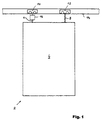
- Partition element 2 of a movable partition shown, which consists of several such partition elements.
- the Partition element 2 has a partition element sheet 4, for example be made of wood, glass or any other material and for example, can also contain a door (not shown).
- the partition element sheet 4 is in the illustrated embodiment via two support members 6, 8th suspended on roller carriages 10, 12, which are in a ceiling-side guide rail 14 run.
- the partition element 2 is along the ceiling side Guide rail 14 movable.
- the partition element 2 is driven by a drive device described in detail below, which too a part is housed in a housing 16, the part of the (according to FIG. 1 left) support member 6.
- the roller carriage 10 has rollers 18 on the side, which corresponding runway sections 14a run in the guide rail 14.
- the Support member 6, with which the partition element sheet 4, of which in Fig. 2 only the the upper part is shown schematically, is suspended on the roller carriage 10, has in addition to the housing 16, which can also be designed, for example, as a frame, still a support pin 20 which is rotatable with its upper end on the housing 16th stored and with its lower end on the upper part of the partition element sheet 4 is attached.
- the housing 16 is with a (preferably cylindrical) sleeve-shaped extension 16a with which the housing 16th is attached directly to the underside of the roller carriage 10.
- an electric motor 22 is accommodated in the housing 16, is part of the aforementioned drive device and its Output or output shaft 24 through the vertical sleeve-shaped extension 16a of the housing 16 in the direction of the roller carriage 10 lying thereover extends (the output shaft 24 of the electric motor 22 is dashed in Fig. 2 shown).
- the electric motor laterally on the support member 6 and in particular on the outside of its housing Arrange 16 to the lowest possible height of the support member 6 or its Obtain housing 16; in this case, the side of the housing 16 guided output shaft of the electric motor upwards via an angular gear be redirected.
- the T gear 26 arranged inside the roller carriage 10 has at least two extending on both sides of the roller carriage 10 Output shafts 30, which are coaxially coupled to the axes 32 of the rollers 18 are. Accordingly, the rotary motion generated by the electric motor 22 becomes its Output shaft 24 directly via the T-gear 26 arranged in the roller carriage 10 transferred to the rollers 18 of the roller carriage 10, which causes locomotion of the partition element along the guide rail 10 takes place.
- 14 power rails are on both sides of the guide rail 34 provided, on which corresponding sliding contacts 36 are present, which on a Arm 38 are arranged, which in the embodiment shown in Fig. 2 laterally is attached to the housing 16.
- the busbars 34 on the guide rail side are connected to an external voltage source (not shown) while the electric motor 22 is connected to the sliding contacts 36 (which is shown in FIG. 2 is also not shown).
- guide rail 14, busbar 34 and sliding contacts 36 and the housing 16 located below the guide rail 14 are from an outer housing 40 enclosed on its underside with a slot 42 is provided, through which the support pin 20 protrudes.
- the drive device described above which consists of the electric motor 22 and the T-gear 26 is in the embodiment shown in connection with the (according to FIG. 1 'left') support member 6 and the associated roller carriage 10 provided while in connection with the (according to Fig. 1 'right') support member 8 and the associated roller carriage 12 no further drive device is provided. Nevertheless, it is also conceivable to additionally or alternatively in Connection with the support member 8 and the associated roller carriage 12 or further support members a drive device of the type described above to provide.
Landscapes
- Engineering & Computer Science (AREA)
- Architecture (AREA)
- Physics & Mathematics (AREA)
- Electromagnetism (AREA)
- Civil Engineering (AREA)
- Structural Engineering (AREA)
- Power-Operated Mechanisms For Wings (AREA)
- Current-Collector Devices For Electrically Propelled Vehicles (AREA)
Abstract
Description
- Fig. 1
- schematisch ein Trennwandelement;
- Fig. 2
- eine Vorderansicht auf ein offenes Ende einer Führungsschiene und den Oberteil des Trennwandelementes von Fig. 1.
Claims (11)
- Trennwandelement einer entlang mindestens einer Transportschiene (14) verfahrbaren Raumtrennwand mit
mindestens einem in der Transportschiene (14) geführten Rollenwagen (10), dessen Rollen (18) sich mit einem Abschnitt (14a) der Transportschiene in Reibeingriff befinden, wobei das Trennwandelement (2) mit einer eigenen Antriebseinrichtung (22, 26) zur Fortbewegung entlang der Transportschiene (14) versehen ist,
dadurch gekennzeichnet,
daß die Antriebseinrichtung (22, 26) mindestens eine Rolle (18) des mindestens einen Rollenwagens (10) antreibt. - Trennwandelement nach Anspruch 1,
dadurch gekennzeichnet,
daß die Antriebseinrichtung (22, 26) mindestens eine drehbar angetriebene Ausgangswelle (30) aufweist, die zugleich die Achse (32) mindestens einer Rolle (18) eines Rollenwagens (10) bildet. - Trennwandelement nach Anspruch 1 oder 2,
bei welchem die Antriebseinrichtung (22, 26) einen Motor (22) aufweist,
dadurch gekennzeichnet,
daß die Antriebseinrichtung (22, 26) ferner ein Getriebe (26) aufweist, dessen Eingang (28) mit der Ausgangswelle (24) des Motors (22) gekoppelt ist, dessen Ausgang (30) mindestens eine Rolle (18) eines Rollenwagens (10) antreibt und das am oder im Rollenwagen (10) angeordnet ist. - Trennwandelement nach den Ansprüchen 2 und 3,
dadurch gekennzeichnet,
daß das Getriebe (26) als Winkel- oder T-Getriebe ausgebildet und der Motor (22) benachbart zum Rollenwagen (10) angeordnet ist. - Trennwandelement nach Anspruch 3 oder 4,
mit einem Trennwandelementblatt (4), das über ein Verbindungsorgan (6) am Rollenwagen (10) befestigt ist,
dadurch gekennzeichnet,
daß der Motor (22) am oder im Verbindungsorgan (6) angeordnet ist. - Trennwandelement nach Anspruch 5,
dadurch gekennzeichnet,
daß der Motor (22) in einem einen Teil des Verbindungsorgans (6) bildenden Rahmen oder Gehäuse (16) sitzt. - Trennwandelement nach Anspruch 6,
dadurch gekennzeichnet,
daß der Rahmen oder das Gehäuse (16) mit einem hohlen Abschnitt (16a) am Rollenwagen (10) befestigt ist und sich durch diesen hohlen Abschnitt (16a) die Ausgangswelle (24) des Motors (22) zur Kopplung mit dem Eingang (28) des Getriebes (26) erstreckt. - Trennwandelement nach mindestens einem der Ansprüche 5 bis 7, bei welchem das Trennwandelementblatt (4) über ein Tragorgan am Rollenwagen (10) aufgehängt ist,
dadurch gekennzeichnet,
daß das Verbindungsorgan (6) das Tragorgan ist. - Trennwandelement nach den Ansprüchen 7 und 8,
dadurch gekennzeichnet,
daß das Verbindungsorgan (6) ein Tragelement (20), vorzugsweise einen Tragbolzen, aufweist, mit dem das Trennwandelementblatt (4) am Rahmen oder Gehäuse (16) hängt. - Trennwandelement nach mindestens einem der Ansprüche 1 bis 9,
bei welchem die Antriebseinrichtung eine elektrische Antriebseinrichtung ist und eine Stromübertragungseinrichtung vorgesehen ist, die eine benachbart zur Transportschiene laufende Stromschienenanordnung und trennwandelementseitig eine sich mit der Stromschienenanordnung in elektrischem Kontakt befindliche Stromabnehmereinrichtung aufweist,
dadurch gekennzeichnet,
daß die Stromabnehmereinrichtung am Rollenwagen angeordnet ist. - Trennwandelement nach Anspruch 7 und gegebenenfalls Anspruch 8 oder 9,
bei welchem die Antriebseinrichtung (22, 26) eine elektrische Antriebseinrichtung ist und eine Stromübertragungseinrichtung (34, 36) vorgesehen ist, die eine benachbart zur Transportschiene (14) laufende Stromschienenanordnung (34) und trennwandelementseitig eine sich mit der Stromschienenanordnung (34) in elektrischem Kontakt befindliche Stromabnehmereinrichtung (36) aufweist,
dadurch gekennzeichnet,
daß die Stromabnehmereinrichtung (36) am Rahmen oder Gehäuse (16) angeordnet ist.
Applications Claiming Priority (2)
| Application Number | Priority Date | Filing Date | Title |
|---|---|---|---|
| DE29808916U DE29808916U1 (de) | 1998-05-16 | 1998-05-16 | Trennwandelement mit eigener Antriebseinrichtung |
| DE29808916U | 1998-05-16 |
Publications (2)
| Publication Number | Publication Date |
|---|---|
| EP0959219A2 true EP0959219A2 (de) | 1999-11-24 |
| EP0959219A3 EP0959219A3 (de) | 2001-11-07 |
Family
ID=8057298
Family Applications (1)
| Application Number | Title | Priority Date | Filing Date |
|---|---|---|---|
| EP99109531A Withdrawn EP0959219A3 (de) | 1998-05-16 | 1999-05-12 | Trennwandelement mit eigener Antriebseinrichtung |
Country Status (2)
| Country | Link |
|---|---|
| EP (1) | EP0959219A3 (de) |
| DE (1) | DE29808916U1 (de) |
Cited By (5)
| Publication number | Priority date | Publication date | Assignee | Title |
|---|---|---|---|---|
| WO2004005656A1 (de) * | 2002-07-05 | 2004-01-15 | Hawa Ag | Vorrichtung für verschiebbare trennelemente, laufwerk und trennelement |
| WO2007105057A3 (en) * | 2006-03-10 | 2007-11-15 | Pagliarani S R L Flli | Industrial door |
| WO2009152943A1 (de) * | 2008-06-19 | 2009-12-23 | Dorma Gmbh + Co. Kg | Antriebssystem zum antrieb und zur führung eines wandelementes für ein raumtrennwandsystem |
| DE102009011947A1 (de) | 2009-03-10 | 2010-09-16 | Dorma Gmbh + Co. Kg | Antriebssystem zum Antrieb und zur Führung eines Wandelelementes für ein Raumtrennwandsystem |
| US20120117756A1 (en) * | 2009-07-10 | 2012-05-17 | Dorma Gmbh + Co. Kg | Ceiling Track System For Guiding Wall Elements |
Citations (1)
| Publication number | Priority date | Publication date | Assignee | Title |
|---|---|---|---|---|
| DE2653328B1 (de) | 1974-02-01 | 1977-12-15 | Hueppe Justin Fa | Raumtrennwand aus versetzbaren starren wandelementen |
Family Cites Families (3)
| Publication number | Priority date | Publication date | Assignee | Title |
|---|---|---|---|---|
| DE2643905C2 (de) * | 1976-09-29 | 1978-10-19 | Siemens Ag, 1000 Berlin Und 8000 Muenchen | Raumteilungs-Wandelement mit motorischem Antrieb |
| DE9204436U1 (de) * | 1992-04-01 | 1992-05-27 | Goldbeck GmbH, 6382 Friedrichsdorf | An einer Decke o.dgl. aufhängbare Raumtrennwand sowie Rollenwagen hierfür |
| DE9214915U1 (de) * | 1992-11-03 | 1993-02-25 | abopart Viol und Partner GmbH & Co KG, 2903 Bad Zwischenahn | Versetzbare Trennwand mit mehreren plattenförmigen Wandelementen |
-
1998
- 1998-05-16 DE DE29808916U patent/DE29808916U1/de not_active Expired - Lifetime
-
1999
- 1999-05-12 EP EP99109531A patent/EP0959219A3/de not_active Withdrawn
Patent Citations (1)
| Publication number | Priority date | Publication date | Assignee | Title |
|---|---|---|---|---|
| DE2653328B1 (de) | 1974-02-01 | 1977-12-15 | Hueppe Justin Fa | Raumtrennwand aus versetzbaren starren wandelementen |
Cited By (14)
| Publication number | Priority date | Publication date | Assignee | Title |
|---|---|---|---|---|
| WO2004005656A1 (de) * | 2002-07-05 | 2004-01-15 | Hawa Ag | Vorrichtung für verschiebbare trennelemente, laufwerk und trennelement |
| AU2003233747B2 (en) * | 2002-07-05 | 2008-09-25 | Hawa Ag | Device for displaceable divider elements, running gear and divider element |
| AU2003233747B9 (en) * | 2002-07-05 | 2008-10-16 | Hawa Ag | Device for displaceable divider elements, running gear and divider element |
| US7578096B2 (en) | 2002-07-05 | 2009-08-25 | Hawa Ag | Apparatus for movable separating elements, a drive assembly and a separating element |
| WO2007105057A3 (en) * | 2006-03-10 | 2007-11-15 | Pagliarani S R L Flli | Industrial door |
| DE102008028831A1 (de) | 2008-06-19 | 2010-01-14 | Dorma Gmbh + Co. Kg | Antriebssystem zum Antrieb und zur Führung eines Wandelementes für ein Raumtrennwandsystem |
| WO2009152943A1 (de) * | 2008-06-19 | 2009-12-23 | Dorma Gmbh + Co. Kg | Antriebssystem zum antrieb und zur führung eines wandelementes für ein raumtrennwandsystem |
| DE102008028831B4 (de) * | 2008-06-19 | 2010-06-10 | Dorma Gmbh + Co. Kg | Antriebssystem zum Antrieb und zur Führung eines Wandelementes für ein Raumtrennwandsystem |
| DE102008028831C5 (de) * | 2008-06-19 | 2013-06-06 | Dorma Gmbh + Co. Kg | Antriebssystem zum Antrieb und zur Führung eines Wandelementes für ein Raumtrennwandsystem |
| US8479447B2 (en) | 2008-06-19 | 2013-07-09 | Dorma Gmbh +Co. Kg | Drive system for driving and for guiding a wall element for a room partitioning wall system |
| DE102009011947A1 (de) | 2009-03-10 | 2010-09-16 | Dorma Gmbh + Co. Kg | Antriebssystem zum Antrieb und zur Führung eines Wandelelementes für ein Raumtrennwandsystem |
| WO2010102730A1 (de) | 2009-03-10 | 2010-09-16 | Dorma Gmbh + Co. Kg | Antriebssystem zum antrieb und zur führung eines wandelementes für ein raumtrennwandsystem |
| US20120117756A1 (en) * | 2009-07-10 | 2012-05-17 | Dorma Gmbh + Co. Kg | Ceiling Track System For Guiding Wall Elements |
| US8584317B2 (en) * | 2009-07-10 | 2013-11-19 | Dorma Gmbh + Co. Kg | Ceiling track system for guiding wall elements |
Also Published As
| Publication number | Publication date |
|---|---|
| DE29808916U1 (de) | 1999-11-25 |
| EP0959219A3 (de) | 2001-11-07 |
Similar Documents
| Publication | Publication Date | Title |
|---|---|---|
| DE3303925C2 (de) | Massageeinrichtung | |
| DE3613074A1 (de) | Spritzling-entnahmevorrichtung fuer spritzgiessmaschinen | |
| DE3535608A1 (de) | Massagegeraet | |
| DE2404875B2 (de) | Raumtrennwand aus versetzbaren starren wandelementen | |
| DE2552085A1 (de) | Walzenschraemmaschine, die sich an einer ueber die streblaenge erstreckenden zahnstange entlangbewegt | |
| EP1031301A1 (de) | Verstellvorrichtung für einen Sitz oder eine Liege, insbesondere für ein Bett | |
| DE9418079U1 (de) | Freitragendes Schiebetor | |
| EP1197627B1 (de) | Antrieb für Tore, insbesondere Garagentore | |
| EP0434862A1 (de) | Aushebevorrichtung, insbesondere für Förderbahnen | |
| DE10304578B3 (de) | Einspritzaggregat für eine Spritzgießmaschine | |
| EP1681420A1 (de) | Fluegelanordnung mit Fahrfluegel und Festfluegel | |
| DE2846223C2 (de) | Arbeitstisch | |
| DE3103162A1 (de) | Foerdervorrichtung fuer lasten | |
| EP0959219A2 (de) | Trennwandelement mit eigener Antriebseinrichtung | |
| EP0008082A1 (de) | Garage zum Abstellen von Fahrzeugen übereinander | |
| EP1099878B1 (de) | Elektromotorische Verstellanordnung | |
| DE2140672C3 (de) | Garagentor | |
| DE69507133T2 (de) | Vorrichtung bei hängeförderern | |
| EP1258447A1 (de) | Personenfördervorrichtung mit direktangetriebenen Trittkörpern | |
| DE8532355U1 (de) | Trocknungsvorrichtung für die Trocknung von Kraftfahrzeugen in Fahrzeugwaschanlagen | |
| CH676658A5 (de) | ||
| EP0132448B1 (de) | Tisch mit verstellbarer Tischplatte | |
| DE1936521C3 (de) | Vorhangaufhängevorrichtung mit motorischem, insbesondere elektromotorischem Antrieb | |
| DE29608230U1 (de) | Scherenhubtisch | |
| DE4006133C1 (de) |
Legal Events
| Date | Code | Title | Description |
|---|---|---|---|
| PUAI | Public reference made under article 153(3) epc to a published international application that has entered the european phase |
Free format text: ORIGINAL CODE: 0009012 |
|
| AK | Designated contracting states |
Kind code of ref document: A2 Designated state(s): AT BE CH CY DE DK ES FI FR GB GR IE IT LI LU MC NL PT SE Kind code of ref document: A2 Designated state(s): AT BE CH DE ES FR GB IT LI LU NL SE |
|
| AX | Request for extension of the european patent |
Free format text: AL;LT;LV;MK;RO;SI |
|
| PUAL | Search report despatched |
Free format text: ORIGINAL CODE: 0009013 |
|
| AK | Designated contracting states |
Kind code of ref document: A3 Designated state(s): AT BE CH CY DE DK ES FI FR GB GR IE IT LI LU MC NL PT SE |
|
| AX | Request for extension of the european patent |
Free format text: AL;LT;LV;MK;RO;SI |
|
| RIC1 | Information provided on ipc code assigned before grant |
Free format text: 7E 05F 15/14 A, 7E 05D 15/06 B |
|
| 17P | Request for examination filed |
Effective date: 20020507 |
|
| AKX | Designation fees paid |
Free format text: AT BE CH DE ES FR GB IT LI LU NL SE |
|
| 17Q | First examination report despatched |
Effective date: 20050307 |
|
| RAP1 | Party data changed (applicant data changed or rights of an application transferred) |
Owner name: DORMA HOLDING GMBH & CO. KGAA |
|
| RAP1 | Party data changed (applicant data changed or rights of an application transferred) |
Owner name: DORMA GMBH + CO. KG |
|
| STAA | Information on the status of an ep patent application or granted ep patent |
Free format text: STATUS: THE APPLICATION HAS BEEN WITHDRAWN |
|
| 18W | Application withdrawn |
Effective date: 20071029 |