EP0958091B1 - Verfahren zum selbsttätigen mehrlagenschweissen - Google Patents
Verfahren zum selbsttätigen mehrlagenschweissen Download PDFInfo
- Publication number
- EP0958091B1 EP0958091B1 EP96943467A EP96943467A EP0958091B1 EP 0958091 B1 EP0958091 B1 EP 0958091B1 EP 96943467 A EP96943467 A EP 96943467A EP 96943467 A EP96943467 A EP 96943467A EP 0958091 B1 EP0958091 B1 EP 0958091B1
- Authority
- EP
- European Patent Office
- Prior art keywords
- joint
- cross
- bead
- beads
- section
- Prior art date
- Legal status (The legal status is an assumption and is not a legal conclusion. Google has not performed a legal analysis and makes no representation as to the accuracy of the status listed.)
- Expired - Lifetime
Links
Images



Classifications
-
- B—PERFORMING OPERATIONS; TRANSPORTING
- B23—MACHINE TOOLS; METAL-WORKING NOT OTHERWISE PROVIDED FOR
- B23K—SOLDERING OR UNSOLDERING; WELDING; CLADDING OR PLATING BY SOLDERING OR WELDING; CUTTING BY APPLYING HEAT LOCALLY, e.g. FLAME CUTTING; WORKING BY LASER BEAM
- B23K9/00—Arc welding or cutting
- B23K9/12—Automatic feeding or moving of electrodes or work for spot or seam welding or cutting
- B23K9/127—Means for tracking lines during arc welding or cutting
- B23K9/1272—Geometry oriented, e.g. beam optical trading
- B23K9/1274—Using non-contact, optical means, e.g. laser means
Definitions
- the deposition of two beads per layer is determined preferably only in dependency of the joint width at the level of the layer.
- Fig. 5 shows a diagram of calculated welding speeds with respect to different joint cross-sections.
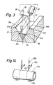
- Fig. 14 shows diagramatically a device for automatic multi-layer welding by means of two stationary weld heads.
- the distance of the tip 63 of the electrode to any one of the joint sides should have a set value I upon deposition of the bead 64 adjacent to the joint side. Should the distance exceed the set value the bead penetration into the basic material becomes inferior.
Landscapes
- Physics & Mathematics (AREA)
- Engineering & Computer Science (AREA)
- Optics & Photonics (AREA)
- Geometry (AREA)
- Plasma & Fusion (AREA)
- Mechanical Engineering (AREA)
- Butt Welding And Welding Of Specific Article (AREA)
- Arc Welding In General (AREA)
Claims (10)
- Verfahren zum automatischen Mehrlagenschweißen einer Verbindung (33), die von zwei Verbindungsflächen gebildet wird, wobei gemäß diesem Verfahren die Kontur der Verbindung in mehreren Querschnitten mittels eines Sensors (20), beispielsweise eines optischen oder mechanischen Sensors, bestimmt wird, der Signale emittiert, die die Kontur der Verbindung im aktuellen Querschnitt der Verbindung darstellen, wobei diese Signale nach der Auswertung das Setzen der Schweißraupen mittels einer kontinuierlich gespeisten Elektrode (32) steuern, die auf einen Schweißbereich in der Verbindung gerichtet ist, wobei bewirkt wird, dass der Sensor Punkte (41a-e, 42a-b) der gegenwärtigen Kontur der Verbindung in dem aktuellen Abschnitt misst, die im Wesentlichen den Querschnitt der Verbindung bilden und an den Verbindungsrändern, den Verbindungsseiten und der Verbindungsunterseite der Verbindung angeordnet sind, wobei eine Fläche, P pn, des durch diese gemessenen Punkte gebildeten Polygons berechnet wird, ein Mittelwert, P pm, dieser Polygonflächen berechnet wird, eine mittlere Menge an Schweißmaterial pro Längeneinheit entsprechend dem Mittelwert der Polygonflächen der Querschnitte der Verbindung bestimmt wird, und eine Menge an Schweißmaterial pro Längeneinheit für jeden Querschnitt der Verbindung als Funktion der mittleren Menge an Schweißmaterial pro Längeneinheit und des Verhältnisses der Polygonfläche, P pn, des Querschnitts der Verbindung zu dem Mittelwert der Polygonflächen, P pm, berechnet wird,a) wobei die Menge an Schweißmaterial pro Längeneinheit variiert wird als eine Funktion von:a1) einer Drahtvorschubgeschwindigkeit (V t x pn) und/odera2) einer Schweißgeschwindigkeit (V pn) undb) wobei eine Zwischenlage gebildet wird, indem wenigstens drei Schweißraupen (80, 81, 83) in der Verbindung gesetzt werden,
gekennzeichnet durch:c) Bestimmen des Abstandes zwischen den Mittelpunkten der Schweißraupen, eines Schweißabstandes (L pn) bezüglich jedes Querschnitts der Verbindung als Funktion eines symmetrischen Schweißabstands, L0, und:c1) des Neigungskoeffizienten, k spn, einer Verbindungslinie des aktuellen Querschnitts der Verbindung, die die Ränder der Verbindung miteinander verbindet, und/oderc2) des Neigungskoeffizienten, k fpn, der aktuellen Verbindungsunterseite, wobei L0= b/Z ist und b die Breite der Verbindungsunterseite des aktuellen Querschnitts der Verbindung ist und Z die Zahl der Schweißraupen in dem aktuellen Querschnitt der Verbindung ist. - Verfahren nach Patentanspruch 1, bei dem wenigstens zwei Schweißraupen (84, 85) in der Verbindung gesetzt werden, um eine Zwischenlage zu bilden, wenn der Mittelwert der Werte, die der Breite der Verbindung in den verschiedenen Querschnitten der Verbindung auf der Höhe der Zwischenlage entsprechen, einen gesetzten Wert übersteigt, das durch die Messpunkte bestimmte Polygon in dem letzten Fall von einer Vertikale (87) durch die Verbindung in einen ersten und einen zweiten Teil (88, 89) des Polygons geteilt wird, die die Messpunkte jeweils an ihrer Verbindungsseite und an ihrem Verbindungsrand umfassen, die Drahtvorschubgeschwindigkeit (V t x pn) für die Schweißraupen, die an einer bzw. der anderen Verbindungsseite zu setzen sind, bezüglich jedes Querschnitts der Verbindung als Funktion der berechneten mittleren Drahtvorschubgeschwindigkeit (V tpnm) für den aktuellen Querschnitt der Verbindung und des Verhältnisses zwischen den Teilpolygonflächen bestimmt wird.
- Verfahren nach einem der Patentansprüche 1 oder 2, bei dem die Schweißgeschwindigkeit (V pn) für die verschiedenen Querschnitte der Verbindung konstant ist, d.h. die Schweißgeschwindigkeit variiert in der Längsrichtung der Verbindung nicht, während die mittlere Drahtvorschubgeschwindigkeit (V tpnm) in der Längsrichtung der Verbindung variiert, wobei eine durchschnittliche Drahtvorschubgeschwindigkeit (V tpnm) bestimmt wird, die dem Mittelwert der Polygonflächen der Querschnitte der Verbindung entspricht, und die mittlere Drahtvorschubgeschwindigkeit (V tpnm) für die jeweiligen Querschnitte der Verbindung als eine Funktion der durchschnittlichen mittleren Drahtvorschubgeschwindigkeit (V tpnm) und des Verhältnisses der Polygonfläche, P pn, des aktuellen Querschnitts der Verbindung zu dem Mittelwert, P pm, der Polygonflächen berechnet wird.
- Verfahren nach einem der Patenansprüche 1 oder 2, bei dem die mittlere Drahtvorschubgeschwindigkeit (V tpnm) und die Schweißgeschwindigkeit (V pn) in der Längsrichtung der Verbindung variieren, wobei eine durchschnittliche mittlere Drahtvorschubgeschwindigkeit (V tpnm) bestimmt wird, die dem Mittelwert der Polygonflächen der Querschnitte der Verbindung entspricht, und die mittlere Drahtvorschubgeschwindigkeit (V tpnm) für den jeweiligen Querschnitt der Verbindung als Funktion der durchschnittlichen mittleren Drahtvorschubgeschwindigkeit (V tpnm) und des Verhältnisses der Polygonfläche, P pn, des aktuellen Querschnitts der Verbindung zu dem Mittelwert, P pm, der Polygonflächen berechnet wird, während eine gesetzte mittlere Schweißgeschwindigkeit, V pm, mit dem Mittelwert der Polygonflächen der Querschnitte der Verbindung in Zusammenhang steht und die Schweißgeschwindigkeit (V pn) für die jeweiligen Querschnitte der Verbindung als Funktion der mittleren Schweißgeschwindigkeit und des Verhältnisses des Mittelwerts, P pm, der Polygonflächen zu der Polygonfläche, P pn, des aktuellen Querschnitts der Verbindung berechnet wird.
- Verfahren nach einem der Patentansprüche 1-4, bei dem der Wert, der für die Polygonfläche, P Lpn, der Zwischenlage in jedem Querschnitt der Verbindung als Funktion der Eckpunkte (P2, P3, P5, P6) der Polygonfläche berechnet wird, wobei die Eckpunkte (P2 und P3), die die Schnittpunkte zwischen der Verbindungsunterseite und den Verbindungsseiten der Zwischenlage sind, während des Setzens der Raupe (80) gemessen werden, die bei dieser Lage an eine der Verbindungsseiten in einem vorher bestimmten Abstand (I) von der Verbindungsseite gesetzt wird, während der Eckpunkt (P5), der der Schnittpunkt zwischen der Oberseite der ersten gesetzten Raupe und der einen Verbindungsseite ist, während des Setzens der Raupe (81) gemessen wird, die unmittelbar danach an die andere Verbindungsseite gesetzt wird, während der Eckpunkt (P6), der der Schnittpunkt zwischen der Oberseite der Raupe, die an die andere Verbindungsseite gesetzt wird, und der anderen Verbindungsseite ist, mittels einer gemessenen Höhe, h1, der ersten gesetzten Raupe gemessen wird, die gemäß der Formel

- Verfahren nach Patentanspruch 5, bei dem die Raupen der Zwischenlage im Vergleich zu der vorhergehenden Lage um eine Raupe erhöht werden können, falls die berechnete Polygonfläche, P Lpn, der Zwischenlage größer als S0 ·(Z+l) ist, wobei S0 die Nenn-Raupenfläche ist, Z die Zahl der Raupen in der vorgehenden Lage ist und l eine Konstante, z.B. 0,5, ist.
- Verfahren nach einem der Patentansprüche 5 oder 6, bei dem die Raupenflächen der zusätzlichen Raupen in derselben Zwischenlage erzielt werden, indem die Raupenflächen der beiden Raupen (84, 85), die an die Verbindungsseiten gesetzt werden, interpoliert werden, und die entsprechenden Drahtvorschubgeschwindigkeiten (V t x pn) proportional zu den Raupenflächen (S x pn) sind.
- Verfahren nach einem der Patentansprüche 1-7, bei dem die Position der Schweißraupen in jedem Querschnitt der Verbindung erzielt wird, indem die Schweißraupen, die den Verbindungsseiten am nächsten gelegen sind, so positioniert werden, dass das gewünschte Eindringen in die Seiten erzielt wird, während die Position der Zwischenraupen mit Hilfe des Abstands zwischen den Raupenznittelpunkten, d.h. des Schweißabstands L pn, gemäß der Formel berechnet wird:


- Verfahren nach einem der Patentansprüche 1-8, bei dem nach dem Setzen einer Zwischenlage in der Verbindung und vor dem Setzen der nachfolgenden Lage der Quotient aus dem Mittelwert, P pm, der Polygonflächen, P pn, der Querschnitte der übrigen Querschnitte (90) der Verbindung und dem Mittelwert der Querschnittsflächen (91) der zuletzt gesetzten Zwischenlage in allen Querschnitten der Verbindung berechnet wird, und bei dem oberste Raupen in einer obersten Lage in der Verbindung oben auf der Zwischenlage gesetzt werden, wenn der Quotient weniger als einen gesetzten Wert beträgt, bevorzugt weniger als 0,7.
- Verfahren nach Patentanspruch 9, bei dem die Zahl der Raupen in der obersten Lage im Vergleich zu der Zahl der zuletzt gesetzten Zwischenlage um eins erhöht wird, wenn die Fläche, Ac, der obersten Lage die Bedingung Ac>S0·Z·V tmax/V tpnm erfüllt, wobei S0 die Nenn-Raupenfläche, Z die Zahl der Raupen in der zuletzt gesetzten Zwischenlage, V tpnm die durchschnittliche mittlere Drahtvorschubgeschwindigkeit und V tmax die höchste denkbare Drahtvorschubgeschwindigkeit ist.
Applications Claiming Priority (3)
| Application Number | Priority Date | Filing Date | Title |
|---|---|---|---|
| SE9504607 | 1995-12-22 | ||
| SE9504607A SE515773C2 (sv) | 1995-12-22 | 1995-12-22 | Förfarande vid automatisk flerskiktssvetsning |
| PCT/SE1996/001721 WO1997023324A1 (en) | 1995-12-22 | 1996-12-20 | Method for automatic multi-layer welding |
Publications (2)
| Publication Number | Publication Date |
|---|---|
| EP0958091A1 EP0958091A1 (de) | 1999-11-24 |
| EP0958091B1 true EP0958091B1 (de) | 2006-11-29 |
Family
ID=20400688
Family Applications (1)
| Application Number | Title | Priority Date | Filing Date |
|---|---|---|---|
| EP96943467A Expired - Lifetime EP0958091B1 (de) | 1995-12-22 | 1996-12-20 | Verfahren zum selbsttätigen mehrlagenschweissen |
Country Status (8)
| Country | Link |
|---|---|
| US (1) | US6155475A (de) |
| EP (1) | EP0958091B1 (de) |
| JP (1) | JP2000502612A (de) |
| AU (1) | AU1219397A (de) |
| CA (1) | CA2240105C (de) |
| DE (1) | DE69636740T2 (de) |
| SE (1) | SE515773C2 (de) |
| WO (1) | WO1997023324A1 (de) |
Families Citing this family (96)
| Publication number | Priority date | Publication date | Assignee | Title |
|---|---|---|---|---|
| US6545243B1 (en) | 2001-09-14 | 2003-04-08 | Delco Remy America, Inc. | Dynamic weld power termination for hot-staking armature commutators |
| US6909066B2 (en) * | 2003-07-30 | 2005-06-21 | Edison Welding Institute | Adaptive and synergic fill welding method and apparatus |
| DE102004039410A1 (de) * | 2004-08-13 | 2006-02-23 | Precitec Kg | Verfahren und Vorrichtung zur Regelung eines automatischen Bearbeitungsprozesses |
| US9104195B2 (en) | 2006-12-20 | 2015-08-11 | Lincoln Global, Inc. | Welding job sequencer |
| US9937577B2 (en) | 2006-12-20 | 2018-04-10 | Lincoln Global, Inc. | System for a welding sequencer |
| US10994358B2 (en) | 2006-12-20 | 2021-05-04 | Lincoln Global, Inc. | System and method for creating or modifying a welding sequence based on non-real world weld data |
| US8927901B2 (en) * | 2008-03-17 | 2015-01-06 | Alcoa Inc. | Buried-arc welding of metal work pieces with through-the-arc seam tracking |
| WO2009146359A1 (en) | 2008-05-28 | 2009-12-03 | Illinois Tool Works Inc. | Welding training system |
| US9280913B2 (en) | 2009-07-10 | 2016-03-08 | Lincoln Global, Inc. | Systems and methods providing enhanced education and training in a virtual reality environment |
| US9483959B2 (en) * | 2008-08-21 | 2016-11-01 | Lincoln Global, Inc. | Welding simulator |
| US9196169B2 (en) | 2008-08-21 | 2015-11-24 | Lincoln Global, Inc. | Importing and analyzing external data using a virtual reality welding system |
| US8747116B2 (en) * | 2008-08-21 | 2014-06-10 | Lincoln Global, Inc. | System and method providing arc welding training in a real-time simulated virtual reality environment using real-time weld puddle feedback |
| US8884177B2 (en) | 2009-11-13 | 2014-11-11 | Lincoln Global, Inc. | Systems, methods, and apparatuses for monitoring weld quality |
| US9318026B2 (en) | 2008-08-21 | 2016-04-19 | Lincoln Global, Inc. | Systems and methods providing an enhanced user experience in a real-time simulated virtual reality welding environment |
| US9330575B2 (en) | 2008-08-21 | 2016-05-03 | Lincoln Global, Inc. | Tablet-based welding simulator |
| US8915740B2 (en) * | 2008-08-21 | 2014-12-23 | Lincoln Global, Inc. | Virtual reality pipe welding simulator |
| US8834168B2 (en) | 2008-08-21 | 2014-09-16 | Lincoln Global, Inc. | System and method providing combined virtual reality arc welding and three-dimensional (3D) viewing |
| US8851896B2 (en) | 2008-08-21 | 2014-10-07 | Lincoln Global, Inc. | Virtual reality GTAW and pipe welding simulator and setup |
| US8911237B2 (en) | 2008-08-21 | 2014-12-16 | Lincoln Global, Inc. | Virtual reality pipe welding simulator and setup |
| US8274013B2 (en) | 2009-03-09 | 2012-09-25 | Lincoln Global, Inc. | System for tracking and analyzing welding activity |
| US8552337B2 (en) | 2009-06-11 | 2013-10-08 | Illinois Tool Works Inc. | Weld defect detection systems and methods for laser hybrid welding |
| US9221117B2 (en) | 2009-07-08 | 2015-12-29 | Lincoln Global, Inc. | System for characterizing manual welding operations |
| US9773429B2 (en) | 2009-07-08 | 2017-09-26 | Lincoln Global, Inc. | System and method for manual welder training |
| US9011154B2 (en) | 2009-07-10 | 2015-04-21 | Lincoln Global, Inc. | Virtual welding system |
| US10748447B2 (en) | 2013-05-24 | 2020-08-18 | Lincoln Global, Inc. | Systems and methods providing a computerized eyewear device to aid in welding |
| SE533066C2 (sv) * | 2009-08-24 | 2010-06-22 | Esab Ab | Anordning och förfarande för automatisk flersträngssvetsning |
| US8569655B2 (en) | 2009-10-13 | 2013-10-29 | Lincoln Global, Inc. | Welding helmet with integral user interface |
| US9468988B2 (en) | 2009-11-13 | 2016-10-18 | Lincoln Global, Inc. | Systems, methods, and apparatuses for monitoring weld quality |
| US8569646B2 (en) | 2009-11-13 | 2013-10-29 | Lincoln Global, Inc. | Systems, methods, and apparatuses for monitoring weld quality |
| PL2632625T3 (pl) * | 2010-10-28 | 2021-08-30 | Esab Ab | Urządzenie spawalnicze |
| CA2821671C (en) | 2010-12-13 | 2018-01-09 | Edison Welding Institute, Inc. | Welding training system |
| DE102011006532A1 (de) * | 2011-03-31 | 2012-10-04 | Bayerische Motoren Werke Aktiengesellschaft | Schweißvorrichtung |
| US9101994B2 (en) | 2011-08-10 | 2015-08-11 | Illinois Tool Works Inc. | System and device for welding training |
| US9573215B2 (en) | 2012-02-10 | 2017-02-21 | Illinois Tool Works Inc. | Sound-based weld travel speed sensing system and method |
| US9126287B2 (en) * | 2012-03-12 | 2015-09-08 | Siemens Energy, Inc. | Advanced pass progression for build-up welding |
| CN103521965A (zh) * | 2012-07-03 | 2014-01-22 | 通用电气公司 | 自动焊接系统及方法 |
| US20160093233A1 (en) | 2012-07-06 | 2016-03-31 | Lincoln Global, Inc. | System for characterizing manual welding operations on pipe and other curved structures |
| US9767712B2 (en) | 2012-07-10 | 2017-09-19 | Lincoln Global, Inc. | Virtual reality pipe welding simulator and setup |
| US9583014B2 (en) | 2012-11-09 | 2017-02-28 | Illinois Tool Works Inc. | System and device for welding training |
| US9368045B2 (en) | 2012-11-09 | 2016-06-14 | Illinois Tool Works Inc. | System and device for welding training |
| US9728103B2 (en) | 2013-03-15 | 2017-08-08 | Illinois Tool Works Inc. | Data storage and analysis for a welding training system |
| US9666100B2 (en) | 2013-03-15 | 2017-05-30 | Illinois Tool Works Inc. | Calibration devices for a welding training system |
| US9713852B2 (en) | 2013-03-15 | 2017-07-25 | Illinois Tool Works Inc. | Welding training systems and devices |
| US9583023B2 (en) | 2013-03-15 | 2017-02-28 | Illinois Tool Works Inc. | Welding torch for a welding training system |
| US9672757B2 (en) | 2013-03-15 | 2017-06-06 | Illinois Tool Works Inc. | Multi-mode software and method for a welding training system |
| US10930174B2 (en) | 2013-05-24 | 2021-02-23 | Lincoln Global, Inc. | Systems and methods providing a computerized eyewear device to aid in welding |
| US11090753B2 (en) | 2013-06-21 | 2021-08-17 | Illinois Tool Works Inc. | System and method for determining weld travel speed |
| US20150072323A1 (en) | 2013-09-11 | 2015-03-12 | Lincoln Global, Inc. | Learning management system for a real-time simulated virtual reality welding training environment |
| US10083627B2 (en) | 2013-11-05 | 2018-09-25 | Lincoln Global, Inc. | Virtual reality and real welding training system and method |
| US20150132143A1 (en) * | 2013-11-11 | 2015-05-14 | Gerald J. Bruck | Welding process and reduced restraint weld joint |
| US10056010B2 (en) | 2013-12-03 | 2018-08-21 | Illinois Tool Works Inc. | Systems and methods for a weld training system |
| US9589481B2 (en) | 2014-01-07 | 2017-03-07 | Illinois Tool Works Inc. | Welding software for detection and control of devices and for analysis of data |
| US10105782B2 (en) | 2014-01-07 | 2018-10-23 | Illinois Tool Works Inc. | Feedback from a welding torch of a welding system |
| US9751149B2 (en) | 2014-01-07 | 2017-09-05 | Illinois Tool Works Inc. | Welding stand for a welding system |
| US9757819B2 (en) | 2014-01-07 | 2017-09-12 | Illinois Tool Works Inc. | Calibration tool and method for a welding system |
| US10170019B2 (en) | 2014-01-07 | 2019-01-01 | Illinois Tool Works Inc. | Feedback from a welding torch of a welding system |
| US9724788B2 (en) | 2014-01-07 | 2017-08-08 | Illinois Tool Works Inc. | Electrical assemblies for a welding system |
| US9836987B2 (en) | 2014-02-14 | 2017-12-05 | Lincoln Global, Inc. | Virtual reality pipe welding simulator and setup |
| KR101622676B1 (ko) * | 2014-04-17 | 2016-05-20 | 대우조선해양 주식회사 | 수평 맞대기 이음 대용착 용접 장치 및 방법 |
| WO2015185972A1 (en) | 2014-06-02 | 2015-12-10 | Lincoln Global, Inc. | System and method for manual welder training |
| CN104002021A (zh) * | 2014-06-06 | 2014-08-27 | 哈尔滨工业大学 | 用于多层多道焊道自动识别与跟踪的装置 |
| US9862049B2 (en) | 2014-06-27 | 2018-01-09 | Illinois Tool Works Inc. | System and method of welding system operator identification |
| US10665128B2 (en) | 2014-06-27 | 2020-05-26 | Illinois Tool Works Inc. | System and method of monitoring welding information |
| US9937578B2 (en) | 2014-06-27 | 2018-04-10 | Illinois Tool Works Inc. | System and method for remote welding training |
| US10307853B2 (en) | 2014-06-27 | 2019-06-04 | Illinois Tool Works Inc. | System and method for managing welding data |
| US11154946B2 (en) | 2014-06-30 | 2021-10-26 | Illinois Tool Works Inc. | Systems and methods for the control of welding parameters |
| US9724787B2 (en) | 2014-08-07 | 2017-08-08 | Illinois Tool Works Inc. | System and method of monitoring a welding environment |
| US11014183B2 (en) | 2014-08-07 | 2021-05-25 | Illinois Tool Works Inc. | System and method of marking a welding workpiece |
| JP6437758B2 (ja) * | 2014-08-12 | 2018-12-12 | Ntn株式会社 | 等速自在継手の接合タイプ外側継手部材の検査装置 |
| US9875665B2 (en) | 2014-08-18 | 2018-01-23 | Illinois Tool Works Inc. | Weld training system and method |
| US10239147B2 (en) | 2014-10-16 | 2019-03-26 | Illinois Tool Works Inc. | Sensor-based power controls for a welding system |
| US11247289B2 (en) | 2014-10-16 | 2022-02-15 | Illinois Tool Works Inc. | Remote power supply parameter adjustment |
| US10490098B2 (en) | 2014-11-05 | 2019-11-26 | Illinois Tool Works Inc. | System and method of recording multi-run data |
| US10417934B2 (en) | 2014-11-05 | 2019-09-17 | Illinois Tool Works Inc. | System and method of reviewing weld data |
| US10373304B2 (en) | 2014-11-05 | 2019-08-06 | Illinois Tool Works Inc. | System and method of arranging welding device markers |
| US10402959B2 (en) | 2014-11-05 | 2019-09-03 | Illinois Tool Works Inc. | System and method of active torch marker control |
| US10210773B2 (en) | 2014-11-05 | 2019-02-19 | Illinois Tool Works Inc. | System and method for welding torch display |
| US10204406B2 (en) | 2014-11-05 | 2019-02-12 | Illinois Tool Works Inc. | System and method of controlling welding system camera exposure and marker illumination |
| US10427239B2 (en) | 2015-04-02 | 2019-10-01 | Illinois Tool Works Inc. | Systems and methods for tracking weld training arc parameters |
| US10373517B2 (en) | 2015-08-12 | 2019-08-06 | Illinois Tool Works Inc. | Simulation stick welding electrode holder systems and methods |
| US10657839B2 (en) | 2015-08-12 | 2020-05-19 | Illinois Tool Works Inc. | Stick welding electrode holders with real-time feedback features |
| US10593230B2 (en) | 2015-08-12 | 2020-03-17 | Illinois Tool Works Inc. | Stick welding electrode holder systems and methods |
| US10438505B2 (en) | 2015-08-12 | 2019-10-08 | Illinois Tool Works | Welding training system interface |
| JP6794596B2 (ja) * | 2016-07-04 | 2020-12-02 | 株式会社神戸製鋼所 | 下向き溶接における溶接条件作成方法 |
| EP3319066A1 (de) | 2016-11-04 | 2018-05-09 | Lincoln Global, Inc. | Magnetische frequenzwahl für elektromagnetische positionsverfolgung |
| US10878591B2 (en) | 2016-11-07 | 2020-12-29 | Lincoln Global, Inc. | Welding trainer utilizing a head up display to display simulated and real-world objects |
| US10913125B2 (en) | 2016-11-07 | 2021-02-09 | Lincoln Global, Inc. | Welding system providing visual and audio cues to a welding helmet with a display |
| GB2558274B (en) * | 2016-12-23 | 2019-04-17 | Caterpillar Shrewsbury Ltd | Method of remanufacturing a cylinder head |
| CN106891111B (zh) * | 2017-03-23 | 2019-01-22 | 北京航空航天大学 | 一种用于膜式水冷壁销钉焊接的机器人闭环加工系统 |
| US10997872B2 (en) | 2017-06-01 | 2021-05-04 | Lincoln Global, Inc. | Spring-loaded tip assembly to support simulated shielded metal arc welding |
| US11557223B2 (en) | 2018-04-19 | 2023-01-17 | Lincoln Global, Inc. | Modular and reconfigurable chassis for simulated welding training |
| US11475792B2 (en) | 2018-04-19 | 2022-10-18 | Lincoln Global, Inc. | Welding simulator with dual-user configuration |
| US11288978B2 (en) | 2019-07-22 | 2022-03-29 | Illinois Tool Works Inc. | Gas tungsten arc welding training systems |
| US11776423B2 (en) | 2019-07-22 | 2023-10-03 | Illinois Tool Works Inc. | Connection boxes for gas tungsten arc welding training systems |
| CN110814467A (zh) * | 2019-12-03 | 2020-02-21 | 天津工业大学 | 一种消除电弧增材制造构件边缘塌陷的路径修正方法 |
| US12521884B2 (en) * | 2022-07-26 | 2026-01-13 | Path Robotics, Inc. | Techniques for multipass welding |
Family Cites Families (15)
| Publication number | Priority date | Publication date | Assignee | Title |
|---|---|---|---|---|
| US4186864A (en) * | 1976-10-29 | 1980-02-05 | Hitachi, Ltd. | Method for producing a welded joint |
| IT1100853B (it) * | 1978-12-22 | 1985-09-28 | Breda Termomeccanica Spa | Procedimento e apparecchiatura per la saldatura automatica di giunti su lamiere di grosso spessore |
| US4508953A (en) * | 1982-04-27 | 1985-04-02 | Kabushiki Kaisha Kobe Seiko Sho | Method of multi-layer welding |
| JPS60174274A (ja) * | 1984-02-20 | 1985-09-07 | Fanuc Ltd | 三次元曲面におけるスケ−リング方法 |
| JPS60255271A (ja) * | 1984-05-31 | 1985-12-16 | Nippon Kokan Kk <Nkk> | 多層溶接の制御方法 |
| GB2180183B (en) * | 1985-07-31 | 1989-09-06 | Mitsubishi Electric Corp | Automatic welding machine correcting for a variable groove width |
| DE3545505C2 (de) * | 1985-12-20 | 1995-08-10 | Kuka Schweissanlagen & Roboter | Verfahren und Vorrichtung zum Aufsuchen und Verfolgen einer Kehlnaht beim Schutzgas-Lichtbogenschweißen |
| EP0266424B1 (de) * | 1986-03-20 | 1995-12-06 | Shin Meiwa Industry Co., Ltd. | Verfahren und anordnung zur regelung eines schweissroboters |
| US4988201A (en) * | 1988-09-14 | 1991-01-29 | Nkk Corporation | Apparatus for detecting a shape of a groove |
| US5173592A (en) * | 1989-02-23 | 1992-12-22 | Kabushiki Kaisha Yaskawa Denki Seisakusho | Method and apparatus for multi-layer welding |
| US5030812A (en) * | 1989-06-13 | 1991-07-09 | Nkk Corporation | Method for one-side root pass welding of a pipe joint |
| US5166495A (en) * | 1989-09-11 | 1992-11-24 | Esab Aktiebolag | Method and apparatus for automatic multi-run welding |
| SE8902963L (sv) * | 1989-09-11 | 1991-03-15 | Esab Ab | Saett vid automatisk flerstraengsvetsning |
| JPH0810949A (ja) * | 1994-06-23 | 1996-01-16 | Fanuc Ltd | 多層盛り溶接における溶接ロボットシステムの制御方法 |
| US5841104A (en) * | 1996-09-03 | 1998-11-24 | Abb Flexible Automation, Inc. | Method and system for multiple pass welding |
-
1995
- 1995-12-22 SE SE9504607A patent/SE515773C2/sv not_active IP Right Cessation
-
1996
- 1996-12-20 JP JP9523578A patent/JP2000502612A/ja active Pending
- 1996-12-20 AU AU12193/97A patent/AU1219397A/en not_active Abandoned
- 1996-12-20 CA CA002240105A patent/CA2240105C/en not_active Expired - Lifetime
- 1996-12-20 WO PCT/SE1996/001721 patent/WO1997023324A1/en not_active Ceased
- 1996-12-20 US US09/091,920 patent/US6155475A/en not_active Expired - Lifetime
- 1996-12-20 EP EP96943467A patent/EP0958091B1/de not_active Expired - Lifetime
- 1996-12-20 DE DE69636740T patent/DE69636740T2/de not_active Expired - Lifetime
Also Published As
| Publication number | Publication date |
|---|---|
| CA2240105C (en) | 2008-02-26 |
| WO1997023324A1 (en) | 1997-07-03 |
| SE9504607L (sv) | 1997-06-23 |
| AU1219397A (en) | 1997-07-17 |
| CA2240105A1 (en) | 1997-07-03 |
| DE69636740D1 (de) | 2007-01-11 |
| US6155475A (en) | 2000-12-05 |
| EP0958091A1 (de) | 1999-11-24 |
| SE515773C2 (sv) | 2001-10-08 |
| SE9504607D0 (sv) | 1995-12-22 |
| DE69636740T2 (de) | 2007-10-18 |
| JP2000502612A (ja) | 2000-03-07 |
Similar Documents
| Publication | Publication Date | Title |
|---|---|---|
| US6155475A (en) | Method for automatic multi-layer welding | |
| EP0423088B1 (de) | Verfahren zur automatischen Mehrlagenschweissung | |
| CA1288824C (en) | Method and apparatus for continuous production of tubular bodies by means of laser longitudinal seam welding | |
| IT9020229A1 (it) | Rilevamento e controllo dell'angolo di bagnatura di un cordone di saldatura | |
| US4724302A (en) | Bead process control with profiler | |
| US11498157B2 (en) | System and method of enhanced automated welding of first and second workpieces | |
| US5166495A (en) | Method and apparatus for automatic multi-run welding | |
| AU4865000A (en) | Method and system for welding railroad rails | |
| CA1302515C (en) | Automatic arc-welding method | |
| US4816641A (en) | Automatic arc-welding method | |
| CN117644327B (zh) | 一种自动焊接系统 | |
| CA1132402A (en) | Z-bar guide apparatus | |
| CN117680796A (zh) | 不锈钢复合板智能化埋弧焊焊接方法及系统 | |
| CN121339623A (zh) | 一种b型套筒的焊接控制系统及方法 | |
| JPH0999368A (ja) | 自動溶接装置 | |
| CN117532226B (zh) | 一种多层道厚壁构件机器人焊接层道智能规划方法 | |
| JPH10216940A (ja) | 多層盛溶接の制御方法及び多層盛溶接装置 | |
| CN116021182B (zh) | 一种激光复合焊间隙超差自适应调节系统 | |
| EP0049037B1 (de) | Verfahren und Vorrichtung zum Tiefkehlschweissen dicker Rohre | |
| JPH09108838A (ja) | 溶接装置 | |
| CN106181159A (zh) | 坡口焊缝机器人平焊焊接方法 | |
| SU719825A1 (ru) | Способ исследовани стыковых соединений | |
| US20260138201A1 (en) | Adaptive welding | |
| GB1579700A (en) | Method of arc welding of metal members from one side only | |
| JPH071167A (ja) | 複合熱源溶接におけるシーム倣い制御方法 |
Legal Events
| Date | Code | Title | Description |
|---|---|---|---|
| PUAI | Public reference made under article 153(3) epc to a published international application that has entered the european phase |
Free format text: ORIGINAL CODE: 0009012 |
|
| 17P | Request for examination filed |
Effective date: 19980528 |
|
| AK | Designated contracting states |
Kind code of ref document: A1 Designated state(s): DE FR GB IT |
|
| AX | Request for extension of the european patent |
Free format text: RO PAYMENT 19980528;SI PAYMENT 19980528 |
|
| 17Q | First examination report despatched |
Effective date: 20020715 |
|
| 18D | Application deemed to be withdrawn |
Effective date: 20050506 |
|
| D18D | Application deemed to be withdrawn (deleted) | ||
| GRAP | Despatch of communication of intention to grant a patent |
Free format text: ORIGINAL CODE: EPIDOSNIGR1 |
|
| GRAS | Grant fee paid |
Free format text: ORIGINAL CODE: EPIDOSNIGR3 |
|
| GRAA | (expected) grant |
Free format text: ORIGINAL CODE: 0009210 |
|
| AK | Designated contracting states |
Kind code of ref document: B1 Designated state(s): DE FR GB IT |
|
| AX | Request for extension of the european patent |
Extension state: RO SI |
|
| REF | Corresponds to: |
Ref document number: 69636740 Country of ref document: DE Date of ref document: 20070111 Kind code of ref document: P |
|
| ET | Fr: translation filed | ||
| PLBE | No opposition filed within time limit |
Free format text: ORIGINAL CODE: 0009261 |
|
| STAA | Information on the status of an ep patent application or granted ep patent |
Free format text: STATUS: NO OPPOSITION FILED WITHIN TIME LIMIT |
|
| 26N | No opposition filed |
Effective date: 20070830 |
|
| REG | Reference to a national code |
Ref country code: FR Ref legal event code: PLFP Year of fee payment: 20 |
|
| PGFP | Annual fee paid to national office [announced via postgrant information from national office to epo] |
Ref country code: GB Payment date: 20151229 Year of fee payment: 20 |
|
| PGFP | Annual fee paid to national office [announced via postgrant information from national office to epo] |
Ref country code: FR Payment date: 20151217 Year of fee payment: 20 |
|
| PGFP | Annual fee paid to national office [announced via postgrant information from national office to epo] |
Ref country code: DE Payment date: 20151229 Year of fee payment: 20 |
|
| REG | Reference to a national code |
Ref country code: DE Ref legal event code: R071 Ref document number: 69636740 Country of ref document: DE |
|
| PG25 | Lapsed in a contracting state [announced via postgrant information from national office to epo] |
Ref country code: IT Free format text: LAPSE BECAUSE OF NON-PAYMENT OF DUE FEES Effective date: 20151220 |
|
| REG | Reference to a national code |
Ref country code: GB Ref legal event code: PE20 Expiry date: 20161219 |
|
| PG25 | Lapsed in a contracting state [announced via postgrant information from national office to epo] |
Ref country code: GB Free format text: LAPSE BECAUSE OF EXPIRATION OF PROTECTION Effective date: 20161219 |
|
| PG25 | Lapsed in a contracting state [announced via postgrant information from national office to epo] |
Ref country code: IT Free format text: LAPSE BECAUSE OF NON-PAYMENT OF DUE FEES Effective date: 20151220 |
|
| PGFP | Annual fee paid to national office [announced via postgrant information from national office to epo] |
Ref country code: IT Payment date: 20151222 Year of fee payment: 20 |
|
| PGRI | Patent reinstated in contracting state [announced from national office to epo] |
Ref country code: IT Effective date: 20170710 |