EP0957747B1 - Sensor,verfahren und vorrichtung für optische blutoxymetrie - Google Patents
Sensor,verfahren und vorrichtung für optische blutoxymetrie Download PDFInfo
- Publication number
- EP0957747B1 EP0957747B1 EP19960916287 EP96916287A EP0957747B1 EP 0957747 B1 EP0957747 B1 EP 0957747B1 EP 19960916287 EP19960916287 EP 19960916287 EP 96916287 A EP96916287 A EP 96916287A EP 0957747 B1 EP0957747 B1 EP 0957747B1
- Authority
- EP
- European Patent Office
- Prior art keywords
- light
- sensor
- detector
- terminals
- tissue
- Prior art date
- Legal status (The legal status is an assumption and is not a legal conclusion. Google has not performed a legal analysis and makes no representation as to the accuracy of the status listed.)
- Expired - Lifetime
Links
Images
Classifications
-
- A—HUMAN NECESSITIES
- A61—MEDICAL OR VETERINARY SCIENCE; HYGIENE
- A61B—DIAGNOSIS; SURGERY; IDENTIFICATION
- A61B5/00—Measuring for diagnostic purposes; Identification of persons
- A61B5/145—Measuring characteristics of blood in vivo, e.g. gas concentration or pH-value ; Measuring characteristics of body fluids or tissues, e.g. interstitial fluid or cerebral tissue
- A61B5/1455—Measuring characteristics of blood in vivo, e.g. gas concentration or pH-value ; Measuring characteristics of body fluids or tissues, e.g. interstitial fluid or cerebral tissue using optical sensors, e.g. spectral photometrical oximeters
- A61B5/14551—Measuring characteristics of blood in vivo, e.g. gas concentration or pH-value ; Measuring characteristics of body fluids or tissues, e.g. interstitial fluid or cerebral tissue using optical sensors, e.g. spectral photometrical oximeters for measuring blood gases
- A61B5/14552—Details of sensors specially adapted therefor
-
- A—HUMAN NECESSITIES
- A61—MEDICAL OR VETERINARY SCIENCE; HYGIENE
- A61B—DIAGNOSIS; SURGERY; IDENTIFICATION
- A61B2562/00—Details of sensors; Constructional details of sensor housings or probes; Accessories for sensors
- A61B2562/02—Details of sensors specially adapted for in-vivo measurements
- A61B2562/0233—Special features of optical sensors or probes classified in A61B5/00
-
- A—HUMAN NECESSITIES
- A61—MEDICAL OR VETERINARY SCIENCE; HYGIENE
- A61B—DIAGNOSIS; SURGERY; IDENTIFICATION
- A61B2562/00—Details of sensors; Constructional details of sensor housings or probes; Accessories for sensors
- A61B2562/04—Arrangements of multiple sensors of the same type
- A61B2562/046—Arrangements of multiple sensors of the same type in a matrix array
-
- G—PHYSICS
- G01—MEASURING; TESTING
- G01N—INVESTIGATING OR ANALYSING MATERIALS BY DETERMINING THEIR CHEMICAL OR PHYSICAL PROPERTIES
- G01N21/00—Investigating or analysing materials by the use of optical means, i.e. using sub-millimetre waves, infrared, visible or ultraviolet light
- G01N21/17—Systems in which incident light is modified in accordance with the properties of the material investigated
- G01N21/47—Scattering, i.e. diffuse reflection
- G01N21/4738—Diffuse reflection, e.g. also for testing fluids, fibrous materials
- G01N21/474—Details of optical heads therefor, e.g. using optical fibres
- G01N2021/4742—Details of optical heads therefor, e.g. using optical fibres comprising optical fibres
- G01N2021/4747—Concentric bundles
Definitions
- the present invention relates to a novel sensor for non-invasive optical blood oximetry, such as blood pulse oximetry effected on a blood perfused tissue; to a method of optical oximetry; and to a device suitable for performing the method.
- SaO 2 oxygen saturation
- a tissue under investigation is illuminated by light having at least two components of different wavelengths, and the measurements are based upon the following two physical phenomena:
- the pulsatile absorbance component of a tissue layer located between the light source and the sensor characterizes the degree of oxygen saturation of arterial blood.
- the prior art discloses two types of optical sensors which are associated with and serve for two modes of performing optical blood oximetry: transmission pulse oximetry in which so-called transmissive sensors are used and reflection pulse oximetry in which so-called reflectance or transflectance sensors are used.
- transmission pulse oximetry one measures light passing across a blood perfused tissue such as a finger, an ear or the like by placing a light emitter and the detection of a transmissive sensor at two opposite sides of the tissue under examination, as described for example in US 4,938,213.
- reflectance or transflectance sensors can be used which comprise both light emitters and light detectors which are accordingly placed on one and the same side of the tissue under examination, as described, for example, in US 5,228,440, 5,247,932, 5,099,842 and in WO 90/01293. Reference to the two types of sensors can also be found, for example, in US 5,247,932 and in "Fetal Oxygen Saturation Monitoring" sponsored by NELLCOR.
- the transmission and the reflection modes of operation have specific limitations of applicability and their accuracy in general, and in specific applications in particular is not satisfactory.
- the transmission technology can be successfully applied only in cases where the tissue to be investigated forms a distinctive protrusion which makes it possible to apply a light emitter and a light sensor at opposite surfaces.
- the reflection technology is the one most commonly resorted to, notably in fetal oximetry.
- accuracy of the conventional reflection technology is rather low in comparison with that of the transmission one, because the degree of diffusion of the emitted light in the tissue is unknown, which means that the nature of the functional interdependence between a light signal received by the sensor and the degree of blood oxygen saturation is also unknown.
- Another disadvantage of the known reflection technology is a partial shunting of the emitted light on the surface of the tissue between the source and the sensor, and a specular reflection created by the superficial layer of the tissue.
- U.S. Patent No. 5,009,842 describes a sensor with means for overcoming the problem of shunting of the emitted light on the outer surface of the tissue between the light source and the detector.
- U.K. Patent Application No. 2 269 012 proposes to select and separate light signals resulting from light reflection by a superficial layer of a blood perfused tissue such as skin or hair, essentially by choosing a particular distance between the locations of emitting and detecting optical fibers on the contacted surface of the tissue under examination.
- Fetal oximeters usually comprise applicators which generally include a plate with at least one substantially point-like light source and at least one substantially point-like light detector suitably spaced from the light source(s).
- applicators which generally include a plate with at least one substantially point-like light source and at least one substantially point-like light detector suitably spaced from the light source(s).
- One drawback of such applicators is that if the applicator is applied to a non-uniform section of the skin, such as a hairy portion or a birthmark, the light signal received by the detector(s) will be distorted.
- LEDs are either installed in the probe itself such as, for example, in US 4,938,218 or linked to the probes via optical fibers such as, for example, in US 5,099,842, GB-A-2 269 012, WO 91/18549 and WO 90/01293.
- Such light sources may provide, for example, a pair of wavelengths of 700 nm and 800 nm which are suitable for the purposes of blood oximetry.
- the accuracy of oximetric measurements increases the closer the two wavelengths are to each other, nevertheless within the wavelength range required for oximetry LEDs are incapable of providing two wavelengths closer to each other than 100 nm.
- a sensor according to the preamble of claim 1 is known from US-A-5 273 036.
- the objects of the present invention are achieved by ensuring that the light paths of light components with different wavelengths, emitted by at least two distinct light emitters, will always be substantially equal to each other irrespective of the nature of the skin and of the underlying tissue and also irrespective of variations in physiological conditions.
- a sensor according to the present invention is defined in claim 1.
- any local disturbances in the tissue structure which in case of a prior art point-like detector would result in significant deviation of the optical path, will not affect the intrinsic average optical path of light of a given wavelength.
- the annular shape of the detector and the geometry of the sensor ensure the stability of the optical paths for each given wavelength.
- the applicator block has a second essentially annular light detector terminal spaced from and concentric with said first light detector terminal.
- the said light emitters may each be a light source positioned within the applicator block, or alternatively a light emitter terminal having a free, light emitting end and being coupled via another end to a light source.
- the light emitter terminals are in form of bundles of optical fibers.
- the light emitting ends of the light emitter terminals should be point-like means that they should each have a small area.
- the two terminals will be complementary to each other forming together a circular plate having a diameter of the order of 1 mm.
- the light detector(s) of a sensor according to the invention may, for example, comprise a plurality of photo-diodes.
- Examples of light sources in a sensor according to the present invention are laser diodes capable of producing at least two distinct powerful monochromatic light radiation with very close wavelengths, within the range of from 670 to 940 nm and preferably 750 to 800 nm, differing from each other by say, 10 - 20 nm.
- a first laser diode emits at 750-760 nm and a second laser diode at 780-800 nm.
- Such characteristics are not available in light sources, such as LEDs used in conventional oximetry apparatuses.
- the laser diodes have the further advantage of enabling a more linear absorption by the tissues of monochromatic light of any wavelength within the intrinsic emission range.
- the use of laser diodes in the optical sensors according to the invention enables to fulfil a basic requirement of oximetry, namely the optical paths equivalence at different wavelengths of radiation.
- the carrier body of a sensor according to the invention is opaque.
- said applicator block in a carrier body of a sensor comprises an axial, throughgoing bore perpendicular to said contact surface and holding said light emitter terminals, and at least one substantially annular space concentrically surrounding said bore and accommodating each a light detector terminal.
- each light detector terminal is placed within said substantially annular space of said applicator block such that the free light acquiring ends thereof are sunk within the accommodating annular space and removed from said contact surface, whereby a free portion of said annular space constitutes a collimator that rejects specular reflection.
- the distance by which the free ends are removed from the contact surface is so selected, that only light arriving from a relatively deep layer of the blood perfused tissue and directed substantially parallel to the axis of the applicator block is acquired, while the specular reflection from the superficial layer of the tissue, which is substantially divergent from the axis, is rejected.
- Each light detector terminal comprises optical fibers with obliquely cut light-acquiring ends. In this way the sensitivity of the sensor is improved whereby a working light signal reflected from even relatively deep and remote layers of the tissue under investigation can be perceived.
- At least one of the annular spaces holding said first and second annular detector terminals are slanting with their side walls flaring out towards the contact surface such that the said obliquely cut light-acquiring ends of the detector terminal constituting optical fibers are flush with or parallel to the contact surface.
- an optical fiber with an obliquely cut light-acquiring end generally rejects light rays arriving at a part of the end close to the shorter side wall of the fiber and acquires light rays arriving at a part of the end closer to the longer side wall.
- optical fibers have ever been used in sensors for optical blood oximetry.
- the geometry of the optical fibers enables to increase the area of the tissue at which the light detector terminals may still acquire working optical signals.
- the optical fibers that constitute an annular light detector terminal have obliquely cut light-acquiring ends, the terminal is capable of acquiring working signals from an annular detection zone of the tissue that has a larger inner radius than that of the detector terminal ring.
- the light detector terminals described hereinabove reject the slanting light rays appearing between the light emitter and light detector terminals, while at the same time enhancing the acquisition of light coming out from relatively deep blood perfused layers of the tissue. Accordingly, such a sensor has an improved sensitivity without it having been necessary to increase the distance between the light emitter and detector terminals and consequently also with no need to increase the prescribed limited size of the sensor body.
- the detector terminal constituting optical fibers each have an obliquely cut, light-acquiring end inclined towards a plane perpendicular to the longitudinal fiber axis by an acute angle.
- this acute angle does not exceed about 42°, and is preferably within the range of about 20°-22°.
- the carrier body of the sensor may be of any suitable shape, e.g. cylindrical, and holds at one end the said applicator block so that the contact surface of the latter forms one end face of the body.
- pulsatile changes of the value of absorption of the light by the blood perfused tissue are used to determine the characteristics of interest, the pulsatile changes being conventionally determined on the basis of the relationship between the intensity of the emitted light and that of the light detected by a single detector.
- the pulsatile changes are determined, on the basis of measured relation between intensities of light acquired by at least one pair of detector terminals differently distanced from the light emitting terminals.
- the detector terminal closest to the emitter terminals may be considered with respect to the second, more distanced detector terminal as a quasi light emitter terminal.
- the novel sensor embodiment in which the light detector terminals are arranged in two concentric rings around the light emitter terminals, the detector terminals define between them a tubular section of the tissue which is quasi-transmissively illuminated by light emanating from the emitters. Accordingly, such a sensor according to the invention may be described as a reflectance sensor that simulates a transmissive one.
- the optical paths of illumination provided by the two real emitter terminals are similarly affected by any kind of optical disturbance in the annular detection zone, independent of the wavelength of the emitted light and of the distance of the emitter terminals from the first annular detector terminal. Accordingly, substantial equivalence of optical traces will automatically be achieved for any location of the sensor on the skin and also in case of changing physiological conditions in the underlying tissue.
- a method according to the invention is defined in claim 14.
- the said light emitters may each be a light source positioned within the applicator block, or alternatively a light emitter terminal having a free, light emitting end and being coupled via another end to a light source.
- the light emitter terminals are in form of bundles of optical fibers.
- the above method is applicable for determining oxygen saturation in the arterial blood.
- a pulsatile component of the light absorbance at each one of the wavelengths results from the fluctuating volume of arterial blood in the tissue section between the first light detector and the second light detector, and therefore this pulsatile absorbance component is indicative of the degree of oxygen saturation.
- the procedure pursuant to these measurements comprises:
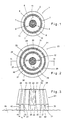
- Fig. 1 shows the contact surface of an applicator block of a carrier body in a sensor according to the invention.
- block I which is assumed to be made from an opaque material such as a metal, has a contact surface 2 and a central bore 3 holding two bundles of optical fibers 4 and 5 serving as light emitter terminals.
- Bundles 4 and 5 are coupled each to a laser diode (not shown) and are thus capable of emitting light at two distinct wavelengths.
- An essentially annular space 6 provided in block 1 and consisting of a number of segments 7 with intermittent braces 8 concentrically surrounds the central bore 3 and accommodates a plurality of optical fibers 9 forming together an annular light detector terminal.
- optical fibers are assumed to be bundled together in a manner not shown and are coupled to a detector device, e.g. a photodiode, equally not shown.
- Braces 8 of block 1 connect the median section 10 and the peripheral section 11 of the block with each other.
- the light-acquiring ends of the light detector constituting optical fibers 9 may either be flush with the contact surface 2 or alternatively be removed from the surface inwards by a desired distance.
- the two light emitter terminals 4 and 5 emit light on to a tissue under investigation, and the detector (not shown) transforms and modulates the light acquired by the light-acquiring ends of the optical fibers 9 into an electric signal suitable for further processing.
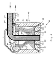
- FIGs. 2 and 3 illustrate schematically another embodiment of an applicator block in a carrier body of an optical sensor according to the invention.
- an applicator block 20 has a contact surface 21 and a central bore 22 holding two bundles 23 and 24 of optical fibers which constitute two light emitter terminals and which are connected to a pair of light sources (not shown).
- the light emitting ends 25 and 26 of the light emitter terminals 23 and 24 are withdrawn inside bore 22 and are thus removed from the contact surface 21.
- Block 20 further comprises a first annular space 27 concentric with bore 22 and consisting of four segments 28 with intermittent bracing members 29 linking with each other the core section 30 and median section 31 of block 20.
- the first annular space 27 houses a plurality of optical fibers 32 constituting together a light detector terminal and have each a light-acquiring end 33.
- a second annular space 35 surrounds concentrically the first annular space 27 and similar to the latter consists of four segments 36 with intermittent bracing members 37 connecting the median block section 31 with a peripheral section 38.
- the second annular space 35 houses a plurality of optical fibers 39 which together constitute a second light detector terminal and have each a light-acquiring end 40. As shown in Fig. 3 the light-acquiring ends 40 are removed from the contact surface 21.
- the empty portions 41 of the annular space 27 and 42 of the annular space 35 serve as collimators for light returning from a tissue under examination.
- each of the two light emitting terminals 23 and 24 is hemi-circular, the two terminals being complementary and form together a circular plate having a diameter of say 1 mm.
- the diameters of the first and second annular spaces may respectively be 5 and 7 mm.
- the two light emitter terminals are linked to two distinct light sources (not shown) generating light of different wavelengths and the two light detector terminals constituted by the optical fibers 32 and 39 located respectively in the annular spaces 27 and 35, are linked to optical detector devices (not shown).
- sensor 20 is applied to a skin portion above a tissue 44 which is sequentially illuminated via the light emitting terminal by the two light sources which are not shown and which may, for example, be laser diodes emitting light at the two wavelengths of about 750 and 780 nm.
- the light is absorbed and partially reflected by the tissue and the pulsatile changes of the light absorption in the annular section A of tissue 44 may be estimated by comparing the integral light signal received by the first light detector terminal constituted by the optical fibers 32 with the integral light signal received by the second light detector terminal constituted by the optical fibers 39.
- a ratio of the intensities of these integral signals characterizes a degree of attenuation of the light in the annular section A of the tissue, for a specific wavelength.
- the mentioned ratio obtained for each of the applied wavelengths are then used for determining the desired characteristics such as the oxygen saturation of the blood in the tissue 44.
- Fig. 4 illustrates schematically an axial cross-sectional view of a modified sensor 50 comprising an opaque, generally cylindrical body 51 having an applicator block 52 with a contact surface 53.
- Block 52 has a central axial bore 54 holding the lower end portion of a tube 55 merging into a horizontal portion 56 and accommodating one optical fiber bundle marked 57, guiding at least two light sources (not shown) to light emitting terminals.
- Block 52 further comprises first and second annular slots 58 and 59 concentric with bore 54, adjacent block and body portions being suitably linked to each other in a manner not shown.
- the slots 58 and 59 are slanting, flaring out in the direction of the contact surface 53 such that the adjacent block portions 60 and 61 have frusto-conical shapes as shown.
- Slots 58 and 59 accommodate the free, light-acquiring ends of first and second optical fiber bundles 63 and 64 which constitute first and second detector terminals and pass through the inner space of body 51 to photodetectors 65 electrically connected through wires 67 to a cable 68.
- Each of the light-acquiring ends of the optical fibers of bundles 63 and 64 terminates with an oblique cut, forming an acute angle with the axis of the fiber such that the light-acquiring end of each fiber is either flush with or parallel to the contact surface 53.
- tube 56 In operation the outer end portion of tube 56 is coupled to two light sources (not shown).
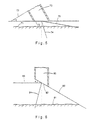
- Fig. 5 schematically illustrates a scope of vision of an optic fiber 70 which faces a surface 71 of a tissue with its obliquely cut surface 72.
- Fiber 70 is assumed to form part of the bundle 63 in Fig. 4.
- the fiber 70 is characterized by an acute angle ⁇ formed between the cut end face 72 and a plane 73 perpendicular to the fiber's axis.
- the actual scope of vision of the fiber 70 extends between a left-hand ray 74 and a right-hand ray 75 and may be calculated from the angle ⁇ and the optical parameters of the fiber.
- the specular reflection and shunted light which mostly come to the surface 72 from left of the ray 74 will not be perceived by the detector.
- the detector will perceive light arriving from the reflective deep layers of the tissue in directions substantially perpendicular to surface 71 in a rather wide area confined between rays 74 and 75.
- the scope of vision of the cut-ended optic fiber 70 is shifted in the direction of its longer side wall portion. It has been found by the inventors, that the fiber 70 is adequate when the angle ⁇ is not greater than about 42°, and is most effective when the angle ⁇ is within the range of from about 20° to about 22°. More particularly, an oblique cut with an angle ⁇ of about 20° to about 22° also increases sharply the distance of vision.
- Fig. 6 is a schematical illustration of a cut-ended optical fiber 80 which, in distinction from fiber 70 in Fig. 5, the fiber axis is perpendicular to a surface 81 of a tissue. However, the oblique cut 82 of the fiber 80 while facing the surface 81, is not parallel to it, an acute angle ⁇ being formed between the surface 82 of the cut and a plane 83 that is parallel to surface 81 and accordingly perpendicular to the fiber's axis. Similar as in the embodiment of Fig. 5, angle ⁇ determines the scope of vision of the fiber 80, which is defined by a left-hand beam 84 and a right-hand beam 85. In analogy to the fiber of Fib. 5, the scope of vision of the cut-ended optic fiber 80 is shifted from the shorter to the longer side wall. The same limitations to the value of angle ⁇ apply as in Fig. 5.
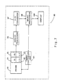
- Fig. 7 is a block diagram of one embodiment of an oximeter 90 according to the invention.
- the oximeter 90 comprises a probe 91 including two light sources 92 and 93, e.g. two laser diodes, generating light of two different wavelengths for the sequential illumination of a tissue under investigation.
- the probe further comprises two photodetectors 94 and 95.
- the light signals received from the two light detectors 94 and 95 are transformed and modulated into electric signals which are amplified by an analogue processing unit 96, digitized by an A/D converter 97 and transmitted to a microprocessor 98 for computing the characteristic of interest which is displayed on a display 100.
- Light sources 92 and 93 of probe 91 are controlled by the microprocessor 98 via a timing controller unit 101.
- the procedure of measurement of the characteristic of interest by the oximeter 90 is as follows.
- the calculations are performed at two points of time on a pulsating light intensity graph, representing the pulsatile arterial blood component, the first being the nil (minimum) point, and the second the crest (maximum) point thereof.
- the measurements and calculations include the following six steps:
- two intensity ratios N and M are determined at the two different points of time, namely N1 and N2 for the nil point and M1 and M2 for the crest point of the pulsatile arterial blood pressure component.
- the first intensity ratios N1 and M1 for the two points are based on the light signals' intensities registered by the first and second light detectors at the first wavelength and the second intensity ratios N2 and M2 for the two points are based on the light signals' intensities registered by the first and second detectors at the second wavelength.
- a characteristic AC of a pulsatile component of the signal is defined, namely AC1 for the first wavelength and AC2 for the second wavelength, each of AC1 and AC2 being the difference between the intensity ratios calculated, respectively, for the crest and nil points at that particular wavelength.
- the characteristic DC of a constant component of the signal is computed, namely DC1 for the first wavelength and DC2 for the second wavelength, each of DC1 and DC2 being the average from two intensity ratios calculated, respectively, at the nil and crest points at a given wavelength.
- the microprocessor then calculates:
- the first light source 92 is a laser diode emitting at 755 nm. and the second light source 93 is a laser diode emitting at 785 nm.
Landscapes
- Health & Medical Sciences (AREA)
- Physics & Mathematics (AREA)
- Life Sciences & Earth Sciences (AREA)
- Biomedical Technology (AREA)
- Medical Informatics (AREA)
- Biophysics (AREA)
- Pathology (AREA)
- Engineering & Computer Science (AREA)
- Spectroscopy & Molecular Physics (AREA)
- Heart & Thoracic Surgery (AREA)
- Optics & Photonics (AREA)
- Molecular Biology (AREA)
- Surgery (AREA)
- Animal Behavior & Ethology (AREA)
- General Health & Medical Sciences (AREA)
- Public Health (AREA)
- Veterinary Medicine (AREA)
- Measurement Of The Respiration, Hearing Ability, Form, And Blood Characteristics Of Living Organisms (AREA)
- Investigating Or Analysing Materials By Optical Means (AREA)
Claims (45)
- Sensor zur nicht invasiven optischen Blutoxymetrie, umfassend:dadurch gekennzeichnet, dasseinen Applikatorblock (1) mit einer Kontaktfläche (2), welche geeignet ist, einem durchbluteten Körpergewebe gegenüberzuliegen, wobei der Applikatorblock (1) wenigstens zwei Lichtemitter (4, 5), welche in nächster Nähe zueinander positioniert und geeignet sind, Licht von jeweiligen punktähnlichen Lichtemitterendstücken bei Wellenlängen, welche voneinander verschieden sind, zu emittieren, undwenigstens ein erstes, im Wesentlichen ringförmiges Lichtdetektorendstück (9), welches die wenigstens zwei Lichtemitter (4, 5) konzentrisch umgibt und mit einem Lichtdetektor verbunden ist, umfasst,
das Lichtdetektorendstück (9) ein Bündel von optischen Fasern umfasst, welche jeweils ein freies, Licht erfassendes Ende zur Erfassung von Licht, welches von dem Körpergewebe ankommt, aufweisen, und
das Licht erfassende Ende schräg abgeschnitten ist. - Sensor gemäß Anspruch 1, wobei der Applikatorblock (1) Teil eines Trägerkörpers ist und eine axiale durchgehende Bohrung (3), welche senkrecht zur Kontaktfläche (2) ist und die Lichtemitter (4, 5) aufnimmt, und wenigstens einen im Wesentlichen ringförmigen Raum (6) umfasst, welcher die Bohrung (3) konzentrisch umgibt und ein Lichtdetektorendstück (9) aufnimmt, und wobei das Licht erfassende Ende ein freies Ende ist, welches in dem ringförmigen Raum so angeordnet ist, dass es Erfassung von Licht, welches von tiefen durchbluteten Schichten des Gewebes reflektiert wird, in Bezug auf Licht, welches von anderen Schichten reflektiert wird, verbessert.
- Sensor gemäß Anspruch 2, wobei die optischen Fasern des Lichtdetektorendstückes (9) über ein anderes Ende mit einem Lichtdetektor verbunden sind.
- Sensor gemäß Anspruch 2 oder 3, wobei der Applikatorblock (20) ein zweites im Wesentlichen ringförmiges Lichtdetektorendstück (39) aufweist, welches vom ersten Lichtdetektorendstück (32) beabstandet und konzentrisch dazu ist, wobei das zweite Lichtdetektorendstück (39) in einem zweiten im Wesentlich ringförmigen Raum (35) liegt, die Bohrung (22) und den ersten ringförmigen Raum (27) konzentrisch umgibt und mit einem zweiten Lichtdetektor verbunden ist.
- Sensor gemäß einem der Ansprüche 2 bis 4, wobei jedes der Lichtdetektorendstücke (32, 39) innerhalb des jeweiligen im Wesentlichen ringförmigen Raumes (27, 35) des Applikatorblocks (20) auf eine derartige Weise angeordnet ist, dass das Licht erfassende Ende des Lichtdetektorendstückes (32, 39) innerhalb des ringförmigen Aufnahmeraums (27, 35) auf eine zurückgezogene Weise positioniert ist, um von der Kontaktfläche (21) entfernt zu sein, wodurch ein freier Abschnitt (41, 42) des ringförmigen Raumes (27, 35) einen Kollimator zur Unterdrückung von spiegelnder Reflexion bildet.
- Sensor gemäß einem der Ansprüche 2 bis 5, wobei der Lichtdetektor eine Photodiode umfasst.
- Sensor gemäß einem der Ansprüche 1 bis 6, wobei jede der optischen Fasern, welche einen der Detektorendstücke (63, 64) bilden, ihr Licht erfassendes Ende so aufweist, dass es schräg abgeschnitten und zu einer Ebene (73, 83), welche senkrecht zu einer Faserlängsachse ist, in einem spitzen Winkel (α) geneigt ist.
- Sensor gemäß Anspruch 7, wobei wenigstens einer der ringförmigen Räume (58, 59), welche die ersten und zweiten ringförmigen Detektorendstücke aufnehmen, schräg verläuft, wobei seine Seite trichterförmig aufweitend zur Kontaktfläche (53) fällt, so dass die schräg abgeschnittenen, Licht erfassenden Enden der optischen Fasern mit der Kontaktfläche (53) bündig oder parallel dazu sind.
- Sensor gemäß einem der vorhergehenden Ansprüche,
wobei die Lichtemitter (4, 5) Lichtquellen umfassen, welche innerhalb des Applikatorblocks (1) positioniert sind. - Sensor gemäß einem der vorhergehenden Ansprüche,
wobei die Lichtemitter (4, 5) jeweils ein Lichtemitterendstück umfassen, welches ein freies, Licht emittierendes Ende aufweist und über ein anderes Ende mit einer Lichtquelle verbunden ist. - Sensor gemäß einem der vorhergehenden Ansprüche,
wobei die Lichtemitterendstücke jeweils ein Bündel von optischen Fasern umfassen. - Sensor gemäß einem der vorhergehenden Ansprüche,
wobei die Lichtquellen Laserdioden umfassen, welche jeweils geeignet sind, monochromatisches Licht innerhalb eines Wellenlängenbereichs von 670 nm bis 940 nm zu emittieren. - Sensor gemäß Anspruch 12, wobei eine erste Lichtquelle geeignet ist, bei einer Wellenlänge von 750 nm bis 760 nm zu emittieren, und eine zweite geeignet ist, bei einer Wellenlänge von 780 nm bis 800 nm zu emittieren.
- Verfahren zur nicht invasiven optischen Blutpulsoxymetrie in einem durchbluteten Körpergewebe, wobei das Verfahren umfasst:Bereitstellen eines Sensors gemäß Anspruch 4 oder einem der Ansprüche 5 bis 13, wenn von Anspruch 4 abhängig;Positionieren des Applikatorblocks (1) auf einem Hautabschnitt eines Untersuchungsobjekts, dessen darunter liegende Gewebe zu untersuchen sind, wobei die Kontaktfläche (2) der Haut gegenüberliegt;sequentielles Emittieren von Licht bei wenigstens zwei verschiedenen Wellenlängen von den Emittern (4, 5) zum Körpergewebe;Kollimieren von Licht, welches von dem zu untersuchenden Gewebe ankommt und bei einer der beiden verschiedenen Wellenlängen emittiert wurde, bei Unterdrücken von spiegelnder Reflexion und Querlicht;Erkennen einer Intensität des kollimierten Lichts, wobei die Erkennung durch integrale Erfassung der Lichtsignale durch die wenigstens zwei Lichtdetektorendstücke einzeln und gleichzeitig erfolgt;Bestimmen von Verhältnissen zwischen der Lichtintensität, welche durch die wenigstens zwei Lichtdetektorendstücke bei jeder der wenigstens zwei verschiedenen Wellenlängen erkannt wurde; undBestimmen eines Wertes von Sauerstoffsättigung des Blutes auf der Basis der Verhältnisse.
- Verfahren gemäß Anspruch 14, umfassend:wobei K1 und K2 Kalibrierkonstanten sind.Auswählen von zwei Zeitpunkten zur Durchführung von Messungen, wobei ein erster Punkt ein Nullpunkt einer pulsierenden arteriellen Blutkomponente ist und ein zweiter Punkt ein Gipfelpunkt davon ist;Durchführen von Messungen, welche Beleuchten mit Licht einer ersten der Wellenlängen und gleichzeitiges Aufzeichnen von Signalen, welche vom Gewebe ankommen, mit den ersten und zweiten Lichtdetektoren und anschließendes Beleuchten mit Licht einer zweiten der Wellenlängen und gleichzeitiges Aufzeichnen von Signalen, welche vom Gewebe ankommen, mit den ersten und zweiten Lichtdetektoren umfassen, an jedem der ersten und zweiten Punkte;Bestimmen von zwei Lichtintensitätsverhältnissen für jeden der beiden Zeitpunkte, wobei ein erstes der Intensitätsverhältnisse zwischen Lichtsignalintensitäten, welche durch die ersten und zweiten Lichtdetektoren bei der ersten Wellenlänge aufgezeichnet wurden, liegt und das zweite Intensitätsverhältnis zwischen Lichtsignalintensitäten, welche durch die ersten und zweiten Lichtdetektoren bei der zweiten Wellenlänge aufgezeichnet wurden, liegt;Ausrechnen von ersten und zweiten pulsierenden Komponenten AC1 und AC2 des Lichtsignals für jede der ersten und zweiten Wellenlängen, wobei jede eine Differenz zwischen dem Intensitätsverhältnis ist, welches bei den Gipfel- und Nullpunkten für die jeweilige Wellenlänge berechnet wurde;Ausrechnen von ersten und zweiten konstanten Komponenten DC1 und DC2 der Lichtsignale für jede der ersten und zweiten Wellenlängen, wobei jede ein Durchschnitt der Intensitätsverhältnisse ist, welche bei den Gipfel- und Nullpunkten für die jeweiligen Wellenlängen berechnet wurden; undBerechnen einer Sauerstoffsättigung von arteriellem Blut SaO2 gemäß der folgenden Gleichung:
- Vorrichtung zur nicht invasiven optischen Blutpulsoxymetrie, umfassend:den optischen Sensor gemäß einem der Ansprüche 1 bis 13;wenigstens zwei Lichtquellen, welche mit den Lichtemitterendstücken verbunden und geeignet sind, Licht bei wenigstens zwei verschiedenen Wellenlängen zu emittieren;wenigstens zwei optische Detektoren, welche mit wenigstens zwei im Wesentlichen ringförmigen Detektorendstücken verbunden sind;Steuermittel, welche geeignet sind, zu bewirken, dass die wenigstens zwei Lichtquellen das Gewebe über die Emitterendstücke fortlaufend beleuchten, und gleichzeitige Messungen einer Intensität von Licht, welches durch die wenigstens zwei Detektoren über die wenigstens zwei Detektorendstücke erfasst wurde, zu erhalten; undProzessormittel zum Bestimmen von Charakteristiken von Interesse aus den Ergebnissen der gleichzeitigen Messungen.
- Vorrichtung gemäß Anspruch 16, wobei der optische Sensor der Sensor gemäß einem der Ansprüche 4 bis 6 ist.
- Sensor gemäß Anspruch 1, wobei die ersten und zweiten Emitter (4, 5) in einem Applikatorblock (1) so angeordnet sind, dass sie eine erste Region des durchbluteten Gewebes bestrahlen, der Sensor ferner einen ersten Detektor umfasst, welcher mit dem Lichtdetektorendstück (9) optisch verbunden ist, und der erste Detektor geeignet ist, ein erstes Ausgangssignal zu erzeugen, das einer Intensität von Licht entspricht, welches über das Lichtdetektorendstück (9) an den ersten Detektor übertragen wurde, wobei das Lichtdetektorendstück (9) geeignet ist, nur Lichtstrahlen zu übertragen, welche von einer zweiten Region des durchbluteten Gewebes reflektiert werden und aus Richtungen innerhalb eines ersten vorbestimmten Bereichs (74, 75) ankommen.
- Sensor gemäß Anspruch 18, wobei distale Enden der optischen Fasern in einem Winkel (α) von weniger als etwa 42 Grad von einer Ebene normal zu einer Längsachse der jeweiligen optischen Faser geneigt sind.
- Sensor gemäß Anspruch 18 oder 19, wobei ein stumpfkegeliger Blockabschnitt (60) zwischen dem Lichtdetektorendstück (9) und den Emittern (4, 5) angeordnet ist.
- Sensor gemäß einem der Ansprüche 18 bis 20, wobei das erste Lichtdetektorendstück (9) geeignet ist, Licht zu übertragen, und wobei jede der optischen Fasern ein distales Ende parallel zu distalen Enden der anderen optischen Fasern aufweist.
- Sensor gemäß Anspruch 18, ferner umfassend:ein zweites Lichtdetektorendstück, welches geeignet ist, nur Lichtstrahlen zu übertragen, welche von einer dritten Region des durchbluteten Gewebes reflektiert werden, wobei die Lichtstrahlen einen Winkel innerhalb eines zweiten vorbestimmten Bereichs aufweisen; undeinen zweiten Detektor, welcher mit dem Lichtdetektorendstück optisch verbunden ist, wobei der zweite Detektor geeignet ist, ein zweites elektrisches Ausgangssignal zu erzeugen, das einer Intensität von Licht entspricht, welches über das zweite Lichtdetektorendstück an den zweiten Detektor übertragen wurde.
- Sensor gemäß Anspruch 22, wobei distale Stirnflächen von optischen Fasern des zweiten Lichtdetektorendstückes in einem Winkel von weniger als etwa 42 Grad von einer Ebene normal zu einer Längsachse der jeweiligen optischen Faser geneigt sind.
- Sensor gemäß Anspruch 22 oder 23, wobei ein zweiter stumpfkegeliger Blockabschnitt (61) zwischen dem ersten Lichtdetektorendstück und dem zweiten Lichtdetektorendstück angeordnet ist.
- Sensor gemäß einem der Ansprüche 22 bis 24, wobei das zweite Lichtdetektorendstück geeignet ist, Licht zu übertragen, und wobei jede von optischen Fasern des zweiten Lichtdetektorendstückes ein distales Ende parallel zu distalen Enden der anderen der optischen Fasern aufweist.
- Sensor gemäß einem der Ansprüche 22 bis 25, wobei das zweite Lichtdetektorendstück einen Kreisring bildet, welcher im Wesentlichen konzentrisch um das erste Lichtdetektorendstück angeordnet ist.
- Sensor gemäß einem der Ansprüche 22 bis 26, wobei die ersten und zweiten Detektoren Photodioden sind.
- Sensor gemäß einem der Ansprüche 18 bis 27, wobei die ersten und zweiten Emitter Lichtquellen umfassen.
- Sensor gemäß einem der Ansprüche 18 bis 28, wobei die ersten und zweiten Emitter proximale und distale Enden aufweisen, wobei jedes der distalen Enden ein freies, Licht emittierendes Ende ist und jedes der proximalen Enden mit einer Lichtquelle verbunden ist.
- Sensor gemäß einem der Ansprüche 18 bis 29, wobei die ersten und zweiten Lichtemitter Laserdioden sind, welche jeweils monochromatisches Licht innerhalb eines Bereichs von 670 bis 940 nm emittieren.
- Sensor gemäß Anspruch 30, wobei die erste Wellenlänge in einem Bereich von 750 bis 760 nm liegt und die zweite Wellenlänge in einem Bereich von 780 bis 800 nm liegt.
- Sensor gemäß einem der Ansprüche 18 bis 31, wobei der Applikatorblock einen Abschnitt umfasst, der einen ringförmigen Raum definiert, welcher das erste Lichtdetektorendstück aufnimmt, wobei das erste Lichtdetektorendstück in dem ringförmigen Raum so angeordnet ist, dass seine distale Stirnfläche von der zweiten Region zurückgezogen ist, um einen ringförmigen Spalt zwischen der distalen Stirnfläche und der zweiten Region zu bilden, wobei der ringförmige Spalt als ein Kollimator dient, welcher spiegelnde Reflexion von der zweiten Region unterdrückt.
- Sensor gemäß einem der Ansprüche 18 bis 32, wobei der Applikatorblock einen Abschnitt umfasst, der einen ringförmigen Raum definiert, welcher das zweite Lichtdetektorendstück aufnimmt, wobei das zweite Lichtdetektorendstück in dem ringförmigen Raum so angeordnet ist, dass seine distale Stirnfläche von der dritten Region zurückgezogen ist, um einen ringförmigen Spalt zwischen der distalen Stirnfläche und der dritten Region zu bilden, wobei der ringförmige Spalt als ein Kollimator dient, welcher spiegelnde Reflexion von der dritten Region unterdrückt.
- Verfahren zur nicht invasiven optischen Blutoxymetrie in durchbluteten Geweben, umfassend:Bereitstellen eines Sensors gemäß Anspruch 22 oder einem der Ansprüche 23 bis 33, wenn von Anspruch 22 abhängig;Positionieren des Applikatorblocks (1) auf einem Hautabschnitt eines Untersuchungsobjekts, dessen darunter liegende Gewebe zu untersuchen sind, wobei die Kontaktfläche (2) der Haut gegenüberliegt;sequentielles Emittieren von Licht bei wenigstens zwei verschiedenen Wellenlängen von den Emittern (4, 5) zum Körpergewebe;Kollimieren von Licht, welches von dem zu untersuchenden Gewebe ankommt und bei einer der beiden verschiedenen Wellenlängen emittiert wurde, bei Unterdrücken von spiegelnder Reflexion und Querlicht;Erkennen einer Intensität des kollimierten Lichts durch integrale Erfassung davon durch die wenigstens zwei Lichtdetektorendstücke;Bestimmen von Verhältnissen zwischen der Lichtintensität, welche durch die wenigstens zwei ringförmigen Lichtdetektorendstücke bei jeder der wenigstens zwei verschiedenen Wellenlängen erkannt wurde; undBestimmen eines Wertes von Sauerstoffsättigung des Blutes, welches das Gewebe durchströmt, auf der Basis der Verhältnisse.
- Verfahren gemäß Anspruch 34, wobei der Erkennungsschritt gleichzeitiges Erkennen der Intensität der Lichtsignale durch die wenigstens zwei Lichtdetektorendstücke umfasst.
- Verfahren nach Anspruch 34, wobei die Lichtemitterendstücke jeweils Lichtemitterendstücke sind, welche ein freies, Licht emittierendes Ende aufweisen und über ein anderes Ende mit einer Lichtquelle verbunden sind.
- Verfahren gemäß Anspruch 36, wobei die Lichtquellen Laserdioden sind, welche jeweils monochromatisches Licht innerhalb des Bereichs von 670 bis 940 nm emittieren.
- Verfahren gemäß Anspruch 37, wobei eine erste Lichtquelle bei 750 bis 760 nm emittiert und eine zweite bei 780 bis 800 nm.
- Verfahren gemäß Anspruch 34, bei welchem die wenigstens zwei Lichtdetektorendstücke mit ersten beziehungsweise zweiten Lichtdetektoren verbunden sind und welches ferner umfasst:wobei K1 und K2 Kalibrierkonstanten sind.Auswählen von zwei Zeitpunkten zur Durchführung von Messungen, wobei ein erster Punkt ein Nullpunkt der pulsierenden arteriellen Blutkomponente und ein zweiter Punkt ein Gipfelpunkt davon ist;Durchführen von Messungen, welche Beleuchten mit Licht einer ersten Wellenlänge und gleichzeitiges Aufzeichnen von Signalen, welche vom Gewebe ankommen, mit den ersten und zweiten Lichtdetektoren und anschließendes Beleuchten mit Licht einer zweiten Wellenlänge und gleichzeitiges Aufzeichnen von Signalen, welche vom Gewebe ankommen, gleichzeitig mit den ersten und zweiten Lichtdetektoren umfassen, an jedem der ersten und zweiten Punkte;Bestimmen von zwei Intensitätsverhältnissen für jeden der beiden Zeitpunkte, wobei das erste Intensitätsverhältnis zwischen den Lichtsignalintensitäten, welche durch die ersten und zweiten Lichtdetektoren bei der ersten Wellenlänge aufgezeichnet wurden, liegt und das zweite Intensitätsverhältnis zwischen den Lichtsignalintensitäten, welche durch die ersten und zweiten Lichtdetektoren bei der zweiten Wellenlänge aufgezeichnet wurden, liegt;Ausrechnen von ersten und zweiten pulsierenden Komponenten AC1 und AC2 des Lichtsignals für jede der ersten und zweiten Wellenlängen, wobei jede die Differenz zwischen dem Intensitätsverhältnis ist, welches bei den Gipfel- und den Nullpunkten für die jeweilige Wellenlänge berechnet wurde;Ausrechnen von ersten und zweiten konstanten Komponenten DC1 und DC2 der Lichtsignale für jede der ersten und zweiten Wellenlängen, wobei jede der Durchschnitt von zwei Intensitätsverhältnissen ist, welche bei den Null- und Gipfelpunkten für die beiden Wellenlängen berechnet wurden; undBerechnen der Sauerstoffsättigung von arteriellem Blut SaO2 gemäß der folgenden Gleichung:
- Vorrichtung zur nicht invasiven optischen Blutoxymetrie, umfassend:den Sensor gemäß einem der Ansprüche 22 oder 23 bis 33, wenn von Anspruch 22 abhängig;wenigstens zwei punktähnliche Emitterendstücke, welche in dem Applikatorblock eingebaut sind und die Emitter bilden, und wenigstens zwei Lichtquellen, welche mit den Lichtemitterendstücken verbunden und zum Emittieren von Licht bei wenigstens zwei verschiedenen Wellenlängen geeignet sind;wenigstens zwei optische Detektoren, welche mit den wenigstens zwei im Wesentlichen ringförmigen Detektorendstücken verbunden sind;Steuermittel, welche geeignet sind, zu bewirken, dass die wenigstens zwei Lichtquellen das Gewebe über die Emitterendstücke fortlaufend beleuchten, und synchrone Messungen von Intensität von Licht, welches durch die wenigstens zwei Detektoren über die wenigstens zwei Detektorendstücke erfasst wurde, zu erhalten; undProzessormittel zum Bestimmen von Charakteristiken von Interesse aus den Ergebnissen der synchronen Messungen.
- Vorrichtung gemäß Anspruch 40, wobei das Steuermittel bewirkt, dass die wenigstens zwei Detektoren Lichtsignale gleichzeitig erkennen.
- Vorrichtung gemäß Anspruch 40, wobei die Lichtquellen innerhalb des Applikatorblocks positioniert sind.
- Vorrichtung gemäß Anspruch 40, wobei jedes Lichtemitterendstück ein freies, Licht emittierendes Ende aufweist und über ein anderes Ende mit einer Lichtquelle verbunden ist.
- Vorrichtung gemäß Anspruch 43, wobei die Lichtquellen Laserdioden sind, welche geeignet sind, monochromatisches Licht innerhalb des Bereichs von 670 bis 940 nm zu emittieren.
- Vorrichtung gemäß Anspruch 44, wobei eine erste Lichtquelle geeignet ist, bei 750 bis 760 nm zu emittieren, und eine zweite geeignet ist, bei 780 bis 800 nm zu emittieren.
Applications Claiming Priority (5)
| Application Number | Priority Date | Filing Date | Title |
|---|---|---|---|
| IL11408095 | 1995-06-09 | ||
| IL11408295A IL114082A (en) | 1995-06-09 | 1995-06-09 | Probe for optical blood oximetry |
| IL11408295 | 1995-06-09 | ||
| IL11408095A IL114080A0 (en) | 1995-06-09 | 1995-06-09 | A method and a device for optical oximetry of blood |
| PCT/IL1996/000006 WO1996041566A2 (en) | 1995-06-09 | 1996-06-06 | Sensor, method and device for optical blood oximetry |
Publications (3)
| Publication Number | Publication Date |
|---|---|
| EP0957747A2 EP0957747A2 (de) | 1999-11-24 |
| EP0957747A4 EP0957747A4 (de) | 1999-11-24 |
| EP0957747B1 true EP0957747B1 (de) | 2004-02-25 |
Family
ID=26323076
Family Applications (1)
| Application Number | Title | Priority Date | Filing Date |
|---|---|---|---|
| EP19960916287 Expired - Lifetime EP0957747B1 (de) | 1995-06-09 | 1996-06-06 | Sensor,verfahren und vorrichtung für optische blutoxymetrie |
Country Status (8)
| Country | Link |
|---|---|
| US (1) | US6031603A (de) |
| EP (1) | EP0957747B1 (de) |
| JP (2) | JP3772189B2 (de) |
| AU (1) | AU708051B2 (de) |
| CA (1) | CA2221968C (de) |
| DE (1) | DE69631698T2 (de) |
| IL (1) | IL122515A (de) |
| WO (1) | WO1996041566A2 (de) |
Cited By (2)
| Publication number | Priority date | Publication date | Assignee | Title |
|---|---|---|---|---|
| US10806355B2 (en) | 2014-07-18 | 2020-10-20 | Well Being Digital Limited | Device and method suitable for monitoring arterial blood in a body part |
| US20240172972A1 (en) * | 2022-11-25 | 2024-05-30 | Japan Display Inc. | Detection device |
Families Citing this family (150)
| Publication number | Priority date | Publication date | Assignee | Title |
|---|---|---|---|---|
| GB2304187B (en) * | 1995-08-07 | 1998-12-30 | Dia Stron Ltd | Translucency measurement |
| JP3617576B2 (ja) * | 1996-05-31 | 2005-02-09 | 倉敷紡績株式会社 | 光散乱体の光学測定装置 |
| US6018673A (en) | 1996-10-10 | 2000-01-25 | Nellcor Puritan Bennett Incorporated | Motion compatible sensor for non-invasive optical blood analysis |
| IL121079A0 (en) | 1997-06-15 | 1997-11-20 | Spo Medical Equipment Ltd | Physiological stress detector device and method |
| JPH1189799A (ja) * | 1997-09-19 | 1999-04-06 | Matsushita Electric Ind Co Ltd | 特定成分の濃度測定装置および濃度測定方法 |
| US6078833A (en) * | 1998-03-25 | 2000-06-20 | I.S.S. (Usa) Inc. | Self referencing photosensor |
| US6285896B1 (en) | 1998-07-13 | 2001-09-04 | Masimo Corporation | Fetal pulse oximetry sensor |
| JP4490587B2 (ja) * | 1998-11-18 | 2010-06-30 | エルエーアー メディツィンテクニック ゲーエムベーハー | 酸素代謝を組織中で非侵襲的に検出するための装置 |
| US6675031B1 (en) | 1999-04-14 | 2004-01-06 | Mallinckrodt Inc. | Method and circuit for indicating quality and accuracy of physiological measurements |
| PT2322085E (pt) | 2000-04-17 | 2014-06-23 | Covidien Lp | Sensor de oxímetro de pulsação com função por partes |
| US8224412B2 (en) | 2000-04-17 | 2012-07-17 | Nellcor Puritan Bennett Llc | Pulse oximeter sensor with piece-wise function |
| KR20020063577A (ko) * | 2000-09-22 | 2002-08-03 | 도꾜도 | 농도 측정 장치 |
| IL138884A (en) * | 2000-10-05 | 2006-07-05 | Conmed Corp | Pulse oximeter and a method of its operation |
| US6697658B2 (en) | 2001-07-02 | 2004-02-24 | Masimo Corporation | Low power pulse oximeter |
| IL145445A (en) | 2001-09-13 | 2006-12-31 | Conmed Corp | A method for signal processing and a device for improving signal for noise |
| US6748254B2 (en) * | 2001-10-12 | 2004-06-08 | Nellcor Puritan Bennett Incorporated | Stacked adhesive optical sensor |
| US6591144B2 (en) * | 2001-10-23 | 2003-07-08 | The Administrators Of The Tulane Educational Fund | Steerable catheter and method for locating coronary sinus |
| DE10163972B4 (de) * | 2001-12-22 | 2005-10-27 | Roche Diagnostics Gmbh | Verfahren und Vorrichtung zur Bestimmung eines Lichttransportparameters und eines Analyten in einer biologischen Matrix |
| ATE479343T1 (de) | 2002-10-01 | 2010-09-15 | Nellcor Puritan Bennett Inc | Verwendung eines kopfbandes zur spannungsanzeige und system aus oxymeter und kopfband |
| US7698909B2 (en) * | 2002-10-01 | 2010-04-20 | Nellcor Puritan Bennett Llc | Headband with tension indicator |
| US7190986B1 (en) | 2002-10-18 | 2007-03-13 | Nellcor Puritan Bennett Inc. | Non-adhesive oximeter sensor for sensitive skin |
| US6973338B2 (en) * | 2002-12-09 | 2005-12-06 | Los Angeles Biomedical Research Institute At Harbor-Ucla Medical Center | Conjunctival monitor |
| JP2004298572A (ja) * | 2003-04-01 | 2004-10-28 | Aruze Corp | 血液疲労度センサ |
| US7047056B2 (en) * | 2003-06-25 | 2006-05-16 | Nellcor Puritan Bennett Incorporated | Hat-based oximeter sensor |
| US8412297B2 (en) | 2003-10-01 | 2013-04-02 | Covidien Lp | Forehead sensor placement |
| US7162288B2 (en) * | 2004-02-25 | 2007-01-09 | Nellcor Purtain Bennett Incorporated | Techniques for detecting heart pulses and reducing power consumption in sensors |
| JP2008531215A (ja) | 2005-03-01 | 2008-08-14 | マシモ・ラボラトリーズ・インコーポレーテッド | 多波長センサアタッチメント |
| US7657295B2 (en) | 2005-08-08 | 2010-02-02 | Nellcor Puritan Bennett Llc | Medical sensor and technique for using the same |
| US7590439B2 (en) | 2005-08-08 | 2009-09-15 | Nellcor Puritan Bennett Llc | Bi-stable medical sensor and technique for using the same |
| US7657294B2 (en) | 2005-08-08 | 2010-02-02 | Nellcor Puritan Bennett Llc | Compliant diaphragm medical sensor and technique for using the same |
| US7355688B2 (en) * | 2005-09-08 | 2008-04-08 | Vioptix, Inc. | Optical probe for optical imaging system |
| US20070060808A1 (en) * | 2005-09-12 | 2007-03-15 | Carine Hoarau | Medical sensor for reducing motion artifacts and technique for using the same |
| US7869850B2 (en) | 2005-09-29 | 2011-01-11 | Nellcor Puritan Bennett Llc | Medical sensor for reducing motion artifacts and technique for using the same |
| US8092379B2 (en) * | 2005-09-29 | 2012-01-10 | Nellcor Puritan Bennett Llc | Method and system for determining when to reposition a physiological sensor |
| US7904130B2 (en) | 2005-09-29 | 2011-03-08 | Nellcor Puritan Bennett Llc | Medical sensor and technique for using the same |
| US7899510B2 (en) * | 2005-09-29 | 2011-03-01 | Nellcor Puritan Bennett Llc | Medical sensor and technique for using the same |
| US7555327B2 (en) | 2005-09-30 | 2009-06-30 | Nellcor Puritan Bennett Llc | Folding medical sensor and technique for using the same |
| US8233954B2 (en) * | 2005-09-30 | 2012-07-31 | Nellcor Puritan Bennett Llc | Mucosal sensor for the assessment of tissue and blood constituents and technique for using the same |
| US7483731B2 (en) | 2005-09-30 | 2009-01-27 | Nellcor Puritan Bennett Llc | Medical sensor and technique for using the same |
| US7486979B2 (en) * | 2005-09-30 | 2009-02-03 | Nellcor Puritan Bennett Llc | Optically aligned pulse oximetry sensor and technique for using the same |
| US7881762B2 (en) | 2005-09-30 | 2011-02-01 | Nellcor Puritan Bennett Llc | Clip-style medical sensor and technique for using the same |
| US8062221B2 (en) | 2005-09-30 | 2011-11-22 | Nellcor Puritan Bennett Llc | Sensor for tissue gas detection and technique for using the same |
| WO2007060583A2 (en) * | 2005-11-28 | 2007-05-31 | Koninklijke Philips Electronics N.V. | Method and apparatus for determining concentrations of analytes in a turbid medium |
| US20070176105A1 (en) * | 2006-01-13 | 2007-08-02 | Igor Trofimov | Photosensitive diagnostic device |
| US20070197887A1 (en) * | 2006-02-17 | 2007-08-23 | Medwave, Inc. | Noninvasive vital signs sensor |
| JP4714822B2 (ja) * | 2006-03-31 | 2011-06-29 | 長崎県 | 光散乱体の非破壊測定装置 |
| US7477924B2 (en) | 2006-05-02 | 2009-01-13 | Nellcor Puritan Bennett Llc | Medical sensor and technique for using the same |
| US7522948B2 (en) | 2006-05-02 | 2009-04-21 | Nellcor Puritan Bennett Llc | Medical sensor and technique for using the same |
| US8073518B2 (en) | 2006-05-02 | 2011-12-06 | Nellcor Puritan Bennett Llc | Clip-style medical sensor and technique for using the same |
| US8145288B2 (en) * | 2006-08-22 | 2012-03-27 | Nellcor Puritan Bennett Llc | Medical sensor for reducing signal artifacts and technique for using the same |
| US8219170B2 (en) | 2006-09-20 | 2012-07-10 | Nellcor Puritan Bennett Llc | System and method for practicing spectrophotometry using light emitting nanostructure devices |
| US8190225B2 (en) * | 2006-09-22 | 2012-05-29 | Nellcor Puritan Bennett Llc | Medical sensor for reducing signal artifacts and technique for using the same |
| US8396527B2 (en) | 2006-09-22 | 2013-03-12 | Covidien Lp | Medical sensor for reducing signal artifacts and technique for using the same |
| US8175671B2 (en) * | 2006-09-22 | 2012-05-08 | Nellcor Puritan Bennett Llc | Medical sensor for reducing signal artifacts and technique for using the same |
| US7869849B2 (en) * | 2006-09-26 | 2011-01-11 | Nellcor Puritan Bennett Llc | Opaque, electrically nonconductive region on a medical sensor |
| US7574245B2 (en) | 2006-09-27 | 2009-08-11 | Nellcor Puritan Bennett Llc | Flexible medical sensor enclosure |
| US7796403B2 (en) | 2006-09-28 | 2010-09-14 | Nellcor Puritan Bennett Llc | Means for mechanical registration and mechanical-electrical coupling of a faraday shield to a photodetector and an electrical circuit |
| US7890153B2 (en) * | 2006-09-28 | 2011-02-15 | Nellcor Puritan Bennett Llc | System and method for mitigating interference in pulse oximetry |
| US8175667B2 (en) | 2006-09-29 | 2012-05-08 | Nellcor Puritan Bennett Llc | Symmetric LED array for pulse oximetry |
| US7680522B2 (en) * | 2006-09-29 | 2010-03-16 | Nellcor Puritan Bennett Llc | Method and apparatus for detecting misapplied sensors |
| US7476131B2 (en) | 2006-09-29 | 2009-01-13 | Nellcor Puritan Bennett Llc | Device for reducing crosstalk |
| US7684842B2 (en) | 2006-09-29 | 2010-03-23 | Nellcor Puritan Bennett Llc | System and method for preventing sensor misuse |
| US8068891B2 (en) | 2006-09-29 | 2011-11-29 | Nellcor Puritan Bennett Llc | Symmetric LED array for pulse oximetry |
| DE202006016176U1 (de) | 2006-10-19 | 2007-01-04 | Oertel, Hans | Nicht invasives Blutzuckermessgerät |
| US7894869B2 (en) | 2007-03-09 | 2011-02-22 | Nellcor Puritan Bennett Llc | Multiple configuration medical sensor and technique for using the same |
| US8265724B2 (en) | 2007-03-09 | 2012-09-11 | Nellcor Puritan Bennett Llc | Cancellation of light shunting |
| US8280469B2 (en) | 2007-03-09 | 2012-10-02 | Nellcor Puritan Bennett Llc | Method for detection of aberrant tissue spectra |
| DE102007014583B3 (de) * | 2007-03-23 | 2008-09-25 | Enverdis Gmbh | Vorrichtung zur kontinuierlichen nichtinvasiven Bestimmung von Konzentrationen verschiedener Blutbestandteile und Verfahren zum Betreiben einer solchen Vorrichtung |
| DE102007020078A1 (de) * | 2007-04-26 | 2008-10-30 | Nirlus Engineering Ag | Vorrichtung zum Sammeln von Streulicht |
| US8352004B2 (en) | 2007-12-21 | 2013-01-08 | Covidien Lp | Medical sensor and technique for using the same |
| US8346328B2 (en) | 2007-12-21 | 2013-01-01 | Covidien Lp | Medical sensor and technique for using the same |
| US8366613B2 (en) * | 2007-12-26 | 2013-02-05 | Covidien Lp | LED drive circuit for pulse oximetry and method for using same |
| US8577434B2 (en) | 2007-12-27 | 2013-11-05 | Covidien Lp | Coaxial LED light sources |
| US20090168050A1 (en) * | 2007-12-27 | 2009-07-02 | Nellcor Puritan Bennett Llc | Optical Sensor System And Method |
| US8442608B2 (en) * | 2007-12-28 | 2013-05-14 | Covidien Lp | System and method for estimating physiological parameters by deconvolving artifacts |
| US8452364B2 (en) | 2007-12-28 | 2013-05-28 | Covidien LLP | System and method for attaching a sensor to a patient's skin |
| US20090171171A1 (en) * | 2007-12-31 | 2009-07-02 | Nellcor Puritan Bennett Llc | Oximetry sensor overmolding location features |
| US8199007B2 (en) * | 2007-12-31 | 2012-06-12 | Nellcor Puritan Bennett Llc | Flex circuit snap track for a biometric sensor |
| US8070508B2 (en) * | 2007-12-31 | 2011-12-06 | Nellcor Puritan Bennett Llc | Method and apparatus for aligning and securing a cable strain relief |
| US8897850B2 (en) * | 2007-12-31 | 2014-11-25 | Covidien Lp | Sensor with integrated living hinge and spring |
| US8092993B2 (en) | 2007-12-31 | 2012-01-10 | Nellcor Puritan Bennett Llc | Hydrogel thin film for use as a biosensor |
| US8437822B2 (en) * | 2008-03-28 | 2013-05-07 | Covidien Lp | System and method for estimating blood analyte concentration |
| US8112375B2 (en) | 2008-03-31 | 2012-02-07 | Nellcor Puritan Bennett Llc | Wavelength selection and outlier detection in reduced rank linear models |
| US7880884B2 (en) * | 2008-06-30 | 2011-02-01 | Nellcor Puritan Bennett Llc | System and method for coating and shielding electronic sensor components |
| US8071935B2 (en) * | 2008-06-30 | 2011-12-06 | Nellcor Puritan Bennett Llc | Optical detector with an overmolded faraday shield |
| US7887345B2 (en) | 2008-06-30 | 2011-02-15 | Nellcor Puritan Bennett Llc | Single use connector for pulse oximetry sensors |
| US20100030040A1 (en) | 2008-08-04 | 2010-02-04 | Masimo Laboratories, Inc. | Multi-stream data collection system for noninvasive measurement of blood constituents |
| US20100004518A1 (en) | 2008-07-03 | 2010-01-07 | Masimo Laboratories, Inc. | Heat sink for noninvasive medical sensor |
| US8257274B2 (en) * | 2008-09-25 | 2012-09-04 | Nellcor Puritan Bennett Llc | Medical sensor and technique for using the same |
| US20100076276A1 (en) * | 2008-09-25 | 2010-03-25 | Nellcor Puritan Bennett Llc | Medical Sensor, Display, and Technique For Using The Same |
| US8364220B2 (en) | 2008-09-25 | 2013-01-29 | Covidien Lp | Medical sensor and technique for using the same |
| US8532751B2 (en) * | 2008-09-30 | 2013-09-10 | Covidien Lp | Laser self-mixing sensors for biological sensing |
| US8423112B2 (en) | 2008-09-30 | 2013-04-16 | Covidien Lp | Medical sensor and technique for using the same |
| US8417309B2 (en) * | 2008-09-30 | 2013-04-09 | Covidien Lp | Medical sensor |
| US8914088B2 (en) * | 2008-09-30 | 2014-12-16 | Covidien Lp | Medical sensor and technique for using the same |
| US8452366B2 (en) * | 2009-03-16 | 2013-05-28 | Covidien Lp | Medical monitoring device with flexible circuitry |
| US8515515B2 (en) | 2009-03-25 | 2013-08-20 | Covidien Lp | Medical sensor with compressible light barrier and technique for using the same |
| US8221319B2 (en) | 2009-03-25 | 2012-07-17 | Nellcor Puritan Bennett Llc | Medical device for assessing intravascular blood volume and technique for using the same |
| US20100249550A1 (en) * | 2009-03-25 | 2010-09-30 | Neilcor Puritan Bennett LLC | Method And Apparatus For Optical Filtering Of A Broadband Emitter In A Medical Sensor |
| US8781548B2 (en) | 2009-03-31 | 2014-07-15 | Covidien Lp | Medical sensor with flexible components and technique for using the same |
| US8509869B2 (en) | 2009-05-15 | 2013-08-13 | Covidien Lp | Method and apparatus for detecting and analyzing variations in a physiologic parameter |
| US8634891B2 (en) * | 2009-05-20 | 2014-01-21 | Covidien Lp | Method and system for self regulation of sensor component contact pressure |
| US9010634B2 (en) * | 2009-06-30 | 2015-04-21 | Covidien Lp | System and method for linking patient data to a patient and providing sensor quality assurance |
| US20100331631A1 (en) * | 2009-06-30 | 2010-12-30 | Nellcor Puritan Bennett Llc | Oxygen saturation ear sensor design that optimizes both attachment method and signal quality |
| US8311601B2 (en) * | 2009-06-30 | 2012-11-13 | Nellcor Puritan Bennett Llc | Reflectance and/or transmissive pulse oximeter |
| US8505821B2 (en) * | 2009-06-30 | 2013-08-13 | Covidien Lp | System and method for providing sensor quality assurance |
| US8391941B2 (en) * | 2009-07-17 | 2013-03-05 | Covidien Lp | System and method for memory switching for multiple configuration medical sensor |
| US8417310B2 (en) * | 2009-08-10 | 2013-04-09 | Covidien Lp | Digital switching in multi-site sensor |
| US8428675B2 (en) | 2009-08-19 | 2013-04-23 | Covidien Lp | Nanofiber adhesives used in medical devices |
| WO2011051888A2 (en) * | 2009-11-02 | 2011-05-05 | Koninklijke Philips Electronics N.V. | Medical optical sensor |
| US8290558B1 (en) | 2009-11-23 | 2012-10-16 | Vioptix, Inc. | Tissue oximeter intraoperative sensor |
| DE102010014775A1 (de) * | 2010-04-13 | 2011-10-13 | Vivantum Gmbh | Vorrichtung und Verfahren zur Bestimmen eines biologischen, chemischen und/oder physikalischen Parameters in lebendem biologischem Gewebe |
| US8818473B2 (en) | 2010-11-30 | 2014-08-26 | Covidien Lp | Organic light emitting diodes and photodetectors |
| WO2013090658A1 (en) | 2011-12-14 | 2013-06-20 | The Trustees Of The University Of Pennsylvania | Fiber optic flow and oxygenation monitoring using diffuse correlation and reflectance |
| US20130289414A1 (en) * | 2012-03-09 | 2013-10-31 | Mahmoudreza Adibnazari | Combined absorption-reflection based instrument and technique to measure antioxidants (including carotenoids) in human tissue |
| CN104203082B (zh) * | 2012-03-13 | 2017-09-12 | 皇家飞利浦有限公司 | 包括生理传感器的心肺复苏装置 |
| WO2014059399A1 (en) | 2012-10-12 | 2014-04-17 | University Of Virginia Patent Foundation | Oxidation measurement system and related method thereof |
| US12484787B2 (en) | 2012-12-31 | 2025-12-02 | Omni Medsci, Inc. | Measurements using camera imaging tissue comprising skin or the hand |
| US12502080B2 (en) | 2012-12-31 | 2025-12-23 | Omni Medsci, Inc. | Camera based wearable devices with artificial intelligence assistants |
| CA2895969A1 (en) | 2012-12-31 | 2014-07-03 | Omni Medsci, Inc. | Near-infrared lasers for non-invasive monitoring of glucose, ketones, hba1c, and other blood constituents |
| WO2014143276A2 (en) | 2012-12-31 | 2014-09-18 | Omni Medsci, Inc. | Short-wave infrared super-continuum lasers for natural gas leak detection, exploration, and other active remote sensing applications |
| US9164032B2 (en) | 2012-12-31 | 2015-10-20 | Omni Medsci, Inc. | Short-wave infrared super-continuum lasers for detecting counterfeit or illicit drugs and pharmaceutical process control |
| US12193790B2 (en) | 2012-12-31 | 2025-01-14 | Omni Medsci, Inc. | Wearable devices comprising semiconductor diode light sources with improved signal-to-noise ratio |
| US10660526B2 (en) | 2012-12-31 | 2020-05-26 | Omni Medsci, Inc. | Near-infrared time-of-flight imaging using laser diodes with Bragg reflectors |
| CA2895982A1 (en) | 2012-12-31 | 2014-07-03 | Omni Medsci, Inc. | Short-wave infrared super-continuum lasers for early detection of dental caries |
| AU2013375296A1 (en) * | 2013-01-22 | 2014-10-16 | Ivwatch, Llc | Geometry of a transcutaneous sensor |
| CA2913474C (en) | 2013-06-06 | 2023-04-18 | William A. Mcmillan | Apparatus and methods for detecting optical signals from implanted sensors |
| US9833164B2 (en) * | 2014-05-30 | 2017-12-05 | Microsoft Technology Licensing, Llc | Ring-shaped skin sensor |
| US9924896B2 (en) * | 2014-06-23 | 2018-03-27 | Koninklijke Philips N.V. | Device, system and method for determining the concentration of a substance in the blood of a subject |
| US10092197B2 (en) | 2014-08-27 | 2018-10-09 | Apple Inc. | Reflective surfaces for PPG signal detection |
| US10215698B2 (en) | 2014-09-02 | 2019-02-26 | Apple Inc. | Multiple light paths architecture and obscuration methods for signal and perfusion index optimization |
| CN107106058A (zh) | 2014-10-02 | 2017-08-29 | 皇家飞利浦有限公司 | 光学生命体征传感器 |
| CN106092972A (zh) * | 2015-04-27 | 2016-11-09 | 松下知识产权经营株式会社 | 光传感装置 |
| US10085652B2 (en) | 2016-03-18 | 2018-10-02 | Qualcomm Incorporated | Optical measuring device for cardiovascular diagnostics |
| RU2637102C1 (ru) * | 2016-09-15 | 2017-11-29 | Государственное бюджетное учреждение здравоохранения Московской области "Московский областной научно-исследовательский клинический институт им. М.Ф. Владимирского" (ГБУЗ МО МОНИКИ им. М.Ф. Владимирского) | Устройство для спектрофотометрической оценки уровня кровенаполнения поверхностных слоев тканей и органов человека in vivo |
| US11369292B2 (en) * | 2017-02-12 | 2022-06-28 | SeeDevice Inc. | Portable apparatus for noninvasively measuring blood glucose level and operating method thereof |
| US10918322B2 (en) | 2017-02-13 | 2021-02-16 | Apple Inc. | Light restriction designs in optical sensing applications having shared windows |
| WO2018148701A1 (en) * | 2017-02-13 | 2018-08-16 | Massachusetts Institute Of Technology | Methods and system for multi-channel bio-optical sensing |
| AU2020100281B4 (en) * | 2017-09-26 | 2023-07-13 | Apple Inc. | Concentric architecture for optical sensing |
| WO2019067196A1 (en) * | 2017-09-26 | 2019-04-04 | Apple Inc. | CONCENTRIC ARCHITECTURE FOR OPTICAL DETECTION |
| CN108375672B (zh) * | 2018-02-14 | 2022-06-24 | 京东方科技集团股份有限公司 | 一种生物检测芯片及其检测方法 |
| EP3823525B1 (de) | 2018-07-16 | 2024-11-27 | BBI Medical Innovations, LLC | Perfusions- und sauerstoffanreicherungsmessung |
| WO2020179375A1 (ja) * | 2019-03-06 | 2020-09-10 | 旭化成株式会社 | 生体情報測定器 |
| CN121154080A (zh) | 2019-06-12 | 2025-12-19 | 汽车交通安全联合公司 | 用于车辆驾驶员中分析物的非侵入性测量的系统 |
| US12419520B2 (en) | 2019-12-11 | 2025-09-23 | Chamartin Laboratories Llc | Wearable device |
| EP3920788B1 (de) | 2020-01-13 | 2023-06-07 | Masimo Corporation | Am körper tragbare vorrichtung mit überwachung der physiologischen parameter |
| CN111693545B (zh) * | 2020-06-02 | 2022-12-13 | 哈尔滨工程大学 | 一种用于板条测试的复合结构阵列探头及光纤白光干涉装置 |
| CN114468989B (zh) * | 2021-02-11 | 2022-11-25 | 先阳科技有限公司 | 组织成分测量方法、装置及可穿戴设备 |
| EP4363868A4 (de) * | 2021-06-28 | 2025-05-21 | Lumileds LLC | Optischer aufwärtswandler |
| JP2024527614A (ja) | 2021-07-13 | 2024-07-25 | マシモ・コーポレイション | 生理学的パラメーターモニタリングを備えたウェアラブルデバイス |
Family Cites Families (42)
| Publication number | Priority date | Publication date | Assignee | Title |
|---|---|---|---|---|
| DE1909882B2 (de) * | 1969-02-27 | 1976-11-11 | Arnold, Karl M., Dr., 8000 München; Beck, Harald, Prof., 6078 Neu-Isenburg | Einrichtung zum messen von koerperfunktionen bei mensch und tier durch messung der optischen reflexionseigenschaften des wechselnd durchbluteten gewebes und verfahren zu ihrer herstellung |
| US4112923A (en) * | 1976-08-24 | 1978-09-12 | Tomecek Jerry J | Antonomic transcutaneous affect device |
| US4167331A (en) | 1976-12-20 | 1979-09-11 | Hewlett-Packard Company | Multi-wavelength incremental absorbence oximeter |
| US4281645A (en) * | 1977-06-28 | 1981-08-04 | Duke University, Inc. | Method and apparatus for monitoring metabolism in body organs |
| US4224948A (en) * | 1978-11-24 | 1980-09-30 | Cramer Frank B | Wrist borne pulse meter/chronometer |
| FR2521727A2 (fr) * | 1981-03-25 | 1983-08-19 | Cilas | Dispositif pour mesurer l'etat d'oxydo-reduction d'un organe vivant in situ |
| US4485820A (en) * | 1982-05-10 | 1984-12-04 | The Johns Hopkins University | Method and apparatus for the continuous monitoring of hemoglobin saturation in the blood of premature infants |
| US4938218A (en) * | 1983-08-30 | 1990-07-03 | Nellcor Incorporated | Perinatal pulse oximetry sensor |
| US4729385A (en) * | 1985-10-23 | 1988-03-08 | American Mediscan, Inc. | Probe and method of use for detecting abnormal tissues |
| US4796636A (en) * | 1987-09-10 | 1989-01-10 | Nippon Colin Co., Ltd. | Noninvasive reflectance oximeter |
| US4807631A (en) * | 1987-10-09 | 1989-02-28 | Critikon, Inc. | Pulse oximetry system |
| US5137355A (en) * | 1988-06-08 | 1992-08-11 | The Research Foundation Of State University Of New York | Method of imaging a random medium |
| GB8819304D0 (en) | 1988-08-12 | 1988-09-14 | Gardosi J O | Fetal oximeter electrode |
| US5099842A (en) | 1988-10-28 | 1992-03-31 | Nellcor Incorporated | Perinatal pulse oximetry probe |
| US5090415A (en) * | 1989-02-14 | 1992-02-25 | Hamamatsu Photonics Kabushiki Kaisha | Examination apparatus |
| JPH0620458B2 (ja) * | 1989-03-14 | 1994-03-23 | 新技術事業団 | 高指向性結像素子及び高指向性結像装置 |
| JP2766317B2 (ja) * | 1989-06-22 | 1998-06-18 | コーリン電子株式会社 | パルスオキシメータ |
| US4983218A (en) | 1989-09-11 | 1991-01-08 | Arco Chemical Technology, Inc. | Composition and method for hardening an aqueous alkali metal silicate solution |
| US5063932A (en) * | 1989-10-03 | 1991-11-12 | Mieczyslaw Mirowski | Controlled discharge defibrillation electrode |
| US5203329A (en) * | 1989-10-05 | 1993-04-20 | Colin Electronics Co., Ltd. | Noninvasive reflectance oximeter sensor providing controlled minimum optical detection depth |
| US4983213A (en) | 1989-10-12 | 1991-01-08 | Gte Products Corporation | Titanium hydride |
| US5224478A (en) * | 1989-11-25 | 1993-07-06 | Colin Electronics Co., Ltd. | Reflecting-type oxymeter probe |
| GB9008764D0 (en) * | 1990-04-19 | 1990-06-13 | Egnell Ameda Ltd | A resilient suction cup |
| US5419321A (en) * | 1990-05-17 | 1995-05-30 | Johnson & Johnson Professional Products Limited | Non-invasive medical sensor |
| GB2244128A (en) * | 1990-05-17 | 1991-11-20 | Abbey Biosystems Ltd | Non-invasive medical sensor |
| US5009842A (en) | 1990-06-08 | 1991-04-23 | Board Of Control Of Michigan Technological University | Method of making high strength articles from forged powder steel alloys |
| DK0471898T3 (da) * | 1990-08-22 | 1999-09-06 | Nellcor Puritan Bennett Inc | Apparat til foster-pulsoximetri |
| JPH04135551A (ja) * | 1990-09-27 | 1992-05-11 | Olympus Optical Co Ltd | 光三次元像観察装置 |
| US5351686A (en) * | 1990-10-06 | 1994-10-04 | In-Line Diagnostics Corporation | Disposable extracorporeal conduit for blood constituent monitoring |
| US5280788A (en) * | 1991-02-26 | 1994-01-25 | Massachusetts Institute Of Technology | Devices and methods for optical diagnosis of tissue |
| US5273036A (en) * | 1991-04-03 | 1993-12-28 | Ppg Industries, Inc. | Apparatus and method for monitoring respiration |
| US5247932A (en) * | 1991-04-15 | 1993-09-28 | Nellcor Incorporated | Sensor for intrauterine use |
| DE59202684D1 (de) * | 1991-08-12 | 1995-08-03 | Avl Medical Instr Ag | Einrichtung zur Messung mindestens einer Gassättigung, insbesondere der Sauerstoffsättigung von Blut. |
| DE4129438A1 (de) * | 1991-09-04 | 1993-03-18 | Siemens Ag | Messanordnung fuer die untersuchung eines objektes mit sichtbarem, nir- oder ir-licht |
| US5284149A (en) * | 1992-01-23 | 1994-02-08 | Dhadwal Harbans S | Method and apparatus for determining the physical characteristics of ocular tissue |
| US5422197A (en) * | 1992-10-14 | 1995-06-06 | National Power Plc | Electrochemical energy storage and power delivery process utilizing iron-sulfur couple |
| JP3625475B2 (ja) * | 1993-04-12 | 2005-03-02 | イン‐ライン ダイアグノスティックス コーポレイション | 非侵入的にヘマトクリット値をモニタするシステム |
| JP3577335B2 (ja) * | 1993-06-02 | 2004-10-13 | 浜松ホトニクス株式会社 | 散乱吸収体計測方法及び装置 |
| JP3433498B2 (ja) * | 1993-06-02 | 2003-08-04 | 浜松ホトニクス株式会社 | 散乱吸収体の内部情報計測方法及び装置 |
| DE9308617U1 (de) * | 1993-06-09 | 1993-07-22 | Fa. Carl Zeiss, 7920 Heidenheim | Vorrichtung zur nicht-invasiven Bestimmung der Sauerstoff-Konzentration |
| US5490506A (en) * | 1994-03-28 | 1996-02-13 | Colin Corporation | Peripheral blood flow evaluating apparatus |
| US5513642A (en) * | 1994-10-12 | 1996-05-07 | Rensselaer Polytechnic Institute | Reflectance sensor system |
-
1996
- 1996-06-06 EP EP19960916287 patent/EP0957747B1/de not_active Expired - Lifetime
- 1996-06-06 US US08/973,709 patent/US6031603A/en not_active Expired - Lifetime
- 1996-06-06 JP JP50286797A patent/JP3772189B2/ja not_active Expired - Fee Related
- 1996-06-06 IL IL12251596A patent/IL122515A/xx not_active IP Right Cessation
- 1996-06-06 CA CA 2221968 patent/CA2221968C/en not_active Expired - Lifetime
- 1996-06-06 WO PCT/IL1996/000006 patent/WO1996041566A2/en not_active Ceased
- 1996-06-06 AU AU59096/96A patent/AU708051B2/en not_active Expired
- 1996-06-06 DE DE1996631698 patent/DE69631698T2/de not_active Expired - Lifetime
-
2005
- 2005-09-21 JP JP2005274776A patent/JP3928972B2/ja not_active Expired - Fee Related
Cited By (5)
| Publication number | Priority date | Publication date | Assignee | Title |
|---|---|---|---|---|
| US10806355B2 (en) | 2014-07-18 | 2020-10-20 | Well Being Digital Limited | Device and method suitable for monitoring arterial blood in a body part |
| US11653846B2 (en) | 2014-07-18 | 2023-05-23 | Well Being Digital Limited | Device and method suitable for monitoring arterial blood in a body part |
| US12029536B2 (en) | 2014-07-18 | 2024-07-09 | Well Being Digital Limited | Device and method suitable for monitoring arterial blood in a body part |
| US12465227B2 (en) | 2014-07-18 | 2025-11-11 | Well Being Digital Limited | Device and method suitable for monitoring arterial blood in a body part |
| US20240172972A1 (en) * | 2022-11-25 | 2024-05-30 | Japan Display Inc. | Detection device |
Also Published As
| Publication number | Publication date |
|---|---|
| WO1996041566A3 (en) | 1997-05-15 |
| DE69631698D1 (de) | 2004-04-01 |
| JP3928972B2 (ja) | 2007-06-13 |
| DE69631698T2 (de) | 2004-07-29 |
| EP0957747A2 (de) | 1999-11-24 |
| IL122515A0 (en) | 1998-06-15 |
| WO1996041566A2 (en) | 1996-12-27 |
| AU708051B2 (en) | 1999-07-29 |
| JP2006051374A (ja) | 2006-02-23 |
| IL122515A (en) | 1999-10-28 |
| AU5909696A (en) | 1997-01-09 |
| JPH11507568A (ja) | 1999-07-06 |
| EP0957747A4 (de) | 1999-11-24 |
| CA2221968C (en) | 2007-08-21 |
| US6031603A (en) | 2000-02-29 |
| JP3772189B2 (ja) | 2006-05-10 |
| CA2221968A1 (en) | 1996-12-27 |
Similar Documents
| Publication | Publication Date | Title |
|---|---|---|
| EP0957747B1 (de) | Sensor,verfahren und vorrichtung für optische blutoxymetrie | |
| US9456773B2 (en) | Method for spectrophotometric blood oxygenation monitoring | |
| EP0374844B1 (de) | Verfahren und Gerät zur Messung der Eigenschaften einer Substanz mittels Lichtstreuung | |
| CA2019511C (en) | Method of and apparatus for determining the similarity of a biological analyte from known biological fluids | |
| US5222496A (en) | Infrared glucose sensor | |
| US7356365B2 (en) | Method and apparatus for tissue oximetry | |
| US8346347B2 (en) | Skin optical characterization device | |
| US4880304A (en) | Optical sensor for pulse oximeter | |
| JP4465271B2 (ja) | 対象組織内の血液酸素飽和度を非侵襲的に決定する装置 | |
| US6088087A (en) | Transcutaneous measurement of substance in body tissues or fluid | |
| JPH10500323A (ja) | 低飽和度に対して最適化されたパルス酸素計およびセンサー | |
| US20110083509A1 (en) | Photoacoustic Spectroscopy With Focused Light | |
| US5246004A (en) | Infrared cholesterol sensor | |
| US5513642A (en) | Reflectance sensor system | |
| US20150208924A1 (en) | Photoacoustic sensors with diffusing elements for patient monitoring | |
| US20080300473A1 (en) | Stabilized Multi-Wavelength Laser System for Non-Invasive Spectrophotometric Monitoring | |
| JP2007020735A (ja) | 生体光計測装置 | |
| KR19990029222A (ko) | 혈중성분 농도의 무혈측정 방법 및 장치 | |
| IL93498A (en) | Device and method for measuring light backscattering |
Legal Events
| Date | Code | Title | Description |
|---|---|---|---|
| PUAI | Public reference made under article 153(3) epc to a published international application that has entered the european phase |
Free format text: ORIGINAL CODE: 0009012 |
|
| 17P | Request for examination filed |
Effective date: 19980107 |
|
| A4 | Supplementary search report drawn up and despatched |
Effective date: 19990920 |
|
| AK | Designated contracting states |
Kind code of ref document: A4 Designated state(s): BE DE ES FR GB IT NL Kind code of ref document: A2 Designated state(s): BE DE ES FR GB IT NL |
|
| 17Q | First examination report despatched |
Effective date: 20021016 |
|
| GRAP | Despatch of communication of intention to grant a patent |
Free format text: ORIGINAL CODE: EPIDOSNIGR1 |
|
| GRAS | Grant fee paid |
Free format text: ORIGINAL CODE: EPIDOSNIGR3 |
|
| GRAA | (expected) grant |
Free format text: ORIGINAL CODE: 0009210 |
|
| AK | Designated contracting states |
Kind code of ref document: B1 Designated state(s): BE DE ES FR GB IT NL |
|
| PG25 | Lapsed in a contracting state [announced via postgrant information from national office to epo] |
Ref country code: NL Free format text: LAPSE BECAUSE OF FAILURE TO SUBMIT A TRANSLATION OF THE DESCRIPTION OR TO PAY THE FEE WITHIN THE PRESCRIBED TIME-LIMIT Effective date: 20040225 Ref country code: BE Free format text: LAPSE BECAUSE OF FAILURE TO SUBMIT A TRANSLATION OF THE DESCRIPTION OR TO PAY THE FEE WITHIN THE PRESCRIBED TIME-LIMIT Effective date: 20040225 |
|
| REG | Reference to a national code |
Ref country code: GB Ref legal event code: FG4D |
|
| REF | Corresponds to: |
Ref document number: 69631698 Country of ref document: DE Date of ref document: 20040401 Kind code of ref document: P |
|
| PGFP | Annual fee paid to national office [announced via postgrant information from national office to epo] |
Ref country code: NL Payment date: 20040510 Year of fee payment: 9 |
|
| PG25 | Lapsed in a contracting state [announced via postgrant information from national office to epo] |
Ref country code: ES Free format text: LAPSE BECAUSE OF FAILURE TO SUBMIT A TRANSLATION OF THE DESCRIPTION OR TO PAY THE FEE WITHIN THE PRESCRIBED TIME-LIMIT Effective date: 20040605 |
|
| NLV1 | Nl: lapsed or annulled due to failure to fulfill the requirements of art. 29p and 29m of the patents act | ||
| ET | Fr: translation filed | ||
| PLBE | No opposition filed within time limit |
Free format text: ORIGINAL CODE: 0009261 |
|
| STAA | Information on the status of an ep patent application or granted ep patent |
Free format text: STATUS: NO OPPOSITION FILED WITHIN TIME LIMIT |
|
| 26N | No opposition filed |
Effective date: 20041126 |
|
| REG | Reference to a national code |
Ref country code: GB Ref legal event code: 732E |
|
| REG | Reference to a national code |
Ref country code: FR Ref legal event code: TP |
|
| PGFP | Annual fee paid to national office [announced via postgrant information from national office to epo] |
Ref country code: FR Payment date: 20100617 Year of fee payment: 15 |
|
| PGFP | Annual fee paid to national office [announced via postgrant information from national office to epo] |
Ref country code: IT Payment date: 20100622 Year of fee payment: 15 |
|
| PG25 | Lapsed in a contracting state [announced via postgrant information from national office to epo] |
Ref country code: IT Free format text: LAPSE BECAUSE OF NON-PAYMENT OF DUE FEES Effective date: 20110606 |
|
| REG | Reference to a national code |
Ref country code: FR Ref legal event code: ST Effective date: 20120229 |
|
| PG25 | Lapsed in a contracting state [announced via postgrant information from national office to epo] |
Ref country code: FR Free format text: LAPSE BECAUSE OF NON-PAYMENT OF DUE FEES Effective date: 20110630 |
|
| PGFP | Annual fee paid to national office [announced via postgrant information from national office to epo] |
Ref country code: GB Payment date: 20150526 Year of fee payment: 20 |
|
| PGFP | Annual fee paid to national office [announced via postgrant information from national office to epo] |
Ref country code: DE Payment date: 20150630 Year of fee payment: 20 |
|
| REG | Reference to a national code |
Ref country code: DE Ref legal event code: R071 Ref document number: 69631698 Country of ref document: DE |
|
| REG | Reference to a national code |
Ref country code: GB Ref legal event code: PE20 Expiry date: 20160605 |
|
| PG25 | Lapsed in a contracting state [announced via postgrant information from national office to epo] |
Ref country code: GB Free format text: LAPSE BECAUSE OF EXPIRATION OF PROTECTION Effective date: 20160605 |