EP0956549B1 - Remote control apparatus and method - Google Patents
Remote control apparatus and method Download PDFInfo
- Publication number
- EP0956549B1 EP0956549B1 EP98903840A EP98903840A EP0956549B1 EP 0956549 B1 EP0956549 B1 EP 0956549B1 EP 98903840 A EP98903840 A EP 98903840A EP 98903840 A EP98903840 A EP 98903840A EP 0956549 B1 EP0956549 B1 EP 0956549B1
- Authority
- EP
- European Patent Office
- Prior art keywords
- signal
- remote control
- controller
- control signal
- signals
- Prior art date
- Legal status (The legal status is an assumption and is not a legal conclusion. Google has not performed a legal analysis and makes no representation as to the accuracy of the status listed.)
- Expired - Lifetime
Links
- 238000000034 method Methods 0.000 title claims description 50
- 230000005540 biological transmission Effects 0.000 claims description 15
- 230000008569 process Effects 0.000 claims description 15
- 238000012545 processing Methods 0.000 claims description 14
- 230000004044 response Effects 0.000 claims description 12
- 230000008054 signal transmission Effects 0.000 description 25
- 238000010586 diagram Methods 0.000 description 8
- 230000006870 function Effects 0.000 description 4
- TVZRAEYQIKYCPH-UHFFFAOYSA-N 3-(trimethylsilyl)propane-1-sulfonic acid Chemical compound C[Si](C)(C)CCCS(O)(=O)=O TVZRAEYQIKYCPH-UHFFFAOYSA-N 0.000 description 3
- 230000007246 mechanism Effects 0.000 description 3
- 230000004048 modification Effects 0.000 description 3
- 238000012986 modification Methods 0.000 description 3
- 108091081062 Repeated sequence (DNA) Proteins 0.000 description 2
- 230000008901 benefit Effects 0.000 description 2
- 239000011159 matrix material Substances 0.000 description 2
- 230000003044 adaptive effect Effects 0.000 description 1
- 230000009286 beneficial effect Effects 0.000 description 1
- 239000013078 crystal Substances 0.000 description 1
- 230000007423 decrease Effects 0.000 description 1
- 230000001419 dependent effect Effects 0.000 description 1
- 230000002452 interceptive effect Effects 0.000 description 1
- 238000004377 microelectronic Methods 0.000 description 1
- 238000003672 processing method Methods 0.000 description 1
- 230000035945 sensitivity Effects 0.000 description 1
- 230000006641 stabilisation Effects 0.000 description 1
- 238000011105 stabilization Methods 0.000 description 1
- 238000012546 transfer Methods 0.000 description 1
Images


Classifications
-
- G—PHYSICS
- G08—SIGNALLING
- G08C—TRANSMISSION SYSTEMS FOR MEASURED VALUES, CONTROL OR SIMILAR SIGNALS
- G08C17/00—Arrangements for transmitting signals characterised by the use of a wireless electrical link
-
- G—PHYSICS
- G08—SIGNALLING
- G08C—TRANSMISSION SYSTEMS FOR MEASURED VALUES, CONTROL OR SIMILAR SIGNALS
- G08C15/00—Arrangements characterised by the use of multiplexing for the transmission of a plurality of signals over a common path
- G08C15/06—Arrangements characterised by the use of multiplexing for the transmission of a plurality of signals over a common path successively, i.e. using time division
-
- G—PHYSICS
- G08—SIGNALLING
- G08C—TRANSMISSION SYSTEMS FOR MEASURED VALUES, CONTROL OR SIMILAR SIGNALS
- G08C17/00—Arrangements for transmitting signals characterised by the use of a wireless electrical link
- G08C17/02—Arrangements for transmitting signals characterised by the use of a wireless electrical link using a radio link
-
- G—PHYSICS
- G08—SIGNALLING
- G08C—TRANSMISSION SYSTEMS FOR MEASURED VALUES, CONTROL OR SIMILAR SIGNALS
- G08C23/00—Non-electrical signal transmission systems, e.g. optical systems
- G08C23/04—Non-electrical signal transmission systems, e.g. optical systems using light waves, e.g. infrared
-
- G—PHYSICS
- G08—SIGNALLING
- G08C—TRANSMISSION SYSTEMS FOR MEASURED VALUES, CONTROL OR SIMILAR SIGNALS
- G08C2201/00—Transmission systems of control signals via wireless link
- G08C2201/60—Security, fault tolerance
- G08C2201/63—Redundant transmissions
Definitions
- the present invention relates to an apparatus and a method for transmitting and receiving remote control signals, and more particularly to an apparatus and a method for transmitting and receiving a plurality of remote control signals for controlling an electronic device.
- Such remote control devices generally include an input device, such as a keypad, for allowing user input, coupled to a controller which is in turn coupled to a signal transmitting circuit.
- the controller In response to a user input, the controller generates an appropriate remote control signal using look up tables, and the like, from memory and causes the signal transmitting circuit to transmit the remote control signal.
- the signal transmitting circuit may be designed to transmit the remote control signal in a number of different forms, including, but not limited to, an IR signal and a RF signal.
- One commonly used method of sending remote control signals is to transmit the signals in IR form.
- Remote control devices that transmit IR signals are widely used with household electronic devices.
- the format of the IR signal is determined by the manufacturer for each model and many such formats are known and used.
- Each format specifies a set of signal characteristic, which include, but are not limited to signal duration, transmission and pause intervals, carrier frequency, pulse width and pulse modulation.
- the IR signal is directional and as such requires the user to point the remote control device toward the controlled device for proper transmission performance.
- the IR signal may have a relatively short range and is easily blocked by objects such as walls, floors, ceiling and the like, so the remote control device must generally be used in the same room in which the controlled device is located.
- IR signal formats currently used do not have sufficient data carrying capacity to transmit all the remote control messages required for control of many modern electronic devices.
- many modern electronic devices such as satellite receivers, may require the remote control device to send other forms of data, such as ASCII data for sending alpha-numeric characters.
- Many existing IR signal formats were not designed to handle such additional data and simply do not include enough capacity to carry the additional types of data.
- RF signals are generally nondirectional and have greater range than IR signals.
- RF signals may also be transmitted through objects such as walls, and the like, so that the user can use the remote control device to control a device in a separate room.
- This extended range and ability to transmit messages through objects are beneficial in situations where a central device, such as a set top box or a satellite receiver, provides input to a plurality of devices located throughout different rooms in a building.
- RF signal formats generally have wider bandwidths than IR signal formats.
- a remote control device should also be capable of transmitting IR signals. Therefore, it is desirable to have an apparatus and a method for easily and efficiently transmitting some combination of IR and RF signals to take advantage of the features of the two signal transmission forms.
- One method of transmitting a combination of IR and RF signals is to transmit a particular remote control signal in both an IR form and a RF form.
- a controller generates the appropriate signal format in response to a user keypress and applies that signal format to both the IR signal transmitter and the RF signal transmitter simultaneously. In this way, the same signal is transmitted in both IR and RF forms.
- the transmitted signal is based on one of the conventional IR signal formats, the signal format may not have sufficient capacity to carry all of the data that the remote control device is required to send.
- the transmitted signal is based on a RF signal format, the remote control may not be backward compatible with devices that use pre-existing IR signal formats. In other words, the RF signal format, while having a larger data capacity may not be usable with some types of electronic devices.
- One way of overcoming the problems associated with transmitting a single signal is to simultaneously transmit different IR and RF signals, each signal based on a respective signal format, so that the IR signal provides backward compatibility while the RF signal provides a format that can transfer more data than the IR signal.
- a method is difficult to implement from a cost standpoint.
- the computing power of the controller must be increased so that the controller can simultaneously process, generate and apply the two types of signal formats to both the IR and RF signal transmitters each time the user provides an input, for example by pressing a key.
- Such an increase in computing power requires a larger, more expensive controller which may raise the overall cost of the remote control device to unacceptable levels.
- EP-A-0 721 282 discloses a system that seeks to prevent conflicts from multiple remote control signals.
- the system accepts command signals from infrared transmitters and radio frequency transmitters and combines the command signals into a final non-overlapping command signal according to a pre-selected priority.
- the infrared and radio frequency transmitters are housed in handheld units and the signal receivers are housed in a separate receiving unit, for example a satellite receiver.
- the signal receivers may receive conflicting remote control signals from multiple remote control signal transmitters.
- a controller coupled to the signal receivers generates the final non-overlapping command signal based on a pre-selected priority.
- portions of the received remote control signals may be truncated or deleted in the final combined signal.
- the present invention involves an apparatus and method which efficiently and cost effectively transmits and/or receives a combination of IR and RF signals by transmitting and/or receives the signal in a time multiplexed arrangement as claimed in independent claims 1, 6 and 9.
- a remote control apparatus having an input device for receiving remote control messages from a user, an IR signal transmitter, a RF signal transmitter, and a controller operatively coupled to the input device, the IR signal transmitter and the RF signal transmitter, the controller generating an IR signal and causing the IR signal transmitter to transmit the IR signal, and generating a RF signal and causing the RF signal transmitter to transmit the RF signal in a multiplexed manner in response to a user input.
- the controller of the remote control apparatus causes the IR signal transmitter to transmit the IR signal during predetermined intervals interrupted by predetermined pause periods, and causes the RF signal transmitter to transmit the RF signal during the predetermined pause periods.
- the controller of the remote control apparatus causes the IR signal transmitter to transmit the IR signal during predetermined intervals interrupted by predetermined pause periods, the duration of the predetermined pause period determined by the duration of transmission of the RF signal, and the controller causes the RF signal transmitter to transmit the RF signal during the predetermined pause periods.
- a remote control apparatus comprising a first signal receiver adapted to receive a first remote control message formatted in accordance with a first signal format, a second signal receiver adapted to receive a second remote control message formatted in accordance with a second signal format, the second remote control message time-multiplexed with the first remote control message, and a controller operatively coupled to the first and second signal receivers, the controller decoding and processing the first remote control message in accordance with the first signal format upon receiving the first remote control message, and decoding and processing the second remote control message in accordance with the second signal format upon receiving the second remote control message.
- a method of transmitting IR and RF signals comprising the steps of receiving a remote control command, and, in time multiplexed manner, generating an IR signal corresponding to the user input and transmitting the IR signal, and generating a RF signal corresponding to the user input and transmitting the RF signal.
- Remote control 10 may take many forms, such as a stand alone unit or incorporated within another device, and be adapted for use with a variety of electronic devices.
- devices which incorporate the elements and signal transmission features of remote control 10 include, but are not limited to, a wireless keyboard, wireless pointing devices and handheld remote control devices for controlling consumer electronic devices.
- the elements for transmitting remote control messages are generally known in the art.
- input device 20 which includes various control buttons, device selection buttons, numerical buttons and the like.
- input device 20 may include any device whereby the user can provide an input to remote control 10 and includes, but is not limited to, a keypad matrix, and a mouse, trackball, joystick or other types of pointing elements.
- Input device 20 is operatively coupled to controller 14 which controls the overall operation of remote control 10.
- controller 14 receives the user input and generates an appropriate remote control signal.
- Controller 14 may comprise any one of a plurality of conventionally known devices, which may be in integrated circuit form, that are capable of performing control functions. Such suitable controllers include, but are not limited to ST 7291 and ST 7225 manufactured by SGS Thomson Microelectronics. The timing of controller 14 is controlled by crystal oscillator 18.
- controller 14 Upon receiving a user input from keypad matrix 20, controller 14 uses the designated reference code, or other identifying information to look up the desired information from the product code look up tables stored in memory 22 in order to identify and generate the correct signal structure.
- the signal structure characteristics include, but are not limited to, the proper carrier frequency, pulse width, pulse modulation and overall signal timing information.
- Memory 22 may comprise RAM and/or ROM and be located either internal or external to the enclosure associated with remote control 10. Controller 14 applies the appropriate signals to IR transmitter 16 and/or RF transmitter 17 to send control signals to the device to be controlled. Controller 14 also controls display 12, which may include, for example, indicator LEDs, to indicate that a remote control signal has been transmitted. When the remote control signal is transmitted, an IR receiver and/or a RF receiver associated with the controlled device detects the remote control signal and provides the signal to the processor of the controlled device for decoding and processing.
- Remote control 10 may be of the universal remote control type which is capable of controlling one of a plurality of designated electronic devices according to a reference code, or other signal format identifying information, selected by the user.
- the reference code may be selected using for example, the direct, manual entry method, the semi-automatic stepping entry method, the automatic entry method, or any other suitable method of selecting and entering a reference code. If remote control 10 is of the universal remote control type, remote control 10 uses the identifying information to generate the appropriate signal associated with the particular manufacturer and model.
- Figs. 2 and 3 show RF transmitter 40 and RF receiver 50, respectively, suitable for use in the present invention.
- RF transmitter 40 comprises bipolar oscillator 46 with a one-port SAW resonator for frequency stabilization coupled to mixer 44, which drives a linearly polarized loop antenna 48 which is typically located in the enclosure of remote control 10.
- controller 14 When the user provides an input, for example by pressing a key, controller 14 generates a modulating signal which is used to turn oscillator 46 ON and OFF for amplitude shift keying of the carrier. It is desirable that transmitter 40 include minimal parts due to limited space in the enclosure of remote control 10.
- RF receiver 50 for the present invention is shown in Fig. 3.
- RF receiver 50 will typically be located in the enclosure of the controlled device.
- the receiver is capcitively coupled to antenna 52, which may advantageously be a line cord that acts as a receive antenna, in which case the RF signal enters through a connector disposed on the enclosure around RF receiver 50.
- the signal is amplified by low-noise amplifier 54, which decreases the total system noise level while increasing receiver sensitivity.
- the output of amplifier 54 passes through trap filter 56 which provides rejection to the image frequency.
- the signal is then converted via mixer 58 and local oscillator 60 to an intermediate frequency (IF) of 10.7 MHz.
- IF intermediate frequency
- the IF signal is passed through filter 62 and amplified by a chain of high gain logarithmic amplifiers 64 which convert the signal into an output current.
- the output current is converted to a voltage, passed to a noise adaptive threshold comparator 66, and lowpass filtered by data filter 68 before being sent to the processor of the controlled device for decoding and processing.
- an IR transmitter includes an LED coupled to an LED driver circuit which is controlled by controller 14.
- controller 14 In response to a user input, controller 14 generates a remote control signal in accordance with the look up table in memory 22 and applies the remote control signal to the LED driver circuit.
- the LED driver circuits drives the LED to project an IR signal toward the controlled device.
- An IR light sensor in the IR receiver detects the IR signal and provides the signal to a processor in the controlled device for decoding and processing.
- Suitable IR and RF transmitter and receiver arrangement include, but are not limited to, those found in DSS System DS5450RB manufactured by Thomson Consumer Electronics Inc., of Indianapolis, Indiana.
- remote control 10 transmits the two signals in a time multiplexed manner.
- a general scheme for transmitting the signals in time multiplexed manner is shown in Fig. 4, wherein remote control 10 transmits the IR signal in time interval 70, the RF signal in time interval 72, the IR signal in time interval 74 and repeats the sequence for as long as the user input continues, for example, when a key is continuously held down.
- the IR and RF signals are transmitted in alternating fashion with the RF signal transmitted during the pause interval of the IR signal. In this manner, the IR and RF signals are alternated and transmitted for as long as the user input is provided at input device 20.
- the transmission sequence described above is particularly suitable for use with existing IR signal protocols as such protocols usually require repeated intervals of IR signal transmission interrupted by pause intervals. RF signals can easily be transmitted during the pause intervals without affecting the IR signal transmissions. Typically, the pause interval between the IR transmissions lasts between 2-10 mS. Therefore, the RF signal protocol must be designed to fit within the required time interval.
- An RF signal protocol which is especially suitable for use with the present invention is described in co-pending U.S. patent application , entitled "Communications System for Remote Control Systems" which is assigned to the assignee of the present application.
- Transmitting IR and RF signals in this manner allows remote control 10 to efficiently transmit IR and RF signals wherein each signal has a respective signal format without requiring controller 14 to have significantly more computing capacity than a controller which handles only one of the signal formats. Since controller 14 time multiplexes the two signals, controller 14 processes the data and signals associated with the IR and RF signals in sequence rather than simultaneously. Due to this sequential processing arrangement, controller 14 is able to process the data and signals associated with the IR signal and the RF signal without significant increase in computing capacity.
- a RF signal may be transmitted immediately after a user input then followed by an IR/RF signal transmission sequence.
- Such a transmission sequence is advantageous for reducing the device response time when the destination device responds to RF signals only.
- transmitting the RF signal since the RF signal transmission time is very short compared to the IR signal transmission time, transmitting the RF signal first does not significantly reduce the response time of a device that responds to IR signals only.
- remote control 10 receives the initial user input and determines the data necessary to form an RF transmission and in time interval 76 transmits the RF signal.
- remote control 10 processes data to form an IR transmission and in time interval 78 transmits the IR signal.
- time interval 79 remote control 10 determines whether the key is still pressed and if so, retransmits the RF signal in time interval 80.
- the IR and RF signal transmissions are repeated thereafter as the user input continues, for example by keeping a key pressed down. The only delay times between the signal transmissions would be the data processing times noted above. Since the RF signal transmission duration is relatively short, typically 5-8 mS, the sequence described above results in a negligible delay in the IR signal transmission performance yet provides quick delivery of the RF signal upon each keypress.
- the IR/RF signal transmission sequence may be arranged so that the RF signal transmission occurs during the pause interval between the IR signal transmissions.
- Such an arrangement does not violate existing IR protocol specifications if the RF signal transmission duration is within the proper IR signal pause limits, thus remaining compatible with existing IR receivers.
- Such an arrangement also increases the average number of RF transmissions from a single keypress, as periods of non-transmission are reduced, thereby increasing the probability of successful reception in a noisy RF environment. Further, such an arrangement results in a pseudorandom period of RF/IR retransmissions due to the data-dependent variable length of the RF message. This increases the probability that a user will transmit an unjammed RF message from a single keypress while in the range of several other operating RF remotes.
- the present time multiplexing method may be modified to provide a longer duration of RF signal transmissions as necessary for time demanding applications, for example application wherein large amounts of data must be transmitted in a relatively short period of time.
- a scheme is shown in Fig. 6.
- the first portion of the signal transmission comprises RF signals and the IR signal transmissions are temporarily suspended.
- Such a scheme may advantageously be used in time demanding applications such as those involving the use of joysticks, mouse, trackball, etc. Therefore, the order of multiplexing the signal transmissions may be arranged by controller as necessary based on the message being sent or the devices being used.
- step 102 the controller checks in step 102 whether a key is pressed on the remote. If a key is pressed, controller generates the appropriate RF signal and causes RF transmission circuitry 17 to transmit the RF signal in step 104. Controller 14 then generates the appropriate IR signal and causes IR transmission circuitry 16 to transmit the IR signal in step 106.
- remote control 10 provides the advantages of increased data capacity of RF signals with the backwards compatibility of using IR signal formats. Multiplexing the IR and RF signals allows the present remote control to send IR and RF signals in different formats thereby allowing the remote control to transmit a signal that uses a signal protocol which can carry more data and expand as required, yet transmit another signal to maintain backwards compatibility with devices based on IR signal protocols.
- multiplexing the IR and RF signals as described above allows controller 14 to sequentially process and transmit IR and RF signals having different formats for each key press rather than requiring controller 14 to simultaneously process the IR and RF signals.
- the present remote control may be realized using a controller having similar computing capacity as a controller associated with a remote control which transmits only IR or RF signals because controller is only required to process the IR and RF data sequentially rather than simultaneously.
- the present invention provides the ability to transmit IR and RF signals of different formats, or protocols, for each user input using a controller having similar computing capacity as a controller which handles one type of signal. Therefore a cost savings may be realized.
- suitable receiver 200 comprises controller 202 which receives the IR and RF signals through IR signal receiver 208 and RF signal receiver 210. Controller 202 decodes and processes the received remote control signal and sends control signals to device mechanism 206 to perform the operation specified by the received remote control signal.
- Device mechanism 206 comprises any one of a plurality of components included in an electronic device that may be controlled by the remote control signal. Such components include, but are not limited to, RF tuners, VCR tape transport, DSS transport decoder and TV tube deflection hardware.
- Controller 202 is also connected to memory 214 and display 204, which may include, for example a front panel indicator for displaying the status of the receiver, a set of indicator lights, an alpha-numeric display or a display screen.
- the timing of controller 202 is controlled by oscillator 212.
- IR signal receiver 208 detects and provides the IR signal to controller 202.
- Controller 202 decodes and processes the received IR signal based on the appropriate IR format specification.
- controller 202 receives RF signals via RF signal receiver 210 and decodes and processes the received RF signal based on the appropriate RF format specification.
- the elements of receiver 200 and their operation are generally known in the art.
- Receiver 200 may be designed to perform the receiving, decoding and processing functions in a number of predetermined modes or modes selected by a user.
- controller 202 may be programmed to decode and process the IR and RF signals in the order that the signals are received. In such a case, controller 202 sends the necessary control signals to receiver mechanism 206 as the respective remote control signals are detected.
- receiver 200 may be arranged to decode and process the incoming signals according to a predetermined priority or a priority selected by a user. For example, if IR signals are selected as higher priority, controller 202 may be programmed to ignore RF signals, or to store the RF signals for processing at a later time if IR signals are present. Also, higher priority may be given to a particular signal in the form of interrupting the decoding process to service the higher priority signal. For example, if IR signals are selected as higher priority, controller 202 may be programmed to temporarily stop processing RF signals anytime an IR signal is detected. The priority selections may be made using any conventionally known method, including, but not limited to using an On Screen Display menu.
- Receiver 200 may also be arranged to respond to only one type of signal, or set of signals, and ignore other type of signals. For example, if receiver 200 is programmed for use with only IR signals, controller 202 would ignore all RF signals. Again, receiver 200 may be selected to respond to or ignore particular signals using conventional user interface methods.
- Fig. 8 shows IR signal receiver 208 and RF signal receiver 210, it is to be understood that the receiver arrangements described above may be implemented in a receiver having a plurality of signal receiver types and any number of signal receivers.
- a RF receiver/decoder associated with the destination device should contain processing to determine if a message should be acted upon or ignored.
- a suitable processing method is described below. Such a method may be implemented on the RF receiver/decoder by programming the associated controller using programming methods known in the art.
- the controller may comprise any device which is capable of performing control functions and may be in integrated circuit form.
- the method allows the RF receiver/decoder to distinguish new keypresses of remote control 10 from old ones. This is necessary to prevent the receiver from performing multiple responses to single keypresses of the remote.
- the two basic inputs to the present method are the timing from the last operation and the state of a keypress bit in the RF message.
- the timing from the last operation is measured by two separate timers, a short timer and a long timer.
- the timers may be implemented in software or in hardware, e.g., as part of the controller IC.
- the short timer determines if the repeated messages from a single remote keypress have come to an end or if a message is missing from the middle of a repeated sequence.
- the long timer is used to determine if a keypress toggle bit should be checked.
- the keypress toggle bit is a status flag that may be included in the RF message and is toggled with each keypress. Suitable timer value for the short timer is 4-6 mS and for the long timer is 900-1100 mS.
- the short timer is setup for a time that would not expire when a repeated RF message is received, yet will expire if a message is missing from the repeated sequence due to interference or a key release.
- the long timer is setup for the period that the requested function should be repeated if a remote key is held down indefinitely. The timers are reset after the RF receiver performs the requested operation from the remote and run until the receiver processes a new valid RF command.
- the RF receiver controller After performing the operation from the previous RF message in step 120, the RF receiver controller resets the long and short timers in step 122 and waits for a new RF message.
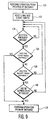
- the receiver controller determines whether the long timer has expired in step 126. If so, the receiver controller performs the operation of the new RF message. If not, the receiver controller checks whether the short timer has expired in step 128. If not, the receiver controller returns to step 124 to detect a new valid RF message. If so, the receiver controller checks whether the keypress status bit has toggled in step 130. If so, the receiver controller performs the operation of the new RF message.
- the receiver controller returns to step 124 to detect a new valid RF message. Therefore, it can be seen that the operation for a new RF message is performed if the long timer has expired or if the short timer has expired and the keypress status bit in the RF message has toggled to indicate a new keypress.
- remote control 10 may be modified to allow the user to program a security code into remote control 10 using a pre-existing remote control programming sequence so that remote control 10 includes the security code in the signal transmissions and the controlled device only accepts control signals which include the proper security code.
- a modification is advantageous in an environment wherein many RF remote control devices are being used because the security code prevents signals from other neighboring remote control devices from interfering with the operation of the controlled device.
- remote control 10 may be configured to transmit one of a plurality of security codes for controlling a designated one of a plurality of electronic devices in the same household.
- one security code may be assigned to a satellite receiver and a different security code may be assigned to a television receiver.
- Any conventionally known method for programming remote control devices may be used to assign the security codes, for example, the user may program the remote control pressing an appropriate device key, for example, TV, VCR or DSS, and then entering a security code, for example a three digit code.
- the user may be guided through the programming sequence by an appropriate user interface, for example, a menu on an On Screen Display.
Applications Claiming Priority (3)
| Application Number | Priority Date | Filing Date | Title |
|---|---|---|---|
| US3679497P | 1997-01-31 | 1997-01-31 | |
| US36794P | 1997-01-31 | ||
| PCT/US1998/001783 WO1998034207A1 (en) | 1997-01-31 | 1998-01-30 | Remote control apparatus and method |
Publications (2)
| Publication Number | Publication Date |
|---|---|
| EP0956549A1 EP0956549A1 (en) | 1999-11-17 |
| EP0956549B1 true EP0956549B1 (en) | 2002-04-10 |
Family
ID=21890690
Family Applications (1)
| Application Number | Title | Priority Date | Filing Date |
|---|---|---|---|
| EP98903840A Expired - Lifetime EP0956549B1 (en) | 1997-01-31 | 1998-01-30 | Remote control apparatus and method |
Country Status (8)
| Country | Link |
|---|---|
| US (1) | US6529556B1 (zh) |
| EP (1) | EP0956549B1 (zh) |
| JP (1) | JP4124825B2 (zh) |
| KR (1) | KR100501404B1 (zh) |
| CN (1) | CN1122953C (zh) |
| AU (1) | AU6050498A (zh) |
| DE (1) | DE69804768T2 (zh) |
| WO (1) | WO1998034207A1 (zh) |
Cited By (1)
| Publication number | Priority date | Publication date | Assignee | Title |
|---|---|---|---|---|
| US8760587B2 (en) | 2010-10-14 | 2014-06-24 | Thomson Licensing | Remote control device for 3D video system |
Families Citing this family (47)
| Publication number | Priority date | Publication date | Assignee | Title |
|---|---|---|---|---|
| JP2001069475A (ja) * | 1999-08-27 | 2001-03-16 | Pioneer Electronic Corp | ケーブルテレビジョンの端末装置 |
| JP2001147766A (ja) * | 1999-11-22 | 2001-05-29 | Nec Gumma Ltd | ワイヤレスキーボード、このワイヤレスキーボードを入力手段とする情報処理装置及び送信レベル切り替え方式 |
| EP1238381A2 (en) * | 1999-12-10 | 2002-09-11 | Scientific-Atlanta Inc. | System and method for sending multiple infrared (ir) data packets using a single keypress |
| US6763195B1 (en) * | 2000-01-13 | 2004-07-13 | Lightpointe Communications, Inc. | Hybrid wireless optical and radio frequency communication link |
| US6747590B1 (en) * | 2001-02-12 | 2004-06-08 | Harold J. Weber | Alternate command signal decoding option for a remotely controlled apparatus |
| US6895252B2 (en) * | 2001-05-10 | 2005-05-17 | Thomson Licensing Sa | Economical extension of the operating distance of an RF remote link accommodating information signals having differing carrier frequencies |
| KR100455920B1 (ko) * | 2001-12-11 | 2004-11-06 | (주)에스디시스템 | 홈 오토메이션의 알에프 수신장치 |
| AU2003220512A1 (en) * | 2002-03-22 | 2003-10-13 | Index Systems, Inc. | Method and system for reverse universal remote control feature |
| US6980137B2 (en) * | 2002-03-22 | 2005-12-27 | Hewlett-Packard Development Company, L.P. | Systems and methods for data conversion |
| US7183941B2 (en) * | 2003-07-30 | 2007-02-27 | Lear Corporation | Bus-based appliance remote control |
| US7039397B2 (en) * | 2003-07-30 | 2006-05-02 | Lear Corporation | User-assisted programmable appliance control |
| US7068181B2 (en) * | 2003-07-30 | 2006-06-27 | Lear Corporation | Programmable appliance remote control |
| US7161466B2 (en) | 2003-07-30 | 2007-01-09 | Lear Corporation | Remote control automatic appliance activation |
| US7269416B2 (en) * | 2003-07-30 | 2007-09-11 | Lear Corporation | Universal vehicle based garage door opener control system and method |
| US20060198637A1 (en) * | 2005-03-02 | 2006-09-07 | George Lin | Non-directional infrared remote-control transmitter for infrared remote control system |
| US20080137715A1 (en) * | 2005-12-06 | 2008-06-12 | The Chamberlain Group, Inc. | Secure spread spectrum-facilitated remote control signaling method and apparatus |
| US20070126552A1 (en) * | 2005-12-06 | 2007-06-07 | The Chamberlain Group, Inc. | Secure spread spectrum-facilitated remote control signaling method and apparatus |
| JP2007166511A (ja) * | 2005-12-16 | 2007-06-28 | Toshiba Corp | リモコン装置及び情報再生装置 |
| US20070267526A1 (en) * | 2006-05-16 | 2007-11-22 | Uhrich Steven M | Remote operated brush chipper with conspicuity light |
| US20080169899A1 (en) * | 2007-01-12 | 2008-07-17 | Lear Corporation | Voice programmable and voice activated vehicle-based appliance remote control |
| KR100890578B1 (ko) * | 2007-07-23 | 2009-03-25 | 경북대학교 산학협력단 | 원격 무선 네트워크 제어 시스템 및 방법 |
| JP4539695B2 (ja) * | 2007-09-04 | 2010-09-08 | ソニー株式会社 | リモートコントロールシステム、電子機器および制御方法 |
| US8411395B2 (en) * | 2007-10-26 | 2013-04-02 | Fuji Electric Co., Ltd. | Spin valve element and method of driving same |
| WO2009109928A2 (en) * | 2008-03-07 | 2009-09-11 | Philips Intellectual Property & Standards Gmbh | Method of controlling a device arrangement |
| US8134454B2 (en) | 2008-03-26 | 2012-03-13 | Computime, Ltd | Receiver module with dual mode capability |
| JP4364290B1 (ja) * | 2008-08-22 | 2009-11-11 | 株式会社東芝 | Av機器及びその制御方法 |
| US20100118209A1 (en) * | 2008-11-11 | 2010-05-13 | Sony Corporation | System and method for power saving via context based communication |
| EP2427874B1 (en) | 2009-05-05 | 2017-08-23 | Philips Lighting Holding B.V. | Transmitting secondary remote control signals |
| CN101923770B (zh) * | 2009-06-11 | 2013-01-09 | 鸿富锦精密工业(深圳)有限公司 | 遥控器及电量提示系统 |
| CN102081838A (zh) * | 2009-11-27 | 2011-06-01 | 康佳集团股份有限公司 | 一种遥控发射装置,接收装置及遥控方法 |
| US8508482B2 (en) * | 2009-11-30 | 2013-08-13 | Neil Van der Byl | Programmable remote control |
| KR20110065987A (ko) * | 2009-12-10 | 2011-06-16 | 삼성전자주식회사 | 리모트 컨트롤 장치 및 그 방법 |
| CN101814233A (zh) * | 2010-04-08 | 2010-08-25 | 郑州炜盛电子科技有限公司 | 红外遥控软件解码方法 |
| US8581672B2 (en) * | 2010-05-14 | 2013-11-12 | Nokia Corporation | Frequency synthesis |
| US10504360B2 (en) * | 2011-04-08 | 2019-12-10 | Ross Gilson | Remote control interference avoidance |
| US8941784B2 (en) * | 2011-09-01 | 2015-01-27 | Echostar Technologies L.L.C. | Easy RF remote control pairing for networked set top boxes |
| US10366299B2 (en) * | 2011-10-25 | 2019-07-30 | Bull Hn Information Systems, Inc. | Sorting/scanning system camera upgrade apparatus with backwards compatibility |
| US9215394B2 (en) * | 2011-10-28 | 2015-12-15 | Universal Electronics Inc. | System and method for optimized appliance control |
| US11295603B2 (en) | 2011-10-28 | 2022-04-05 | Universal Electronics Inc. | System and method for optimized appliance control |
| US9449500B2 (en) | 2012-08-08 | 2016-09-20 | Universal Electronics Inc. | System and method for optimized appliance control |
| US10937308B2 (en) | 2011-10-28 | 2021-03-02 | Universal Electronics Inc. | System and method for optimized appliance control |
| US10593195B2 (en) | 2011-10-28 | 2020-03-17 | Universal Electronics Inc. | System and method for optimized appliance control |
| CN103236149B (zh) * | 2013-05-08 | 2016-03-09 | 广州爱孚圣电子科技有限公司 | 多功能远距离无线点火遥控方法 |
| JP2014225767A (ja) * | 2013-05-16 | 2014-12-04 | 船井電機株式会社 | リモートコントロール装置および電子機器システム |
| US9560407B2 (en) * | 2015-02-26 | 2017-01-31 | Verizon Patent And Licensing Inc. | Systems and methods for managing pairing of remote control devices with a plurality of media content processing devices |
| CN105869383A (zh) * | 2016-04-13 | 2016-08-17 | 北京精益理想科技有限公司 | 红外数据处理方法、红外指令调用方法与系统 |
| US20200204392A1 (en) * | 2018-12-20 | 2020-06-25 | Ming-Tsung Chen | Home appliance control system |
Family Cites Families (4)
| Publication number | Priority date | Publication date | Assignee | Title |
|---|---|---|---|---|
| JPS62186537U (zh) | 1986-05-16 | 1987-11-27 | ||
| JP2829185B2 (ja) | 1992-03-30 | 1998-11-25 | シャープ株式会社 | 信号伝送方法 |
| US5659883A (en) * | 1992-08-24 | 1997-08-19 | General Instrument Corporation | Selection between separately received messages in diverse-frequency remote-control communication system |
| CA2166457C (en) * | 1995-01-04 | 2006-03-21 | Jeffrey Alan Martin | Remote receiver that coordinates command signals from differing sources including radio frequency and infrared sources and setup of same |
-
1998
- 1998-01-30 DE DE69804768T patent/DE69804768T2/de not_active Expired - Lifetime
- 1998-01-30 JP JP53308998A patent/JP4124825B2/ja not_active Expired - Lifetime
- 1998-01-30 US US09/331,996 patent/US6529556B1/en not_active Expired - Lifetime
- 1998-01-30 EP EP98903840A patent/EP0956549B1/en not_active Expired - Lifetime
- 1998-01-30 AU AU60504/98A patent/AU6050498A/en not_active Abandoned
- 1998-01-30 KR KR10-1999-7006134A patent/KR100501404B1/ko not_active IP Right Cessation
- 1998-01-30 WO PCT/US1998/001783 patent/WO1998034207A1/en active IP Right Grant
- 1998-01-30 CN CN98802207A patent/CN1122953C/zh not_active Expired - Lifetime
Cited By (1)
| Publication number | Priority date | Publication date | Assignee | Title |
|---|---|---|---|---|
| US8760587B2 (en) | 2010-10-14 | 2014-06-24 | Thomson Licensing | Remote control device for 3D video system |
Also Published As
| Publication number | Publication date |
|---|---|
| DE69804768D1 (de) | 2002-05-16 |
| KR100501404B1 (ko) | 2005-07-18 |
| EP0956549A1 (en) | 1999-11-17 |
| CN1246193A (zh) | 2000-03-01 |
| US6529556B1 (en) | 2003-03-04 |
| KR20000069921A (ko) | 2000-11-25 |
| DE69804768T2 (de) | 2002-09-12 |
| WO1998034207A1 (en) | 1998-08-06 |
| CN1122953C (zh) | 2003-10-01 |
| JP4124825B2 (ja) | 2008-07-23 |
| AU6050498A (en) | 1998-08-25 |
| JP2001509927A (ja) | 2001-07-24 |
Similar Documents
| Publication | Publication Date | Title |
|---|---|---|
| EP0956549B1 (en) | Remote control apparatus and method | |
| WO1998034207A9 (en) | Remote control apparatus and method | |
| EP0956550B1 (en) | Communications system for remote control systems | |
| US20070133994A1 (en) | Automatic frequency hopping remote controller | |
| US20020187796A1 (en) | Economical extension of the operating distance of an RF remote link accommodating information signals having differing carrier frequencies | |
| KR100853111B1 (ko) | 다른 ir 반송파 주파수들을 갖는 rf 원격 링크 적응 ir 원격 제어들의 동작 거리의 경제적인 확장 | |
| US8942186B2 (en) | Transmission and reception channel selection for communicating between a transmitter unit and a receiver unit | |
| EP1761908B1 (en) | Remote control code filtering used for relaying of remote control codes | |
| US7049995B2 (en) | Method and apparatus for remote control transmission | |
| KR100227433B1 (ko) | 가전제품 중앙집중식 제어장치 | |
| US6597292B1 (en) | Wireless transmission apparatus and control system | |
| MXPA99006974A (en) | Remote control apparatus and method | |
| KR19980059090A (ko) | 양방향 통신이 가능한 제어장치 | |
| JPH08117444A (ja) | ワイヤレスコントローラ | |
| EP1796055A1 (en) | Automatic frequency hopping remote controller | |
| KR20000040643A (ko) | 텔레비젼의 리모콘 수신장치 및 수신방법 | |
| KR19990000746A (ko) | 리모콘 송수신 장치 및 방법 | |
| JPH11220427A (ja) | リモコン受信装置及びリモコンシステム | |
| MXPA99007099A (en) | Communications system for remote control systems | |
| KR19990011712A (ko) | 가전기기의 리모콘 호출 장치 및 방법 | |
| JPH0213019A (ja) | リモートコントロール装置 | |
| EP1238381A2 (en) | System and method for sending multiple infrared (ir) data packets using a single keypress | |
| KR19990020672U (ko) | 위치확인 기능을 갖는 리모콘 시스템 |
Legal Events
| Date | Code | Title | Description |
|---|---|---|---|
| PUAI | Public reference made under article 153(3) epc to a published international application that has entered the european phase |
Free format text: ORIGINAL CODE: 0009012 |
|
| 17P | Request for examination filed |
Effective date: 19990712 |
|
| AK | Designated contracting states |
Kind code of ref document: A1 Designated state(s): DE FR GB IE IT |
|
| 17Q | First examination report despatched |
Effective date: 20000510 |
|
| GRAG | Despatch of communication of intention to grant |
Free format text: ORIGINAL CODE: EPIDOS AGRA |
|
| GRAG | Despatch of communication of intention to grant |
Free format text: ORIGINAL CODE: EPIDOS AGRA |
|
| GRAH | Despatch of communication of intention to grant a patent |
Free format text: ORIGINAL CODE: EPIDOS IGRA |
|
| GRAH | Despatch of communication of intention to grant a patent |
Free format text: ORIGINAL CODE: EPIDOS IGRA |
|
| REG | Reference to a national code |
Ref country code: GB Ref legal event code: IF02 |
|
| GRAA | (expected) grant |
Free format text: ORIGINAL CODE: 0009210 |
|
| AK | Designated contracting states |
Kind code of ref document: B1 Designated state(s): DE FR GB IE IT |
|
| REG | Reference to a national code |
Ref country code: IE Ref legal event code: FG4D |
|
| REF | Corresponds to: |
Ref document number: 69804768 Country of ref document: DE Date of ref document: 20020516 |
|
| ET | Fr: translation filed | ||
| REG | Reference to a national code |
Ref country code: FR Ref legal event code: D6 |
|
| REG | Reference to a national code |
Ref country code: GB Ref legal event code: 746 Effective date: 20030103 |
|
| PG25 | Lapsed in a contracting state [announced via postgrant information from national office to epo] |
Ref country code: IE Free format text: LAPSE BECAUSE OF NON-PAYMENT OF DUE FEES Effective date: 20030130 |
|
| PLBE | No opposition filed within time limit |
Free format text: ORIGINAL CODE: 0009261 |
|
| STAA | Information on the status of an ep patent application or granted ep patent |
Free format text: STATUS: NO OPPOSITION FILED WITHIN TIME LIMIT |
|
| 26N | No opposition filed |
Effective date: 20030113 |
|
| REG | Reference to a national code |
Ref country code: IE Ref legal event code: MM4A |
|
| REG | Reference to a national code |
Ref country code: FR Ref legal event code: PLFP Year of fee payment: 19 |
|
| REG | Reference to a national code |
Ref country code: FR Ref legal event code: PLFP Year of fee payment: 20 |
|
| PGFP | Annual fee paid to national office [announced via postgrant information from national office to epo] |
Ref country code: GB Payment date: 20161222 Year of fee payment: 20 |
|
| PGFP | Annual fee paid to national office [announced via postgrant information from national office to epo] |
Ref country code: FR Payment date: 20170123 Year of fee payment: 20 Ref country code: DE Payment date: 20170125 Year of fee payment: 20 |
|
| PGFP | Annual fee paid to national office [announced via postgrant information from national office to epo] |
Ref country code: IT Payment date: 20170123 Year of fee payment: 20 |
|
| REG | Reference to a national code |
Ref country code: DE Ref legal event code: R082 Ref document number: 69804768 Country of ref document: DE Representative=s name: HOFSTETTER, SCHURACK & PARTNER PATENT- UND REC, DE |
|
| REG | Reference to a national code |
Ref country code: DE Ref legal event code: R071 Ref document number: 69804768 Country of ref document: DE |
|
| REG | Reference to a national code |
Ref country code: GB Ref legal event code: PE20 Expiry date: 20180129 |
|
| PG25 | Lapsed in a contracting state [announced via postgrant information from national office to epo] |
Ref country code: GB Free format text: LAPSE BECAUSE OF EXPIRATION OF PROTECTION Effective date: 20180129 |