EP0956189B1 - Procede de fabrication de produits en polytetrafluorethylene expanse - Google Patents
Procede de fabrication de produits en polytetrafluorethylene expanse Download PDFInfo
- Publication number
- EP0956189B1 EP0956189B1 EP98908467A EP98908467A EP0956189B1 EP 0956189 B1 EP0956189 B1 EP 0956189B1 EP 98908467 A EP98908467 A EP 98908467A EP 98908467 A EP98908467 A EP 98908467A EP 0956189 B1 EP0956189 B1 EP 0956189B1
- Authority
- EP
- European Patent Office
- Prior art keywords
- tubular extrudate
- shaping
- tubular
- shaping mandrel
- eptfe
- Prior art date
- Legal status (The legal status is an assumption and is not a legal conclusion. Google has not performed a legal analysis and makes no representation as to the accuracy of the status listed.)
- Expired - Lifetime
Links
Images


Classifications
-
- A—HUMAN NECESSITIES
- A61—MEDICAL OR VETERINARY SCIENCE; HYGIENE
- A61F—FILTERS IMPLANTABLE INTO BLOOD VESSELS; PROSTHESES; DEVICES PROVIDING PATENCY TO, OR PREVENTING COLLAPSING OF, TUBULAR STRUCTURES OF THE BODY, e.g. STENTS; ORTHOPAEDIC, NURSING OR CONTRACEPTIVE DEVICES; FOMENTATION; TREATMENT OR PROTECTION OF EYES OR EARS; BANDAGES, DRESSINGS OR ABSORBENT PADS; FIRST-AID KITS
- A61F2/00—Filters implantable into blood vessels; Prostheses, i.e. artificial substitutes or replacements for parts of the body; Appliances for connecting them with the body; Devices providing patency to, or preventing collapsing of, tubular structures of the body, e.g. stents
- A61F2/02—Prostheses implantable into the body
- A61F2/04—Hollow or tubular parts of organs, e.g. bladders, tracheae, bronchi or bile ducts
- A61F2/06—Blood vessels
-
- B—PERFORMING OPERATIONS; TRANSPORTING
- B29—WORKING OF PLASTICS; WORKING OF SUBSTANCES IN A PLASTIC STATE IN GENERAL
- B29C—SHAPING OR JOINING OF PLASTICS; SHAPING OF MATERIAL IN A PLASTIC STATE, NOT OTHERWISE PROVIDED FOR; AFTER-TREATMENT OF THE SHAPED PRODUCTS, e.g. REPAIRING
- B29C55/00—Shaping by stretching, e.g. drawing through a die; Apparatus therefor
- B29C55/22—Shaping by stretching, e.g. drawing through a die; Apparatus therefor of tubes
- B29C55/26—Shaping by stretching, e.g. drawing through a die; Apparatus therefor of tubes biaxial
-
- B—PERFORMING OPERATIONS; TRANSPORTING
- B29—WORKING OF PLASTICS; WORKING OF SUBSTANCES IN A PLASTIC STATE IN GENERAL
- B29C—SHAPING OR JOINING OF PLASTICS; SHAPING OF MATERIAL IN A PLASTIC STATE, NOT OTHERWISE PROVIDED FOR; AFTER-TREATMENT OF THE SHAPED PRODUCTS, e.g. REPAIRING
- B29C61/00—Shaping by liberation of internal stresses; Making preforms having internal stresses; Apparatus therefor
- B29C61/02—Thermal shrinking
- B29C61/025—Thermal shrinking for the production of hollow or tubular articles
-
- A—HUMAN NECESSITIES
- A61—MEDICAL OR VETERINARY SCIENCE; HYGIENE
- A61F—FILTERS IMPLANTABLE INTO BLOOD VESSELS; PROSTHESES; DEVICES PROVIDING PATENCY TO, OR PREVENTING COLLAPSING OF, TUBULAR STRUCTURES OF THE BODY, e.g. STENTS; ORTHOPAEDIC, NURSING OR CONTRACEPTIVE DEVICES; FOMENTATION; TREATMENT OR PROTECTION OF EYES OR EARS; BANDAGES, DRESSINGS OR ABSORBENT PADS; FIRST-AID KITS
- A61F2/00—Filters implantable into blood vessels; Prostheses, i.e. artificial substitutes or replacements for parts of the body; Appliances for connecting them with the body; Devices providing patency to, or preventing collapsing of, tubular structures of the body, e.g. stents
- A61F2/02—Prostheses implantable into the body
- A61F2/04—Hollow or tubular parts of organs, e.g. bladders, tracheae, bronchi or bile ducts
- A61F2/06—Blood vessels
- A61F2/07—Stent-grafts
-
- A—HUMAN NECESSITIES
- A61—MEDICAL OR VETERINARY SCIENCE; HYGIENE
- A61F—FILTERS IMPLANTABLE INTO BLOOD VESSELS; PROSTHESES; DEVICES PROVIDING PATENCY TO, OR PREVENTING COLLAPSING OF, TUBULAR STRUCTURES OF THE BODY, e.g. STENTS; ORTHOPAEDIC, NURSING OR CONTRACEPTIVE DEVICES; FOMENTATION; TREATMENT OR PROTECTION OF EYES OR EARS; BANDAGES, DRESSINGS OR ABSORBENT PADS; FIRST-AID KITS
- A61F2/00—Filters implantable into blood vessels; Prostheses, i.e. artificial substitutes or replacements for parts of the body; Appliances for connecting them with the body; Devices providing patency to, or preventing collapsing of, tubular structures of the body, e.g. stents
- A61F2/02—Prostheses implantable into the body
- A61F2/04—Hollow or tubular parts of organs, e.g. bladders, tracheae, bronchi or bile ducts
- A61F2/06—Blood vessels
- A61F2002/061—Blood vessels provided with means for allowing access to secondary lumens
-
- A—HUMAN NECESSITIES
- A61—MEDICAL OR VETERINARY SCIENCE; HYGIENE
- A61F—FILTERS IMPLANTABLE INTO BLOOD VESSELS; PROSTHESES; DEVICES PROVIDING PATENCY TO, OR PREVENTING COLLAPSING OF, TUBULAR STRUCTURES OF THE BODY, e.g. STENTS; ORTHOPAEDIC, NURSING OR CONTRACEPTIVE DEVICES; FOMENTATION; TREATMENT OR PROTECTION OF EYES OR EARS; BANDAGES, DRESSINGS OR ABSORBENT PADS; FIRST-AID KITS
- A61F2/00—Filters implantable into blood vessels; Prostheses, i.e. artificial substitutes or replacements for parts of the body; Appliances for connecting them with the body; Devices providing patency to, or preventing collapsing of, tubular structures of the body, e.g. stents
- A61F2/02—Prostheses implantable into the body
- A61F2/04—Hollow or tubular parts of organs, e.g. bladders, tracheae, bronchi or bile ducts
- A61F2/06—Blood vessels
- A61F2002/065—Y-shaped blood vessels
-
- A—HUMAN NECESSITIES
- A61—MEDICAL OR VETERINARY SCIENCE; HYGIENE
- A61F—FILTERS IMPLANTABLE INTO BLOOD VESSELS; PROSTHESES; DEVICES PROVIDING PATENCY TO, OR PREVENTING COLLAPSING OF, TUBULAR STRUCTURES OF THE BODY, e.g. STENTS; ORTHOPAEDIC, NURSING OR CONTRACEPTIVE DEVICES; FOMENTATION; TREATMENT OR PROTECTION OF EYES OR EARS; BANDAGES, DRESSINGS OR ABSORBENT PADS; FIRST-AID KITS
- A61F2/00—Filters implantable into blood vessels; Prostheses, i.e. artificial substitutes or replacements for parts of the body; Appliances for connecting them with the body; Devices providing patency to, or preventing collapsing of, tubular structures of the body, e.g. stents
- A61F2/02—Prostheses implantable into the body
- A61F2/04—Hollow or tubular parts of organs, e.g. bladders, tracheae, bronchi or bile ducts
- A61F2/06—Blood vessels
- A61F2/07—Stent-grafts
- A61F2002/075—Stent-grafts the stent being loosely attached to the graft material, e.g. by stitching
-
- B—PERFORMING OPERATIONS; TRANSPORTING
- B29—WORKING OF PLASTICS; WORKING OF SUBSTANCES IN A PLASTIC STATE IN GENERAL
- B29K—INDEXING SCHEME ASSOCIATED WITH SUBCLASSES B29B, B29C OR B29D, RELATING TO MOULDING MATERIALS OR TO MATERIALS FOR MOULDS, REINFORCEMENTS, FILLERS OR PREFORMED PARTS, e.g. INSERTS
- B29K2027/00—Use of polyvinylhalogenides or derivatives thereof as moulding material
- B29K2027/12—Use of polyvinylhalogenides or derivatives thereof as moulding material containing fluorine
- B29K2027/18—PTFE, i.e. polytetrafluorethene, e.g. ePTFE, i.e. expanded polytetrafluorethene
-
- B—PERFORMING OPERATIONS; TRANSPORTING
- B29—WORKING OF PLASTICS; WORKING OF SUBSTANCES IN A PLASTIC STATE IN GENERAL
- B29L—INDEXING SCHEME ASSOCIATED WITH SUBCLASS B29C, RELATING TO PARTICULAR ARTICLES
- B29L2031/00—Other particular articles
- B29L2031/753—Medical equipment; Accessories therefor
- B29L2031/7532—Artificial members, protheses
- B29L2031/7534—Cardiovascular protheses
Definitions
- the present invention relates generally to methods of making shaped three-dimensional products from microporous expanded polytetrafluoroethylene. More particularly, the present invention relates to a method of shaping three-dimensional products by manipulating an expanded polytetrafluoroethylene tubular body into a desired three-dimensional conformation.
- the present invention entails radially expanding a longitudinally expanded polytetrafluoroethylene (ePTFE) tube to form a radially expanded ePTFE (rePTFE) tube, engaging the rePTFE tube circumferentially about a shaping mandrel, heating the assembly to a temperature below the crystalline melt point temperature, or sintering temperature, of polytetrafluoroethylene to radially shrink the diameter of the rePTFE tube into intimate contact with the shaping mandrel, and heating the assembly to a temperature above the crystalline melt point temperature of polytetrafluoroethylene to amorphously lock the microstructure of the shaped polytetrafluoroethylene body.
- ePTFE longitudinally expanded polytetrafluoroethylene
- rePTFE radially expanded ePTFE
- US-A-4957669 discloses shaping PTFE Vascular tubing on a mandrel.
- the two part form of claim 1 below corresponds to this prior disclosure.
- the three-dimensional shaped microporous expanded polytetrafluoroethylene products made in accordance with the method of the present invention are particularly well suited for use as medical implants, and are particularly useful as venous or arterial prostheses either as vein or artery replacements, as endovascular liners, arterio-venous shunts, or as venous access grafts.
- shaped microporous expanded polytetrafluoroethylene grafts have been made which have a flanged cuff section contiguous with an elongate tubular section.
- the cuffed prosthesis are particularly well suited for use in end-to-side anastomoses such as that required in femoro-popliteal bypass procedures where the flanged cuff section is sutured about an open arteriotomy to form the end-to-side anastomosis.
- the shaped expanded polytetrafluoroethylene products may be configured to have a taper along its longitudinal axis, with a proximal end having either a larger or smaller inner diameter than the distal end, or may have a step taper, where there is a tapered transition zone between two different inner diameter sections, or the product may be configured to have an intermediate section of a larger diameter than proximal or distal ends of the product, or the product may be configured into a bifurcated or trifurcated graft where each of the legs is formed from appropriately sized appendage sections of a base tubular graft member.
- Tu, et al. U.S. Patent No. 5,061,276 issued October 29, 1991 is similar to the '399 Tu, et al. patent but discloses a graft which is made entirely of a PTFE elastomer solution admixture having inner surface distances of 25 microns and outer surface internodal distances of approximately 90 microns.
- Yamamoto, et al. U.S. Patent No. 4,830,062 issued May 16, 1989 disclose radial expansion of tetrafluoroethylene tubes to impart porosity in the tube and the resulting heat shrinkability of the radial expanded tetrafluoroethylene tube.
- This patent does not disclose either the radial expandability of longitudinally expanded ePTFE or the heat shrinkable nature of radial expanded ePTFE.
- This method radially expands the PTFE material using the heat and ultrasonic energy as the motive force for expansion. Because the method heats the ePTFE material as it is being urged into conformation with the tapered shape of the ultrasonic horn, the ePTFE microstructure is compromised. Moreover, because of the need for the ultrasonic horn, the conformational shapes which may be formed are limited to simple regular shapes which are capable of easy removal from the ultrasonic horn without compromising the integrity of the ePTFE material.
- the present invention offers an alternative approach to forming complex conformations for endoprostheses from ePTFE in which an ePTFE tube is radially expanded to a diameter which is relatively greater than the unexpanded diameter of the ePTFE tube, the radially expanded ePTFE tube is engaged about a shaping mold, then heated which causes the radially expanded ePTFE tube to radially contract about the shaping mold, thereby forming to the external configuration of the shaping mold.
- Highly constrained regions, or highly tortuous regions may require external wrapping in order to ensure close conformation with the shaping mold.
- the shaped ePTFE material has its internal surface in intimate contact with the shaping mold.
- PTFE resin 12 preferably a high molecular weight resin such as that sold under the trademark CD 123 (ICI Chemical Company)
- an extrusion aid lubricant 14 preferably a mineral spirits solvent, such as that sold under the trademark ISOPAR M (Exxon Chemical Co.).
- the lubricant be present in an amount between 15- 30 wt. % of the PTFE resin, preferably between 18 and 25 wt. %.
- the weight percent of lubricant to PTFE resin is referred to as the "lubricant level" or "lube level.”
- the admixture of PTFE resin and lubricant is then preformed into an extrusion billet at step 16.
- the extrusion billet is then extruded in a ram extruder to form tubular extrudates at step 18.
- the tubular extrudates are then dried at step 20 to evaporate at least a substantial quantity of lubricant present in the extrudate and then longitudinally expanded at step 22. Longitudinal expansion of the dried tubular extrudates imparts the node and fibril microstructure characteristic of ePTFE as taught by U.S.
- Patents 3,953,566, 4,187,390 and 4,482,516, which are hereby expressly incorporated by reference for their teaching of methods of making ePTFE tubes and films.
- the dried tubular extrudates are then placed into a sintering oven, while restraining the ends against longitudinal shortening, and at least partially sintered.
- the term "sintered” is intended to refer to the ratio of relative amorphous content of heat treated ePTFE as measured by differential scanning calorimetry wherein the amorphous content is at least 10%.
- Differential scanning calorimetry is a thermo analytical method which effectively measures the difference in temperature between the sample and a reference material while both are heated simultaneously by measuring a quantum of additional heat required to maintain the sample and the reference material at a zero temperature differential.
- a temperature difference signal is generated when there is a ⁇ T between the sample and reference.
- the temperature difference signal is fed into a signal amplifier which drives a separate heater which supplies additional heat equal to the ⁇ T value.
- the DSC then measures the heat input in millicalories per second.
- the sample When the sample reaches a temperature at which an endothermic process, such as a solid-solid transition, e.g., phase change from crystalline to amorphous structure, occurs, the sample will not be heated as rapidly as the reference and a temperature difference appears. Conversely, when a sample reaches a temperature at which an exothermic process occurs, e.g. , crystallization, the sample will gain in temperature relative to the reference and a temperature difference will appear. After the onset of each temperature differential, the base line will again approach zero after the process is complete, and subsequent exothermic or endothermic events may be observed as the sample and reference are heated.
- an endothermic process such as a solid-solid transition, e.g., phase change from crystalline to amorphous structure
- the terms "partially sintered” or “semi-sintered” are intended to mean that the PTFE material has a crystalline conversion value between about 0.10 and 0.85, preferably 0.20 to 0.75
- DSC differential scanning calorimetry
- a tubular ePTFE member 48 which is at least partially sintered, is co-axially engaged about a dilatation catheter 44 having an inflation balloon 46 carried thereupon.
- the dilatation catheter 44, inflation balloon 46 and tubular ePTFE member 48 are introduced into a constraining chamber 42.
- the constraining chamber 42 has a generally tubular configuration, having a circular transverse cross-sectional shape, and has an inner diameter which is approximately 200 to 400 % greater than the outer diameter of the tubular ePTFE member 48.
- the constraining chamber 42 is preferably made of any suitable material which is capable of safely withstanding applied radially directed pressures in excess of the burst pressure of the inflation balloon 46. It has been found that a plastic marketed under the trademark LEXAN by DuPont de Nemours is particularly well suited to this application due to its strength and transparency.
- the tubular ePTFE member 48, inflation balloon 46, and dilatation catheter 44 are introduced into the constraining chamber 42 such that the constraining chamber 42 resides concentrically about the tubular ePTFE member 48.
- a positive pressure is applied through the dilatation catheter 44 and into the inflation balloon 46 which imparts a radially directed force against the lumenal surface of the tubular ePTFE member.
- radiopaque saline, Ringers solution or distilled water which is pumped, via a manually or mechanically actuated syringe, through the dilatation catheter 44 and into the inflation balloon 46 as the pressure source.
- the at least partially sintered tubular ePTFE member 48 will radially expand under the influence of the radially outwardly directed fluid pressure being exerted through the inflation balloon 46 until it is in intimate contact with and conforms to the inner surface 43 of the constraining chamber 42.
- various configurations of the inner surface 43 of the constraining chamber 42 may be employed to impart a radially expanded shape to the tubular ePTFE member 48.
- Examples of such alternative dimensional configurations for the constraining chamber 42 include regular shapes such as frustroconical, stepped, or step tapered or irregular shapes, such as bell shaped or horn shaped.
- the inner surface 43 of the constraining chamber 42 may have a surface configuration which includes patterns or discontinuities, such as corrugations, recesses or protrusions which will impress a pattern or discontinuity upon the outer surface of the tubular ePTFE member 48 as it is radially expanded into intimate contact with the inner surface 43 of the constraining chamber 42.
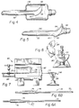
- a shaping mandrel 50 such as that used to make the inventive flanged graft for end-to-side anastomosis disclosed in co-pending PCT International Application Serial No. PCT/US96/02715, filed February 28, 1996, entitled “Apparatus and Method for Making Flanged End-to-Side Anastomosis," is illustrated in Figure 3.
- Shaping mandrel 50 includes a generally cylindrical body section 52 and a radially flared end section 56.
- the radially flared end section 56 has a bell-like shape and is angularly displaced from the longitudinal axis 51 of the shaping mandrel 50.
- the radially flared end section 56 preferably has a toe section 58 which is angularly displaced from the longitudinal axis 51 of the shaping mandrel 50 by an angle ⁇ which is greater than 90° and less than 180° displaced from the longitudinal axis 51 of the shaping mandrel 50.
- the radially flared end section 56 also preferably has a heel section 60 which is angularly displaced from the longitudinal axis 51 of the shaping mandrel by an angle ⁇ which is less than 90° and greater than 0° displaced from the longitudinal axis 51 of the shaping mandrel 50.
- the angles ⁇ and ⁇ are measured between the longitudinal axis 51 and a line 55 extending from an outer surface of toe section 58 through the longitudinal axis 51 to the heel section 60.
- Figure 4 depicts engagement of the shaping mandrel 50 concentrically within the radially expanded ePTFE 48 and covering at least a portion of the cylindrical body section 52 and the entire radially flared end section 56, including the toe section 56 and the heel section 60 of the shaping mandrel.
- the flared end section 56 has a heel region 60 having an angle ⁇ which is less than or equal to 45°, to provide an external wrap of polytetrafluoroethylene tape, for example PTFE or TEFLON tape, helically wrapped about the shaping mandrel 50, particularly the flared end section 56 and tensioned thereabout to confine the ePTFE member 48 to the geometry of the flared end section 56.
- polytetrafluoroethylene tape for example PTFE or TEFLON tape
- FIGS 6A and 6B depict an alternative embodiment of the shaping mandrel 70 as having an elongate shaft 72 passing along and defining the longitudinal axis of the shaping mandrel 70.
- the elongate shaft 72 has a transverse cross-sectional diameter which corresponds to the diameter of the non-flared section of the ePTFE end product desired.
- a generally cylindrical shaping body 74 is provided at a point along the longitudinal axis of the elongate shaft 72 and has a diameter larger than the elongate shaft 72 and corresponding to the desired final diameter of the end product.
- the cylindrical shaping body 74 has a beveled end section 76 which subtends an angle ⁇ relative to the longitudinal axis of the shaping mandrel 70.
- Angle ⁇ may assume any desired angular displacement from the longitudinal axis between a value greater than 0 and less than 90, but is preferably between 25° and 45°.
- the shaping mandrel 50 it is preferable to make the shaping mandrel 70 of a material which is compatible with ePTFE and is suitable for use in manufacturing implantable medical devices, e.g. , stainless steel.
- FIGS 7 and 8 depict a heating assembly 80 for inducing radial contraction of the ePTFE member 42 into intimate contact with the configuration of the shaping mandrel 70, specifically the elongate shaft 72 and the cylindrical shaping body 74.
- the heating assembly consists generally of a clam-shell oven 82 having an electrical induction heating element and ceramic insulation and openings on each opposing lateral end to permit the elongate shaft 72 to pass laterally through the clam-shell oven 82 while exposing the cylindrical shaping body 74 and the portion of the ePTFE member 42 to the heating elements within the clam-shell oven 82.
- Clamping members 85 and 86 are preferably provided adjacent each opposing lateral end of the clam-shell oven 82 to secure sections of the elongate shaft 72 which project from the clam-shell oven 82.
- the step of radially expanding the ePTFE tubular member 26 be carried out at a temperature approximating human body temperature, i.e., be between about 35 - 45°C. This may be accomplished by radially expanding in heated air or in a heated water bath.
- the heat shrink step 32 be performed at a temperature above the first crystalline melt point of PTFE, but below the second crystalline melt point of PTFE, preferably between 327 to 340°C and that the ePTFE tubular member and the shaping mandrel be subject to heating for between 5 minutes and 10 minutes dwell time in the heating oven, preferably for about 8 minutes.
- the ePTFE tubular member prior to heating the ePTFE tubular member during the heat shrink step 32, it is desirable to tightly wrap the ePTFE tubular member about the flared or tapered end section of the shaping mandrel 50, loosely wrap the ePTFE tubular member which is on the elongate shaft of the shaping mandrel and then clamp the ePTFE tubular member sections which project outside the oven to guard against longitudinal contraction during heating.
- tubular ePTFE articles may be made by the method of the present invention.
- the present invention may be adapted to produce a wide variety of tubular medical prosthetic devices.
- Figure 9 depicts a branched vascular graft 100 which consists of an ePTFE tubular body 102 and has a plurality of smaller branch conduits 103 and 104 projecting laterally outward from the tubular body 102.
- the branch conduits 103 and 104 are positioned about the circumference of the tubular body 102 at a position which is anatomically matched with a patient's corresponding branch conduits.
- the plurality of branch conduits 103 and 104 may be positioned to correspond to the anatomic position of the patient's renal arteries to the endogenous renal arteries may be anastomosed to the branch conduits 103 and 104 projecting from the tubular body 102.
- Figure 10 illustrates an endoluminal stent-graft device which is an endoluminal stent, such as a PALMAZ stent (Johnson & Johnson Interventional Systems, Inc. Warren, New Jersey), a GIANTURCO stent (Cook Medical Corp., Indianapolis, Indiana), a WALLSTENT (Schneider, USA), or a NITINOL stent is substituted from the shaping mandrel and the radially expanded ePTFE tubular member 112 is radially contracted about the stent 114.
- Figure 10 does not show any flange in accordance with the invention claimed herein.
- Figure 11 illustrates a prosthetic aortic arch 120 consisting of an ePTFE aortic prosthesis 122 having a central lumen 123 and a plurality of branch arterial prosthetic limbs 124, 126 projecting outwardly from the crest of the aortic arch prosthesis 122.
- the ePTFE aortic prosthesis is fashioned in accordance with the above-described inventive method, except that the shaping mandrel is configured in a C-shape and has a plurality of projections emanating from a position along the length of the shaping mandrel which form the branch arterial prosthetic limbs 124, 126 when the radially expanded ePTFE is radially contracted about the shaping mandrel.
- a bifurcated graft 130 may be formed in accordance with the above-described inventive method.
- the inventive bifurcated graft 130 consists of a Y-shaped tubular member having a main body portion 132 and a main lumen 131 open to a proximal end of the main body portion 132.
- the main body portion 132 is bifurcated at a distal end thereof into a plurality of bifurcated tubular members 134, 136, each of the plurality of bifurcated tubular members 134, 136 has an associated bifurcated lumen 135, 137 therein.
- the bifurcated lumina 135, 137 communicate with the main lumen 131 to conduct a fluid flow, such as blood, through the main lumen 131 and into and through the bifurcated lumina 135, 137.
- a fluid flow such as blood
- the bifurcated graft 130 is not limited to having two bifurcated lumina 135, 137, but may include more than two bifurcations to correspond with a branched anatomical structure having more than two bifurcations.
- the bifurcated graft 130 may be made in accordance with the present invention utilizing the shaping mandrel 140 and crimping member 144 illustrated in Figure 12B.
- a partially sintered ePTFE tubular member 142 is radially expanded as described above.
- a Y-shaped shaping mandrel consisting of a cylindrical main body portion 146 and a plurality of bifurcated leg sections 148, 149 which project from one end of the cylindrical main body portion 146 and are angularly displaced away the longitudinal axis of the shaping member.
- At least one of the bifurcated leg sections 148, 149 be removably coupled to the cylindrical main body portion 146, such as by a threaded coupling 150, to facilitate removal of the shaping mandrel from the finished bifurcated graft 130.
- the radially expanded ePTFE tubular member 142 is engaged concentrically about the Y-shaped shaping mandrel as described above.
- a crimping member 144 consisting of a pair of generally triangular head members 145, 147 which are co-planar with and superimposable upon one another.
- a handle member 151 projects outwardly from each of the generally triangular head members 145, 147 and forms a junction at an end opposing the triangular head members 147, 149 (not shown) which permits the crimping member 144 to function in a tong-like or forceps-like manner.
- either the handle member 151 or the generally triangular head members 145, 147 have a means for applying a positive pressure between the generally triangular head members 147, 149 such that opposing planar surfaces of the generally triangular head members 147, 149 are capable of being brought into intimate contact with one another or into intimate contact with a planar surface interposed between the generally triangular head members 147, 149.
- the crimping member 144 is applied over a webbed section of radially expanded ePTFE which subtends the bifurcation of the shaping mandrel 148 and the ePTFE unsupported between the bifurcated leg members 148, 149 is crimped between and in intimate contact with the opposing generally triangular shaped head members 145, 147.
- a positive pressure is applied to the generally triangular shaped head members 145, 147 to cause the adjacent ePTFE surfaces to come into intimate contact with one another under pressure.
- the entire assembly is then heated to a temperature below the second crystalline melt point of PTFE to cause the ePTFE to radially contract over and assume the shape of the shaping mandrel 140. It will be appreciated that by engaging the ePTFE subtending the space between the bifurcated leg members 148, 149, generally tubular leg sections 155, 157 in the ePTFE are formed.
- the entire assembly including the ePTFE 142, the shaping mandrel 140 and the crimping member 144 are then wrapped with PTFE tape to secure the contracted ePTFE onto the shaping mandrel and secure the crimping member 144 in its position relative to the shaping mandrel 140.
- the wrapped assembly is then introduced into the sintering oven to sinter the ePTFE. After removal from the sintering oven, the assembly is allowed to cool.
- the PTFE tape is removed from the assembly, and at least one of the bifurcated leg sections 148, 149 are decoupled from the main body portion 146 of the shaping mandrel and crimping member 144 is removed from the sintered ePTFE shaped graft 142.
- the sintered ePTFE shaped graft 142 is removed from the shaping mandrel 140 and the ePTFE web subtending the space between the tubular leg sections 155, 157 of the ePTFE graft is trimmed away leaving a seam formed by overlapping and joined sections of the ePTFE tubular member 142.
Landscapes
- Health & Medical Sciences (AREA)
- Engineering & Computer Science (AREA)
- Heart & Thoracic Surgery (AREA)
- Gastroenterology & Hepatology (AREA)
- Life Sciences & Earth Sciences (AREA)
- Manufacturing & Machinery (AREA)
- Animal Behavior & Ethology (AREA)
- Pulmonology (AREA)
- Cardiology (AREA)
- General Health & Medical Sciences (AREA)
- Transplantation (AREA)
- Biomedical Technology (AREA)
- Mechanical Engineering (AREA)
- Vascular Medicine (AREA)
- Thermal Sciences (AREA)
- Physics & Mathematics (AREA)
- Oral & Maxillofacial Surgery (AREA)
- Public Health (AREA)
- Veterinary Medicine (AREA)
- Prostheses (AREA)
- Materials For Medical Uses (AREA)
- Manufacture Of Porous Articles, And Recovery And Treatment Of Waste Products (AREA)
- Extrusion Moulding Of Plastics Or The Like (AREA)
- Shaping By String And By Release Of Stress In Plastics And The Like (AREA)
- Processing And Handling Of Plastics And Other Materials For Molding In General (AREA)
- Molding Of Porous Articles (AREA)
- Treatments Of Macromolecular Shaped Articles (AREA)
Claims (5)
- Procédé de façonnage de tubes en polytétrafluoréthylène expansé pour en faire un objet façonné en trois dimensions, comprenant les étapes qui consistent à :(a) extruder un mélange de résine de polytétrafluoréthylène et de lubrifiant pour en faire un extrudat tubulaire ;(b) sécher l'extrudat tubulaire en éliminant au moins une majeure partie du lubrifiant ;(c) réaliser une expansion longitudinale de l'extrudat tubulaire pour lui conférer une microstructure de polytétrafluoréthylène présentant une pluralité de nodes interconnectés par des fibrilles ;(d) fritter au moins partiellement l'extrudat tubulaire longitudinalement expansé pour conférer une stabilité dimensionnelle à l'extrudat tubulaire supérieure à celle de l'extrudat tubulaire non fritté ;(e) réaliser une expansion radiale de l'extrudat tubulaire au moins partiellement fritté pour lui donner un diamètre supérieur à celui de l'extrudat tubulaire,(f) appliquer l'extrudat tubulaire radialement expansé au moins partiellement fritté sur la circonférence d'un mandrin de façonnage, le mandrin de façonnage présentant une conformation en trois dimensions ; et(g) chauffer le mandrin de façonnage et l'extrudat tubulaire au moins partiellement fritté en vue de rétracter l'extrudat tubulaire partiellement fritté pour le mettre en contact étroit avec le mandrin de façonnage, façonnant ainsi l'extrudat tubulaire partiellement fritté autour du mandrin de façonnage ; ce procédé étant caractérisé en ce que(h) le mandrin de façonnage comprend une section façonnée pour créer une bride sur l'objet en cours de façonnage.
- Procédé selon la revendication 1, dans lequel l'étape de séchage et de frittage au moins partiel de l'extrudat tubulaire comprend, en outre, l'étape de frittage complet de l'extrudat tubulaire de telle sorte que l'extrudat ait une valeur de conversion cristalline de 1.
- Procédé selon la revendication 1, dans lequel l'étape de frittage au moins partiel de l'extrudat tubulaire comprend, en outre, l'étape de chauffage de l'extrudat tubulaire à une température supérieure au point de cristallisation par fusion du PTFE pendant une durée permettant de fritter partiellement l'extrudat tubulaire afin qu'il possède une valeur de conversion cristalline comprise entre 0,10 et 0,85.
- Procédé selon la revendication 3, comprenant en outre l'étape de frittage complet de l'extrudat tubulaire partiellement fritté après l'étape de rétraction de l'extrudat tubulaire pour le mettre en contact étroit avec le mandrin de façonnage.
- Procédé selon la revendication 1, dans lequel l'étape de chauffage comprend, en outre, l'étape qui consiste à exposer le mandrin de façonnage et l'extrudat tubulaire au moins partiellement fritté à une température inférieure au point de cristallisation par fusion du polytétrafluoréthylène et supérieure à une température ambiante à laquelle est mise en oeuvre l'étape d'expansion radiale.
Priority Applications (2)
| Application Number | Priority Date | Filing Date | Title |
|---|---|---|---|
| EP10181987.8A EP2298537A3 (fr) | 1997-02-03 | 1998-02-02 | Procédé pour fabriquer des produits en polytétrafluoroéthylène expansé |
| EP06019043A EP1741544B1 (fr) | 1997-02-03 | 1998-02-02 | Procédé pour fabriquer des produits en polytetrafluoroethylene expanse |
Applications Claiming Priority (3)
| Application Number | Priority Date | Filing Date | Title |
|---|---|---|---|
| US08/792,780 US6203735B1 (en) | 1997-02-03 | 1997-02-03 | Method of making expanded polytetrafluoroethylene products |
| US792780 | 1997-02-03 | ||
| PCT/US1998/002142 WO1998033638A1 (fr) | 1997-02-03 | 1998-02-02 | Procede de fabrication de produits en polytetrafluorethylene expanse |
Related Child Applications (2)
| Application Number | Title | Priority Date | Filing Date |
|---|---|---|---|
| EP10181987.8A Division EP2298537A3 (fr) | 1997-02-03 | 1998-02-02 | Procédé pour fabriquer des produits en polytétrafluoroéthylène expansé |
| EP06019043A Division EP1741544B1 (fr) | 1997-02-03 | 1998-02-02 | Procédé pour fabriquer des produits en polytetrafluoroethylene expanse |
Publications (2)
| Publication Number | Publication Date |
|---|---|
| EP0956189A1 EP0956189A1 (fr) | 1999-11-17 |
| EP0956189B1 true EP0956189B1 (fr) | 2006-11-02 |
Family
ID=25158035
Family Applications (3)
| Application Number | Title | Priority Date | Filing Date |
|---|---|---|---|
| EP06019043A Expired - Lifetime EP1741544B1 (fr) | 1997-02-03 | 1998-02-02 | Procédé pour fabriquer des produits en polytetrafluoroethylene expanse |
| EP10181987.8A Withdrawn EP2298537A3 (fr) | 1997-02-03 | 1998-02-02 | Procédé pour fabriquer des produits en polytétrafluoroéthylène expansé |
| EP98908467A Expired - Lifetime EP0956189B1 (fr) | 1997-02-03 | 1998-02-02 | Procede de fabrication de produits en polytetrafluorethylene expanse |
Family Applications Before (2)
| Application Number | Title | Priority Date | Filing Date |
|---|---|---|---|
| EP06019043A Expired - Lifetime EP1741544B1 (fr) | 1997-02-03 | 1998-02-02 | Procédé pour fabriquer des produits en polytetrafluoroethylene expanse |
| EP10181987.8A Withdrawn EP2298537A3 (fr) | 1997-02-03 | 1998-02-02 | Procédé pour fabriquer des produits en polytétrafluoroéthylène expansé |
Country Status (8)
| Country | Link |
|---|---|
| US (1) | US6203735B1 (fr) |
| EP (3) | EP1741544B1 (fr) |
| JP (1) | JP4255136B2 (fr) |
| AT (1) | ATE344128T1 (fr) |
| AU (1) | AU721661B2 (fr) |
| CA (1) | CA2274694A1 (fr) |
| DE (1) | DE69836316T2 (fr) |
| WO (1) | WO1998033638A1 (fr) |
Cited By (1)
| Publication number | Priority date | Publication date | Assignee | Title |
|---|---|---|---|---|
| US8728151B2 (en) | 2007-12-17 | 2014-05-20 | Aesculap Ag | Woven textile vascular prosthesis |
Families Citing this family (92)
| Publication number | Priority date | Publication date | Assignee | Title |
|---|---|---|---|---|
| ATE287678T1 (de) | 1996-02-28 | 2005-02-15 | Bard Peripheral Vascular Inc | Mit einem flansch ausgestattetes transplantat für eine end-zu-seit-anastomose |
| US6951572B1 (en) * | 1997-02-20 | 2005-10-04 | Endologix, Inc. | Bifurcated vascular graft and method and apparatus for deploying same |
| GB9709967D0 (en) * | 1997-05-17 | 1997-07-09 | Harris Peter L | Prosthetic grafts |
| US6187036B1 (en) | 1998-12-11 | 2001-02-13 | Endologix, Inc. | Endoluminal vascular prosthesis |
| US6733523B2 (en) * | 1998-12-11 | 2004-05-11 | Endologix, Inc. | Implantable vascular graft |
| CA2350499C (fr) | 1998-12-11 | 2008-01-29 | Endologix, Inc. | Prothese vasculaire endoluminale |
| US6660030B2 (en) * | 1998-12-11 | 2003-12-09 | Endologix, Inc. | Bifurcation graft deployment catheter |
| US6395208B1 (en) | 1999-01-25 | 2002-05-28 | Atrium Medical Corporation | Method of making an expandable fluoropolymer device |
| US6955661B1 (en) * | 1999-01-25 | 2005-10-18 | Atrium Medical Corporation | Expandable fluoropolymer device for delivery of therapeutic agents and method of making |
| WO2000043051A1 (fr) * | 1999-01-25 | 2000-07-27 | Atrium Medical Corporation | Dispositif fluoropolymere extensible permettant d'administrer des agents therapeutiques |
| US6187054B1 (en) * | 1999-02-04 | 2001-02-13 | Endomed Inc. | Method of making large diameter vascular prosteheses and a vascular prosthesis made by said method |
| US6261316B1 (en) | 1999-03-11 | 2001-07-17 | Endologix, Inc. | Single puncture bifurcation graft deployment system |
| US8034100B2 (en) | 1999-03-11 | 2011-10-11 | Endologix, Inc. | Graft deployment system |
| US7717961B2 (en) | 1999-08-18 | 2010-05-18 | Intrinsic Therapeutics, Inc. | Apparatus delivery in an intervertebral disc |
| US7972337B2 (en) | 2005-12-28 | 2011-07-05 | Intrinsic Therapeutics, Inc. | Devices and methods for bone anchoring |
| EP1624832A4 (fr) | 1999-08-18 | 2008-12-24 | Intrinsic Therapeutics Inc | Dispositifs et procedes de densification du noyau du disque vertebral |
| US7998213B2 (en) | 1999-08-18 | 2011-08-16 | Intrinsic Therapeutics, Inc. | Intervertebral disc herniation repair |
| US6936072B2 (en) * | 1999-08-18 | 2005-08-30 | Intrinsic Therapeutics, Inc. | Encapsulated intervertebral disc prosthesis and methods of manufacture |
| US7553329B2 (en) * | 1999-08-18 | 2009-06-30 | Intrinsic Therapeutics, Inc. | Stabilized intervertebral disc barrier |
| US20040024465A1 (en) * | 1999-08-18 | 2004-02-05 | Gregory Lambrecht | Devices and method for augmenting a vertebral disc |
| CA2425951C (fr) | 1999-08-18 | 2008-09-16 | Intrinsic Therapeutics, Inc. | Dispositifs et procede permettant d'augmenter ou de conserver un noyau gelatineux |
| US7220281B2 (en) * | 1999-08-18 | 2007-05-22 | Intrinsic Therapeutics, Inc. | Implant for reinforcing and annulus fibrosis |
| US8323341B2 (en) | 2007-09-07 | 2012-12-04 | Intrinsic Therapeutics, Inc. | Impaction grafting for vertebral fusion |
| SE515231C2 (sv) | 1999-10-13 | 2001-07-02 | Jan Otto Solem | Täckt stent och sätt att tillverka densamma |
| US6821295B1 (en) | 2000-06-26 | 2004-11-23 | Thoratec Corporation | Flared coronary artery bypass grafts |
| US6638468B1 (en) * | 2000-12-26 | 2003-10-28 | Scimed Life Systems, Inc. | Method of reducing the wall thickness of a PTFE tube |
| DE60104647T2 (de) * | 2001-03-27 | 2005-08-11 | William Cook Europe Aps | Gefässtransplantat für die Aorta |
| US7560006B2 (en) * | 2001-06-11 | 2009-07-14 | Boston Scientific Scimed, Inc. | Pressure lamination method for forming composite ePTFE/textile and ePTFE/stent/textile prostheses |
| GB2369797B (en) * | 2001-11-20 | 2002-11-06 | Tayside Flow Technologies Ltd | Helical formations in tubes |
| US7025745B2 (en) * | 2002-10-07 | 2006-04-11 | Advanced Cardiovascular Systems, Inc. | Method of making a catheter balloon using a tapered mandrel |
| US8088158B2 (en) * | 2002-12-20 | 2012-01-03 | Boston Scientific Scimed, Inc. | Radiopaque ePTFE medical devices |
| US7175607B2 (en) * | 2003-03-06 | 2007-02-13 | Advanced Cardiovascular Systems, Inc. | Catheter balloon liner with variable thickness and method for making same |
| US20040260300A1 (en) * | 2003-06-20 | 2004-12-23 | Bogomir Gorensek | Method of delivering an implant through an annular defect in an intervertebral disc |
| WO2004112584A2 (fr) * | 2003-06-20 | 2004-12-29 | Intrinsic Therapeutics, Inc. | Dispositif et procede de pose d'un implant a travers une imperfection annulaire d'un disque intervertebral |
| JP4502309B2 (ja) * | 2003-08-26 | 2010-07-14 | 株式会社潤工社 | フッ素樹脂製の筒状の部材 |
| US7530994B2 (en) * | 2003-12-30 | 2009-05-12 | Scimed Life Systems, Inc. | Non-porous graft with fastening elements |
| US8377110B2 (en) * | 2004-04-08 | 2013-02-19 | Endologix, Inc. | Endolumenal vascular prosthesis with neointima inhibiting polymeric sleeve |
| US7309461B2 (en) * | 2004-04-12 | 2007-12-18 | Boston Scientific Scimed, Inc. | Ultrasonic crimping of a varied diameter vascular graft |
| US20050273154A1 (en) * | 2004-06-08 | 2005-12-08 | Colone William M | Bifurcated stent graft and apparatus for making same |
| WO2006026725A2 (fr) * | 2004-08-31 | 2006-03-09 | C.R. Bard, Inc. | Greffe en polytetrafluorethylene (ptfe) auto-etanche a resistance au tortillement |
| US8029563B2 (en) * | 2004-11-29 | 2011-10-04 | Gore Enterprise Holdings, Inc. | Implantable devices with reduced needle puncture site leakage |
| US7857843B2 (en) | 2004-12-31 | 2010-12-28 | Boston Scientific Scimed, Inc. | Differentially expanded vascular graft |
| US20060149366A1 (en) * | 2004-12-31 | 2006-07-06 | Jamie Henderson | Sintered structures for vascular graft |
| US7524445B2 (en) * | 2004-12-31 | 2009-04-28 | Boston Scientific Scimed, Inc. | Method for making ePTFE and structure containing such ePTFE, such as a vascular graft |
| US7806922B2 (en) * | 2004-12-31 | 2010-10-05 | Boston Scientific Scimed, Inc. | Sintered ring supported vascular graft |
| US20060233991A1 (en) | 2005-04-13 | 2006-10-19 | Trivascular, Inc. | PTFE layers and methods of manufacturing |
| US20060233990A1 (en) | 2005-04-13 | 2006-10-19 | Trivascular, Inc. | PTFE layers and methods of manufacturing |
| US20080109058A1 (en) * | 2005-06-01 | 2008-05-08 | Cook Incorporated | Intraoperative Anastomosis Method |
| US20060276883A1 (en) * | 2005-06-01 | 2006-12-07 | Cook Incorporated | Tapered and distally stented elephant trunk stent graft |
| EP1887968A4 (fr) * | 2005-06-08 | 2013-01-23 | Bard Inc C R | Greffes et stents revetus de sel de calcium biocompatible |
| CA2610896C (fr) * | 2005-06-17 | 2014-07-08 | C.R. Bard, Inc. | Greffon vasculaire avec une resistance au pliage apres le clampage |
| US8709069B2 (en) * | 2005-07-01 | 2014-04-29 | C. R. Bard, Inc. | Flanged graft with trim lines |
| US8636794B2 (en) | 2005-11-09 | 2014-01-28 | C. R. Bard, Inc. | Grafts and stent grafts having a radiopaque marker |
| FR2903934B1 (fr) * | 2006-07-21 | 2012-06-15 | Axon Cable Sa | Unite et procede de thermoformage permettant l'obtention de formes complexes |
| US20080071343A1 (en) * | 2006-09-15 | 2008-03-20 | Kevin John Mayberry | Multi-segmented graft deployment system |
| WO2008063780A2 (fr) | 2006-10-12 | 2008-05-29 | C.R. Bard Inc. | Greffons vasculaires à multiples canaux, et procédés de fabrication |
| US8257431B2 (en) * | 2006-11-01 | 2012-09-04 | Boston Scientific Scimed, Inc. | Multi-furcated ePTFE grafts and stent-graft prostheses and methods of making the same |
| US8523931B2 (en) * | 2007-01-12 | 2013-09-03 | Endologix, Inc. | Dual concentric guidewire and methods of bifurcated graft deployment |
| US20110196492A1 (en) | 2007-09-07 | 2011-08-11 | Intrinsic Therapeutics, Inc. | Bone anchoring systems |
| US8226701B2 (en) | 2007-09-26 | 2012-07-24 | Trivascular, Inc. | Stent and delivery system for deployment thereof |
| US8066755B2 (en) | 2007-09-26 | 2011-11-29 | Trivascular, Inc. | System and method of pivoted stent deployment |
| US8663309B2 (en) | 2007-09-26 | 2014-03-04 | Trivascular, Inc. | Asymmetric stent apparatus and method |
| JP2010540190A (ja) | 2007-10-04 | 2010-12-24 | トリバスキュラー・インコーポレイテッド | 低プロファイル経皮的送達のためのモジュラー式血管グラフト |
| US8328861B2 (en) | 2007-11-16 | 2012-12-11 | Trivascular, Inc. | Delivery system and method for bifurcated graft |
| US8083789B2 (en) | 2007-11-16 | 2011-12-27 | Trivascular, Inc. | Securement assembly and method for expandable endovascular device |
| WO2009086458A1 (fr) * | 2007-12-27 | 2009-07-09 | C.R. Bard. Inc. | Prothèse pour greffe vasculaire doté d'un bord renforcé pour une meilleure anastomose |
| US8221494B2 (en) | 2008-02-22 | 2012-07-17 | Endologix, Inc. | Apparatus and method of placement of a graft or graft system |
| US8236040B2 (en) | 2008-04-11 | 2012-08-07 | Endologix, Inc. | Bifurcated graft deployment systems and methods |
| EP2293838B1 (fr) | 2008-07-01 | 2012-08-08 | Endologix, Inc. | Système de cathéter |
| EP2331189B1 (fr) * | 2008-09-05 | 2016-03-02 | Cardiopolymers, Inc | Procédé de production de ballons d'encapsulation à microparois |
| US9139669B2 (en) * | 2009-03-24 | 2015-09-22 | W. L. Gore & Associates, Inc. | Expandable functional TFE copolymer fine powder, the expandable functional products obtained therefrom and reaction of the expanded products |
| US8945202B2 (en) | 2009-04-28 | 2015-02-03 | Endologix, Inc. | Fenestrated prosthesis |
| US9579103B2 (en) | 2009-05-01 | 2017-02-28 | Endologix, Inc. | Percutaneous method and device to treat dissections |
| US10772717B2 (en) | 2009-05-01 | 2020-09-15 | Endologix, Inc. | Percutaneous method and device to treat dissections |
| WO2011008989A2 (fr) | 2009-07-15 | 2011-01-20 | Endologix, Inc. | Greffe dendoprothèse |
| US8118856B2 (en) | 2009-07-27 | 2012-02-21 | Endologix, Inc. | Stent graft |
| US20110218617A1 (en) * | 2010-03-02 | 2011-09-08 | Endologix, Inc. | Endoluminal vascular prosthesis |
| WO2012061526A2 (fr) | 2010-11-02 | 2012-05-10 | Endologix, Inc. | Appareil et procédé de disposition de greffe ou de système de greffe |
| WO2012068298A1 (fr) | 2010-11-17 | 2012-05-24 | Endologix, Inc. | Dispositifs et procédés de traitement de dissections vasculaires |
| US10617514B2 (en) | 2010-12-22 | 2020-04-14 | W. L. Gore & Associates, Inc. | Biased endoluminal device |
| JP6294669B2 (ja) | 2011-03-01 | 2018-03-14 | エンドロジックス、インク | カテーテルシステムおよびその使用方法 |
| US8992595B2 (en) | 2012-04-04 | 2015-03-31 | Trivascular, Inc. | Durable stent graft with tapered struts and stable delivery methods and devices |
| US9498363B2 (en) | 2012-04-06 | 2016-11-22 | Trivascular, Inc. | Delivery catheter for endovascular device |
| CN102825792A (zh) * | 2012-09-10 | 2012-12-19 | 天津市天塑科技集团有限公司技术中心 | 一种超长聚四氟乙烯分散树脂耐温耐压薄壁换热管的制备方法 |
| US10808054B2 (en) | 2012-10-10 | 2020-10-20 | Atrium Medical Corporation | Self-bonding fluoropolymers and methods of producing the same |
| US9814560B2 (en) | 2013-12-05 | 2017-11-14 | W. L. Gore & Associates, Inc. | Tapered implantable device and methods for making such devices |
| BR112017025950A2 (pt) | 2015-06-05 | 2018-08-14 | W. L. Gore & Associates, Inc. | ?prótese implantável de baixo sangramento com um afunilador? |
| EP4417169A2 (fr) | 2015-06-30 | 2024-08-21 | Endologix LLC | Ensemble de verrouillage pour coupler un fil-guide à un système de distribution |
| AU2018216735B2 (en) | 2017-01-31 | 2020-07-16 | W. L. Gore & Associates, Inc. | Pre-strained stent elements |
| JP7090156B2 (ja) | 2017-12-01 | 2022-06-23 | シー・アール・バード・インコーポレーテッド | 人工医療デバイス |
| JP2022522959A (ja) | 2019-01-11 | 2022-04-21 | ザ リージェンツ オブ ザ ユニバーシティ オブ コロラド,ア ボディー コーポレイト | 流体導管を解剖学的構造に取り付けるシステム及び方法 |
| US20230329716A1 (en) | 2022-03-23 | 2023-10-19 | ConneX BioMedical, Inc. | Method for Aortic End-to-Side Anastomosis |
Family Cites Families (30)
| Publication number | Priority date | Publication date | Assignee | Title |
|---|---|---|---|---|
| US3196194A (en) * | 1964-06-04 | 1965-07-20 | Pennsylvania Fluorocarbon Co I | Fep-fluorocarbon tubing process |
| CA962021A (en) | 1970-05-21 | 1975-02-04 | Robert W. Gore | Porous products and process therefor |
| US4104394A (en) * | 1975-12-15 | 1978-08-01 | Sumitomo Electric Industries, Ltd. | Method for diametrically expanding thermally contractive ptfe resin tube |
| US4208745A (en) * | 1976-01-21 | 1980-06-24 | Sumitomo Electric Industries, Ltd. | Vascular prostheses composed of polytetrafluoroethylene and process for their production |
| US4234535A (en) * | 1976-04-29 | 1980-11-18 | Sumitomo Electric Industries, Ltd. | Process for producing porous polytetrafluoroethylene tubings |
| JPS5360979A (en) | 1976-11-11 | 1978-05-31 | Daikin Ind Ltd | Polytetrafluoroethylene fine powder and its preparation |
| US4596837A (en) | 1982-02-22 | 1986-06-24 | Daikin Industries Ltd. | Semisintered polytetrafluoroethylene article and production thereof |
| US4482516A (en) | 1982-09-10 | 1984-11-13 | W. L. Gore & Associates, Inc. | Process for producing a high strength porous polytetrafluoroethylene product having a coarse microstructure |
| JPS59109534A (ja) | 1982-12-14 | 1984-06-25 | Nitto Electric Ind Co Ltd | ポリテトラフルオロエチレン多孔質体 |
| JPS59109506A (ja) | 1982-12-14 | 1984-06-25 | Daikin Ind Ltd | 新規なポリテトラフルオロエチレン・フアインパウダ− |
| US4647416A (en) | 1983-08-03 | 1987-03-03 | Shiley Incorporated | Method of preparing a vascular graft prosthesis |
| US4671754A (en) * | 1984-03-28 | 1987-06-09 | Sumitomo Electric Industries, Ltd. | Apparatus for manufacturing porous polytetrafluoroethylene material |
| US4655769A (en) | 1984-10-24 | 1987-04-07 | Zachariades Anagnostis E | Ultra-high-molecular-weight polyethylene products including vascular prosthesis devices and methods relating thereto and employing pseudo-gel states |
| JPS62279920A (ja) | 1986-05-28 | 1987-12-04 | Daikin Ind Ltd | 多孔質熱収縮性テトラフルオロエチレン重合体管及びその製造方法 |
| US5071609A (en) | 1986-11-26 | 1991-12-10 | Baxter International Inc. | Process of manufacturing porous multi-expanded fluoropolymers |
| US4816339A (en) | 1987-04-28 | 1989-03-28 | Baxter International Inc. | Multi-layered poly(tetrafluoroethylene)/elastomer materials useful for in vivo implantation |
| US5061276A (en) | 1987-04-28 | 1991-10-29 | Baxter International Inc. | Multi-layered poly(tetrafluoroethylene)/elastomer materials useful for in vivo implantation |
| US5171805A (en) | 1987-08-05 | 1992-12-15 | Daikin Industries Ltd. | Modified polytetrafluoroethylene and process for preparing the same |
| US4957669A (en) | 1989-04-06 | 1990-09-18 | Shiley, Inc. | Method for producing tubing useful as a tapered vascular graft prosthesis |
| JP2678945B2 (ja) | 1989-04-17 | 1997-11-19 | 有限会社ナイセム | 人工血管とその製造方法及び人工血管用基質 |
| US5152782A (en) | 1989-05-26 | 1992-10-06 | Impra, Inc. | Non-porous coated ptfe graft |
| US5084065A (en) | 1989-07-10 | 1992-01-28 | Corvita Corporation | Reinforced graft assembly |
| US5123917A (en) | 1990-04-27 | 1992-06-23 | Lee Peter Y | Expandable intraluminal vascular graft |
| US5143122A (en) * | 1990-09-11 | 1992-09-01 | Bundy Corporation | Composite flexible conduit assembly |
| WO1992014419A1 (fr) | 1991-02-14 | 1992-09-03 | Baxter International Inc. | Materiaux biologiques flexibles pour greffes et leurs procedes de fabrication |
| CA2074349C (fr) | 1991-07-23 | 2004-04-20 | Shinji Tamaru | Pellicule poreuse de polytetrafluoroethylene, preparation et utilisation |
| JPH07102413A (ja) | 1993-09-16 | 1995-04-18 | Japan Gore Tex Inc | ポリテトラフルオロエチレン糸状物 |
| ES2151082T3 (es) * | 1995-03-10 | 2000-12-16 | Impra Inc | Soporte encapsulado endoluminal y procedimientos para su fabricacion y su colocacion endoluminal. |
| US5641373A (en) * | 1995-04-17 | 1997-06-24 | Baxter International Inc. | Method of manufacturing a radially-enlargeable PTFE tape-reinforced vascular graft |
| US9602715B2 (en) | 2015-07-09 | 2017-03-21 | Mitutoyo Corporation | Adaptable operating frequency of a variable focal length lens in an adjustable magnification optical system |
-
1997
- 1997-02-03 US US08/792,780 patent/US6203735B1/en not_active Expired - Lifetime
-
1998
- 1998-02-02 JP JP53322298A patent/JP4255136B2/ja not_active Expired - Lifetime
- 1998-02-02 EP EP06019043A patent/EP1741544B1/fr not_active Expired - Lifetime
- 1998-02-02 AU AU66502/98A patent/AU721661B2/en not_active Expired
- 1998-02-02 AT AT98908467T patent/ATE344128T1/de not_active IP Right Cessation
- 1998-02-02 DE DE69836316T patent/DE69836316T2/de not_active Expired - Lifetime
- 1998-02-02 EP EP10181987.8A patent/EP2298537A3/fr not_active Withdrawn
- 1998-02-02 EP EP98908467A patent/EP0956189B1/fr not_active Expired - Lifetime
- 1998-02-02 CA CA002274694A patent/CA2274694A1/fr not_active Abandoned
- 1998-02-02 WO PCT/US1998/002142 patent/WO1998033638A1/fr active IP Right Grant
Cited By (1)
| Publication number | Priority date | Publication date | Assignee | Title |
|---|---|---|---|---|
| US8728151B2 (en) | 2007-12-17 | 2014-05-20 | Aesculap Ag | Woven textile vascular prosthesis |
Also Published As
| Publication number | Publication date |
|---|---|
| JP2001510408A (ja) | 2001-07-31 |
| ATE344128T1 (de) | 2006-11-15 |
| EP2298537A2 (fr) | 2011-03-23 |
| EP0956189A1 (fr) | 1999-11-17 |
| DE69836316T2 (de) | 2007-05-31 |
| EP1741544B1 (fr) | 2011-09-07 |
| AU721661B2 (en) | 2000-07-13 |
| DE69836316D1 (de) | 2006-12-14 |
| AU6650298A (en) | 1998-08-25 |
| EP2298537A3 (fr) | 2015-08-12 |
| WO1998033638A1 (fr) | 1998-08-06 |
| JP4255136B2 (ja) | 2009-04-15 |
| US6203735B1 (en) | 2001-03-20 |
| CA2274694A1 (fr) | 1998-08-06 |
| EP1741544A3 (fr) | 2007-01-24 |
| EP1741544A2 (fr) | 2007-01-10 |
Similar Documents
| Publication | Publication Date | Title |
|---|---|---|
| EP0956189B1 (fr) | Procede de fabrication de produits en polytetrafluorethylene expanse | |
| CA2169549C (fr) | Greffe tubulaire intraluminale | |
| US5843171A (en) | Method of insitu bypass to hold open venous valves | |
| JP4017821B2 (ja) | 支持された移植片及びその製造方法 | |
| CA2226635C (fr) | Revetement interieur pour tubes, conduits ou conduits sanguins | |
| US6159565A (en) | Thin-wall intraluminal graft | |
| CA2215027C (fr) | Extenseur encapsule endoluminal, son procede de fabrication, et son procede d'implantation endoluminale | |
| EP1207815B1 (fr) | Dispositif composite de greffe d'endoprothese tubulaire et son procede de fabrication | |
| US5749880A (en) | Endoluminal encapsulated stent and methods of manufacture and endoluminal delivery | |
| US20020082675A1 (en) | Intraluminal stent graft | |
| AU723247B2 (en) | Flanged graft for end-to-side anastomosis | |
| EP1767169B1 (fr) | Dispositif composite de greffe d'endoprothèse tubulaire et son procédé de fabrication |
Legal Events
| Date | Code | Title | Description |
|---|---|---|---|
| PUAI | Public reference made under article 153(3) epc to a published international application that has entered the european phase |
Free format text: ORIGINAL CODE: 0009012 |
|
| 17P | Request for examination filed |
Effective date: 19990610 |
|
| AK | Designated contracting states |
Kind code of ref document: A1 Designated state(s): AT BE CH DE DK ES FI FR GB GR IE IT LI LU MC NL PT SE |
|
| RAP1 | Party data changed (applicant data changed or rights of an application transferred) |
Owner name: BARD PERIPHERAL VASCULAR, INC. |
|
| RAP1 | Party data changed (applicant data changed or rights of an application transferred) |
Owner name: BARD PERIPHREAL VASCULAR, INC. |
|
| RAP1 | Party data changed (applicant data changed or rights of an application transferred) |
Owner name: BARD PERIPHERAL VASCULAR, INC. |
|
| 17Q | First examination report despatched |
Effective date: 20041227 |
|
| GRAP | Despatch of communication of intention to grant a patent |
Free format text: ORIGINAL CODE: EPIDOSNIGR1 |
|
| GRAS | Grant fee paid |
Free format text: ORIGINAL CODE: EPIDOSNIGR3 |
|
| GRAA | (expected) grant |
Free format text: ORIGINAL CODE: 0009210 |
|
| AK | Designated contracting states |
Kind code of ref document: B1 Designated state(s): AT BE CH DE DK ES FI FR GB GR IE IT LI LU MC NL PT SE |
|
| PG25 | Lapsed in a contracting state [announced via postgrant information from national office to epo] |
Ref country code: NL Free format text: LAPSE BECAUSE OF FAILURE TO SUBMIT A TRANSLATION OF THE DESCRIPTION OR TO PAY THE FEE WITHIN THE PRESCRIBED TIME-LIMIT Effective date: 20061102 Ref country code: LI Free format text: LAPSE BECAUSE OF FAILURE TO SUBMIT A TRANSLATION OF THE DESCRIPTION OR TO PAY THE FEE WITHIN THE PRESCRIBED TIME-LIMIT Effective date: 20061102 Ref country code: IT Free format text: LAPSE BECAUSE OF FAILURE TO SUBMIT A TRANSLATION OF THE DESCRIPTION OR TO PAY THE FEE WITHIN THE PRESCRIBED TIME-LIMIT;WARNING: LAPSES OF ITALIAN PATENTS WITH EFFECTIVE DATE BEFORE 2007 MAY HAVE OCCURRED AT ANY TIME BEFORE 2007. THE CORRECT EFFECTIVE DATE MAY BE DIFFERENT FROM THE ONE RECORDED. Effective date: 20061102 Ref country code: FI Free format text: LAPSE BECAUSE OF FAILURE TO SUBMIT A TRANSLATION OF THE DESCRIPTION OR TO PAY THE FEE WITHIN THE PRESCRIBED TIME-LIMIT Effective date: 20061102 Ref country code: CH Free format text: LAPSE BECAUSE OF FAILURE TO SUBMIT A TRANSLATION OF THE DESCRIPTION OR TO PAY THE FEE WITHIN THE PRESCRIBED TIME-LIMIT Effective date: 20061102 Ref country code: BE Free format text: LAPSE BECAUSE OF FAILURE TO SUBMIT A TRANSLATION OF THE DESCRIPTION OR TO PAY THE FEE WITHIN THE PRESCRIBED TIME-LIMIT Effective date: 20061102 Ref country code: AT Free format text: LAPSE BECAUSE OF FAILURE TO SUBMIT A TRANSLATION OF THE DESCRIPTION OR TO PAY THE FEE WITHIN THE PRESCRIBED TIME-LIMIT Effective date: 20061102 |
|
| REG | Reference to a national code |
Ref country code: GB Ref legal event code: FG4D |
|
| REG | Reference to a national code |
Ref country code: IE Ref legal event code: FG4D |
|
| REG | Reference to a national code |
Ref country code: CH Ref legal event code: EP |
|
| REF | Corresponds to: |
Ref document number: 69836316 Country of ref document: DE Date of ref document: 20061214 Kind code of ref document: P |
|
| PG25 | Lapsed in a contracting state [announced via postgrant information from national office to epo] |
Ref country code: SE Free format text: LAPSE BECAUSE OF FAILURE TO SUBMIT A TRANSLATION OF THE DESCRIPTION OR TO PAY THE FEE WITHIN THE PRESCRIBED TIME-LIMIT Effective date: 20070202 Ref country code: DK Free format text: LAPSE BECAUSE OF FAILURE TO SUBMIT A TRANSLATION OF THE DESCRIPTION OR TO PAY THE FEE WITHIN THE PRESCRIBED TIME-LIMIT Effective date: 20070202 |
|
| PG25 | Lapsed in a contracting state [announced via postgrant information from national office to epo] |
Ref country code: ES Free format text: LAPSE BECAUSE OF FAILURE TO SUBMIT A TRANSLATION OF THE DESCRIPTION OR TO PAY THE FEE WITHIN THE PRESCRIBED TIME-LIMIT Effective date: 20070213 |
|
| PG25 | Lapsed in a contracting state [announced via postgrant information from national office to epo] |
Ref country code: MC Free format text: LAPSE BECAUSE OF NON-PAYMENT OF DUE FEES Effective date: 20070228 |
|
| PG25 | Lapsed in a contracting state [announced via postgrant information from national office to epo] |
Ref country code: PT Free format text: LAPSE BECAUSE OF FAILURE TO SUBMIT A TRANSLATION OF THE DESCRIPTION OR TO PAY THE FEE WITHIN THE PRESCRIBED TIME-LIMIT Effective date: 20070402 |
|
| NLV1 | Nl: lapsed or annulled due to failure to fulfill the requirements of art. 29p and 29m of the patents act | ||
| ET | Fr: translation filed | ||
| REG | Reference to a national code |
Ref country code: CH Ref legal event code: PL |
|
| PLBE | No opposition filed within time limit |
Free format text: ORIGINAL CODE: 0009261 |
|
| STAA | Information on the status of an ep patent application or granted ep patent |
Free format text: STATUS: NO OPPOSITION FILED WITHIN TIME LIMIT |
|
| 26N | No opposition filed |
Effective date: 20070803 |
|
| PG25 | Lapsed in a contracting state [announced via postgrant information from national office to epo] |
Ref country code: GR Free format text: LAPSE BECAUSE OF FAILURE TO SUBMIT A TRANSLATION OF THE DESCRIPTION OR TO PAY THE FEE WITHIN THE PRESCRIBED TIME-LIMIT Effective date: 20070203 |
|
| PG25 | Lapsed in a contracting state [announced via postgrant information from national office to epo] |
Ref country code: LU Free format text: LAPSE BECAUSE OF NON-PAYMENT OF DUE FEES Effective date: 20070202 |
|
| REG | Reference to a national code |
Ref country code: FR Ref legal event code: PLFP Year of fee payment: 19 |
|
| REG | Reference to a national code |
Ref country code: FR Ref legal event code: PLFP Year of fee payment: 20 |
|
| PGFP | Annual fee paid to national office [announced via postgrant information from national office to epo] |
Ref country code: FR Payment date: 20170112 Year of fee payment: 20 Ref country code: DE Payment date: 20170125 Year of fee payment: 20 |
|
| PGFP | Annual fee paid to national office [announced via postgrant information from national office to epo] |
Ref country code: GB Payment date: 20170201 Year of fee payment: 20 Ref country code: IE Payment date: 20170209 Year of fee payment: 20 |
|
| REG | Reference to a national code |
Ref country code: DE Ref legal event code: R071 Ref document number: 69836316 Country of ref document: DE |
|
| REG | Reference to a national code |
Ref country code: GB Ref legal event code: PE20 Expiry date: 20180201 |
|
| REG | Reference to a national code |
Ref country code: IE Ref legal event code: MK9A |
|
| PG25 | Lapsed in a contracting state [announced via postgrant information from national office to epo] |
Ref country code: GB Free format text: LAPSE BECAUSE OF EXPIRATION OF PROTECTION Effective date: 20180201 Ref country code: IE Free format text: LAPSE BECAUSE OF EXPIRATION OF PROTECTION Effective date: 20180202 |