EP0955423A2 - Element um einen Betonverstärkungskäfig zu bilden - Google Patents
Element um einen Betonverstärkungskäfig zu bilden Download PDFInfo
- Publication number
- EP0955423A2 EP0955423A2 EP99201368A EP99201368A EP0955423A2 EP 0955423 A2 EP0955423 A2 EP 0955423A2 EP 99201368 A EP99201368 A EP 99201368A EP 99201368 A EP99201368 A EP 99201368A EP 0955423 A2 EP0955423 A2 EP 0955423A2
- Authority
- EP
- European Patent Office
- Prior art keywords
- cage
- frames
- rods
- former
- spacers
- Prior art date
- Legal status (The legal status is an assumption and is not a legal conclusion. Google has not performed a legal analysis and makes no representation as to the accuracy of the status listed.)
- Withdrawn
Links
Images
Classifications
-
- E—FIXED CONSTRUCTIONS
- E04—BUILDING
- E04C—STRUCTURAL ELEMENTS; BUILDING MATERIALS
- E04C5/00—Reinforcing elements, e.g. for concrete; Auxiliary elements therefor
- E04C5/16—Auxiliary parts for reinforcements, e.g. connectors, spacers, stirrups
- E04C5/20—Auxiliary parts for reinforcements, e.g. connectors, spacers, stirrups of material other than metal or with only additional metal parts, e.g. concrete or plastics spacers with metal binding wires
- E04C5/208—Spacers especially adapted for cylindrical reinforcing cages
-
- E—FIXED CONSTRUCTIONS
- E04—BUILDING
- E04C—STRUCTURAL ELEMENTS; BUILDING MATERIALS
- E04C5/00—Reinforcing elements, e.g. for concrete; Auxiliary elements therefor
- E04C5/01—Reinforcing elements of metal, e.g. with non-structural coatings
- E04C5/06—Reinforcing elements of metal, e.g. with non-structural coatings of high bending resistance, i.e. of essentially three-dimensional [3D] extent, e.g. lattice girders
- E04C5/0604—Prismatic or cylindrical reinforcement cages composed of longitudinal bars and open or closed stirrup rods
Definitions
- This invention relates to a cage former, and in particular to a cage former for use in assembling and maintaining a pile cage for a reinforced concrete pile.
- Reinforced concrete piles are known for use in the foundations of roadway bridges and the like.
- the piles are sunk deep into the ground and can for example provide a link between the bridge supports and the underlying rocks.
- the cage comprises a number of bars which in use are arranged to lie substantially along the longitudinal axis of the pile.
- the bars are interconnected so as to maintain their separation and alignment.
- the bars can be interconnected by a helical wire and/or by one or more frames arranged at intervals along the length of the bars.
- a hole is drilled into the ground and a hollow metal tube known as a pile casing is inserted into the hole.
- the cage is lowered into the casing and then concrete is poured into the casing and around the cage. The casing is withdrawn so that it can subsequently be re-used.
- the cage former of the invention and the prior art cage farmers described below, are primarily intended for use with the latter method.
- the cage acts both as a reinforcement for the concrete and also as a means to tie the bridge support or the like to the pile.
- cover zone In order to maintain the integrity of the pile it is necessary to ensure that the metal cage bars (and also the metal of the frames and/or interconnecting wire) does not encroach too near the surface of the concrete, and it is recognised that a "cover zone" is required within which either no metal, or only metal which is protected against corrosion, should be present.
- the cover zone will typically comprise a layer several centimeters thick adjacent the surface of the concrete.
- One cage former is shown in GB patent application 2,235,223.
- That cage former two frames are interconnected by four rods.
- the frames are of dis-similar size, one frame being adapted to lie inside the cage bars in use, the other being adapted to lie outside the cage bars in use.
- spacers In an effort to ensure that no part of the cage bars or cage former encroaches into the cover zone it is known to fit spacers to the cage former, and in particular to the frames.
- a widely used spacer for this purpose is a plastic wheel which has an opening so that it can be clipped onto the frame after the cage has been assembled. Such spacers suffer a number of disadvantages.
- the spacers are designed to be clipped into place on site they are relatively insecure; when the cage is being lowered or pushed down into the concrete the spacers can readily become detached from the cage former so that part of one or more of the cage bars and/or the cage former(s) can encroach into the cover zone; because the spacer has become detached within the concrete there is no way of knowing that this has occurred until the pile subsequently is either site-inspected or shows signs of corrosion damage.
- the spacers can migrate around the frame so that two spacers may lie close to each other. The ability of the spacers to keep the cage bars out of the cover zone relies upon the spacers being substantially equally spaced, so that the grouping of two or more spacers severely impairs their effectiveness. Once again, there is no way to detect this until after the pile has been completed and the concrete has set.
- European patent application 0 608 068 discloses a cage former having integral spacers, which cannot easily become detached therefrom.
- the spacers are provided by plastic-sleeved outwardly flared sections of the rods interconnecting the two frames. This cage former therefore avoids the problems associated with the use of the above-mentioned clip-on wheel spacers.
- the cage former of EP 0 608 068 has its own disadvantages. Firstly, the outwardly flared rods introduce ferrous metal into the cover zone; notwithstanding that the metal is protected by the plastic sleeve (assuming this remains intact) the presence of metal so close to the surface of the concrete is not welcomed by some pile constructors and specifiers. Secondly, the plastic sleeves provide relatively small area contact between the cage and the surrounding earth as the cage is being lowered or pushed into the concrete.
- the sleeve can cut into the earth, so that the cage is no longer maintained centrally within the hole and metal of the cage bars and/or of the cage former which is not protected by a plastic sleeve can encroach into the cover zone.
- the rods serve the three functions of interconnecting the frames, carrying the spacers, and providing a location for securement to a cage bar. Accordingly, the number of rods is determined by the number of cage bars, and in larger cages some of the rods may be redundant in performing their interconnecting and/or spacing function.
- the plastic which in practice is used for the sleeves is PVC, and it is becoming increasingly recognised that the chlorides in the PVC can migrate and subsequently react with any water which is present so as to break down the concrete.
- the object of the invention is to seek to avoid the problems associated with the known cage formers described above.
- a cage former having two frames interconnected by a plurality of rods, the cage former having integral spacer means, characterised in that the spacer means is separate from each rod.
- integral is meant that the spacers are substantially permanently secured to the cage former, and in particular are secured to the cage former "off-site” by the cage former manufacturer.
- the spacers are therefore distinguished from the prior art wheel-type spacers which are sufficiently loose to be fitted on site.
- the frames and bars of the cage former are typically of non-corrosion resistent metal the spacer means will necessarily be of a different material to the remainder of the cage former.
- the spacer means is separate from the rods, there is no requirement for metal to enter the cover zone.
- the present invention avoids the three functions of the rods of the cage former of EPA 0 608 068 which results in the presence of metal in the cover zone.
- the spacer means is separate from the rods, there is no requirement for there to be a spacer means associated with each rod. If the spacer means comprises discrete spacers, there may be fewer spacers than rods, as desired by the user.
- a cage former having two frames interconnected by a plurality of rods, the cage former in use locating a number of cage bars, each of the cage bars having a longitudinal axis with the longitudinal axes of the respective bars being substantially aligned, the frames being substantially perpendicular to the longitudinal axes, the cage former having integral spacer means, the spacer means having a peripheral surface which in use lies adjacent or engages the surface of a hole formed for a pile, characterised in that the peripheral surface is extended in the longitudinal direction.
- the extended surface of the spacer means provides a larger area in contact with the earth as the cage is lowered or pushed into the concrete so that the spacer means is less likely to dig into the earth surrounding the hole.
- the cage will be maintained centrally within the hole and that no metal will encroach into the cover zone.
- the spacer means is of plastics material, usefully polyethylene.
- polyethylene is preferred since it does not contain chlorides which can react with the cage.
- the spacer means comprises at least three separate spacers arranged around one of the frames.
- the spacers are mounted upon respective brackets which are each welded or otherwise affixed to a frame.
- each bracket lies approximately mid-way between the connection of adjacent rods with said one of the frames.
- each spacer can be clipped onto a respective bracket.
- the clipping of the spacers to the brackets will preferably be effected off site, usefully by machine, i.e. as above indicated the affixing of the spacers to the brackets will be sufficiently secure to ensure that a spacer will not inadvertently be removed during handling on site or whilst the cage is lowered into the concrete.
- the frames are of similar size and are arranged to lie outside the cage bars in use.
- the frames are substantially circular and coaxial.
- At least one intermediate locator bar is provided, intermediate two adjacent rods.
- the locator bar is connected to only one of the frames, and can serve to locate a cage bar and so avoid the requirement to provide a rod connected to both frames for every cage bar.
- Such a locator bar can be cheaper and lighter than a rod, and since it will only require securement to one of the frames there can result a saving of manufacturing cost, complexity and weight of the cage former (and so the assembled cage). There may also be a reduction in the time taken to assemble the cage on site.
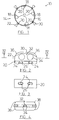
- the cage 10 comprises four cage bars 12 which are held in relative position by two substantially identical cage farmers 14.
- each cage former 14 comprises a pair of frames 16 interconnected by a plurality of (in this embodiment four) rods 18, the frames and rods suitably being welded together.
- the longitudinal axes of the cage bars 12 are substantially parallel, the longitudinal axis A-A of the cage 10 being substantially parallel with those longitudinal axes.
- the cage bars 12 are fixed to the frames 16 adjacent the connection of the frame to the respective rods 18, the fixings being effected on site by way of wire ties or the like. In this way, provided that the rods 18 are substantially equally spaced by the cage former manufacturer, the corresponding equal spacing of the bars 12 can readily be arranged.
- brackets 20 Secured to one of the frames 16 of each cage former 14, as by welding, is a set of brackets 20.
- brackets 20 there are four brackets 20, each one being located approximately mid-way between the connections of adjacent rods 18.
- each spacer 22 Secured to each bracket 20 is a spacer 22.
- each spacer is of moulded polyethylene, although other suitable materials can be used.
- the spacer has two lugs 24 which can be pressed into corresponding apertures 26 in the bracket 20.
- the shaping of the lugs 24 and apertures 26, and the resilience of the material from which the spacer is produced, provide for secure clip fitting of the spacer 22 to the bracket 20, but resist the separation thereof except under considerable force; thus, the spacer is effectively permanently secured to the bracket and so is not likely to become separated therefrom either during handling on site or during insertion of the cage into the concrete. It is expected that the spacers will be secured to the brackets by machine as part of the manufacturing process of the cage former.
- a lug 24 and the respective aperture 26 are exaggerated in Figs. 2 and 3, for clarity; in practice there would be little or no separation, i.e. the lugs 24 would be a tight mating fit within the apertures 26. Also, in practice the angle of undercut of the apertures 26, which angle is matched by the lugs, may be reduced to permit easier assembly of the spacer to the bracket, provided always that the subsequent inadvertent removal of the spacer from the bracket is substantially prevented.
- the spacer 22 has a peripheral surface 30 which as the cage is lowered into the concrete will ordinarily engage the earth surrounding the hole which has been drilled for the pile.
- the increased area of this surface compared to that of the prior art, and in particular its extended dimension in the direction parallel to the axis A, reduces the likelihood that the spacer will cut into the earth, so that the cage will be maintained centrally within the hole and no metal will encroach into the cover zone.
- the spacer 22 has a reduced thickness central portion 32 in which two openings 34 are formed.
- the central portion 32 is of reduced thickness, and the openings 34 are provided, primarily to reduce the weight and cost of the spacer whilst mantaining its integrity and minimising disruption to the concrete-mix components adjacent the spacer.
- the spacer 22 also has curved edges 36, one of which edges will in use be the leading edge as the spacer is lowered into the concrete; the curvature on this edge is to reduce the resistance provided by the spacer as it enters and moves through the concrete, and thus to reduce the likelihood that the spacer 22 will become separated from its bracket 20.
- the edges 38 are also curved, for the purpose of limiting the effective projected cross-sectional area of the spacer, so as to seek to minimise the hydraulic resistance applied during cage installation.
- brackets 20 are secured to the outer periphery of the frame 16 and the spacers 22 project outwardly therefrom; in other embodiments the brackets may be secured to the inner periphery of the frame, the spacers then perhaps having a cut-out to bridge the frame.
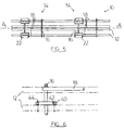
- Fig.6 shows a locator bar 40 suitable for use to locate a cage bar 12 in place of a rod 18.
- the locator bar 40 has recesses 42 adjacent its ends, and these can serve to locate wire ties 44, which in known fashion can surround a cage bar 12 are secure it to the locator bar 40.
- each cage bar 12 can be secured to a locator bar 40 at two spaced positions.
- the wire tie can be secured around the (welded) junction of the locator bar 40 with the frame 16, so that only a single securement position is provided. In such cases, the locator bar would not require recesses.
- the rods serve the three functions of ⁇ i ⁇ interconnecting the frames, ⁇ ii ⁇ carrying the spacers and ⁇ iii ⁇ providing location points for the cage bars relative to the frame.
- locator bars avoids such waste of material.
- a cage former for a cage having eight cage bars there could therefore be four rods 18 interconnecting the frames and four locator bars 40, each locator bar being located between two adjacent rods (and vice versa).
- four of the cage bars 12 would be located by rods 18 and four by the (shorter, lighter and cheaper) locator bars 40.
- the spacing function would be carried out by (at least three) separate spacers 22.
- the locator bars could be mounted upon the same frame as the spacers, or to the other frame, as desired.
- the number of rods 18 interconnecting the frames 16 can be varied according to the requirements of the particular pile cage. The most critical factor will be the size of the cage - the larger the cage typically the greater should be the number of rods 18 to provide a substantially rigid interconnection between the frames. In addition, notwithstanding the possible use of locator bars as above described, typically greater number of rods will be required for cages having a greater the number of cage bars.
- brackets and thus spacers
- the number of brackets can be varied according to the requirements of the particular pile cage and the ground conditions at the site, with once again larger cages likely utilising greater numbers of spacers.
- the number of cage formers used on a particular cage can be varied according to the requirements of the cage; longer cages (in the direction of axis A) typically requiring a greater number of cage formers.
Landscapes
- Engineering & Computer Science (AREA)
- Architecture (AREA)
- Civil Engineering (AREA)
- Structural Engineering (AREA)
- Piles And Underground Anchors (AREA)
Applications Claiming Priority (4)
| Application Number | Priority Date | Filing Date | Title |
|---|---|---|---|
| GB9809486 | 1998-05-02 | ||
| GBGB9809486.5A GB9809486D0 (en) | 1998-05-02 | 1998-05-02 | Cage former |
| GB9900766 | 1999-01-15 | ||
| GB9900766 | 1999-01-15 |
Publications (2)
| Publication Number | Publication Date |
|---|---|
| EP0955423A2 true EP0955423A2 (de) | 1999-11-10 |
| EP0955423A3 EP0955423A3 (de) | 2000-05-31 |
Family
ID=26313590
Family Applications (1)
| Application Number | Title | Priority Date | Filing Date |
|---|---|---|---|
| EP99201368A Withdrawn EP0955423A3 (de) | 1998-05-02 | 1999-05-03 | Element um einen Betonverstärkungskäfig zu bilden |
Country Status (1)
| Country | Link |
|---|---|
| EP (1) | EP0955423A3 (de) |
Cited By (6)
| Publication number | Priority date | Publication date | Assignee | Title |
|---|---|---|---|---|
| EP1156173A2 (de) | 2000-05-18 | 2001-11-21 | Rom Group Limited | Leiterförmiger Abstandhalter |
| WO2002064906A1 (en) * | 2001-02-09 | 2002-08-22 | Cagemaker Equipment Pty Ltd | A former associated with an apparatus for making cages |
| AU2002229408B2 (en) * | 2001-02-09 | 2005-06-30 | Cagemaker Equipment Pty Ltd | A former associated with an apparatus for making cages |
| WO2014198978A1 (es) * | 2013-06-13 | 2014-12-18 | Armatures Techniques Mediterranees, S.L. | Armadura asimétrica para pilotes de contención y máquina para su fabricación |
| FR3100040A1 (fr) * | 2019-08-23 | 2021-02-26 | Sefi-Intrafor | Méthode d’assemblage de cage d’armature et élément de cage d’armature pour mettre en œuvre ladite méthode |
| US11286633B2 (en) * | 2018-08-09 | 2022-03-29 | Asc Grupo Ersi, S.L.U. | System with markers for placing a retaining pile with asymmetrical reinforcement and method for using same |
Citations (2)
| Publication number | Priority date | Publication date | Assignee | Title |
|---|---|---|---|---|
| GB2235223A (en) | 1989-07-10 | 1991-02-27 | Bachy | Reinforced concrete piles |
| EP0608068A1 (de) | 1993-01-16 | 1994-07-27 | Gray Engineering Limited | Armierungskäfig für einen Betonpfahl |
Family Cites Families (3)
| Publication number | Priority date | Publication date | Assignee | Title |
|---|---|---|---|---|
| US4627211A (en) * | 1985-09-23 | 1986-12-09 | Foster Jr Thomas W | Sled for a reinforcing cage used in a pier |
| DE8702254U1 (de) * | 1987-02-13 | 1987-06-25 | BTH Biegetechnik Hasak GmbH, 8300 Altdorf | Armierungskorb für Großbohrpfähle |
| DE9011064U1 (de) * | 1990-07-26 | 1990-09-27 | BTH Biegetechnik Hasak GmbH, 8300 Altdorf | Armierungskorb für Bohrpfähle, Schlitzwände, Säulen o.dgl. |
-
1999
- 1999-05-03 EP EP99201368A patent/EP0955423A3/de not_active Withdrawn
Patent Citations (2)
| Publication number | Priority date | Publication date | Assignee | Title |
|---|---|---|---|---|
| GB2235223A (en) | 1989-07-10 | 1991-02-27 | Bachy | Reinforced concrete piles |
| EP0608068A1 (de) | 1993-01-16 | 1994-07-27 | Gray Engineering Limited | Armierungskäfig für einen Betonpfahl |
Cited By (8)
| Publication number | Priority date | Publication date | Assignee | Title |
|---|---|---|---|---|
| EP1156173A2 (de) | 2000-05-18 | 2001-11-21 | Rom Group Limited | Leiterförmiger Abstandhalter |
| WO2002064906A1 (en) * | 2001-02-09 | 2002-08-22 | Cagemaker Equipment Pty Ltd | A former associated with an apparatus for making cages |
| AU2002229408B2 (en) * | 2001-02-09 | 2005-06-30 | Cagemaker Equipment Pty Ltd | A former associated with an apparatus for making cages |
| US7124785B2 (en) | 2001-02-09 | 2006-10-24 | Cagemaker Equipment Pty. Ltd. | Former associated with an apparatus for making cages |
| WO2014198978A1 (es) * | 2013-06-13 | 2014-12-18 | Armatures Techniques Mediterranees, S.L. | Armadura asimétrica para pilotes de contención y máquina para su fabricación |
| ES2537254A1 (es) * | 2013-06-13 | 2015-06-03 | I-Tek Assembling Steel, S.E. | Armadura asimétrica para pilotes de contención y máquina para su fabricación |
| US11286633B2 (en) * | 2018-08-09 | 2022-03-29 | Asc Grupo Ersi, S.L.U. | System with markers for placing a retaining pile with asymmetrical reinforcement and method for using same |
| FR3100040A1 (fr) * | 2019-08-23 | 2021-02-26 | Sefi-Intrafor | Méthode d’assemblage de cage d’armature et élément de cage d’armature pour mettre en œuvre ladite méthode |
Also Published As
| Publication number | Publication date |
|---|---|
| EP0955423A3 (de) | 2000-05-31 |
Similar Documents
| Publication | Publication Date | Title |
|---|---|---|
| KR101901091B1 (ko) | 강판매입형 phc 파일 및 이를 적용한 흙막이 벽체 시공 방법 | |
| EP0955423A2 (de) | Element um einen Betonverstärkungskäfig zu bilden | |
| JP2001303680A (ja) | 充填鋼管部材とrc部材またはpc部材との接合部 | |
| JP6502191B2 (ja) | コンクリート構造物の補修方法 | |
| JP3628411B2 (ja) | セグメント | |
| KR101819536B1 (ko) | 철근콘크리트 벽체의 개량형 전단보강재 유닛 및 이를 이용한 철근콘크리트 벽체 배근공법 | |
| GB2235223A (en) | Reinforced concrete piles | |
| JP2000226939A (ja) | 既設構築物の耐震改修方法 | |
| JP2005120632A (ja) | トンネル用セグメント | |
| JP6886270B2 (ja) | 耐震用スリット材の設置構造および耐震用スリット材の施工方法 | |
| GB2348914A (en) | Cage former with a helical frame and integral spacers | |
| KR100291848B1 (ko) | 콘크리트 구조물에 앵커 볼트 구멍을 성형하는 방법 및 그 성형기구 | |
| JP2008025305A (ja) | トンネルの構築方法及びトンネル構造 | |
| JP2001146756A (ja) | 土留め壁・rc合成構造物 | |
| KR102321254B1 (ko) | 시트파일 설치용 케이싱 유닛 및 이를 이용한 시트파일 설치방법 | |
| GB2353552A (en) | Cage former for a concrete pile | |
| KR102743424B1 (ko) | 철근 보강체, 이를 이용한 말뚝 및 그 시공방법, 및 이러한 말뚝을 이용한 흙막이 벽체 | |
| EP1156173B1 (de) | Leiterförmiger Abstandhalter | |
| JPH062331A (ja) | 場所打鉄筋コンクリート拡底杭を構築する方法及びこれに使用する鉄筋籠 | |
| JP3020867B2 (ja) | 主筋定着プレート | |
| JP4942473B2 (ja) | 分岐トンネル施工箇所のトンネル壁の構造およびその組み立て方法 | |
| KR102762683B1 (ko) | 확장단면 철근을 구비한 국부보강 철근망 조립체, 이를 이용한 말뚝과 그 시공방법, 및 이러한 말뚝을 이용한 흙막이 벽체 | |
| JP3096660B2 (ja) | 場所打鋼管コンクリート杭の杭頭部構造及びその施工法 | |
| KR102880198B1 (ko) | 강관주 기초대 및 이를 이용한 강관주 설치방법 | |
| JP4593155B2 (ja) | トンネルの接合継手、トンネルの接合構造及びトンネルの接合方法 |
Legal Events
| Date | Code | Title | Description |
|---|---|---|---|
| PUAI | Public reference made under article 153(3) epc to a published international application that has entered the european phase |
Free format text: ORIGINAL CODE: 0009012 |
|
| AK | Designated contracting states |
Kind code of ref document: A2 Designated state(s): DE FR GB IT |
|
| AX | Request for extension of the european patent |
Free format text: AL;LT;LV;MK;RO;SI |
|
| PUAL | Search report despatched |
Free format text: ORIGINAL CODE: 0009013 |
|
| AK | Designated contracting states |
Kind code of ref document: A3 Designated state(s): AT BE CH CY DE DK ES FI FR GB GR IE IT LI LU MC NL PT SE |
|
| AX | Request for extension of the european patent |
Free format text: AL;LT;LV;MK;RO;SI |
|
| RIC1 | Information provided on ipc code assigned before grant |
Free format text: 7B 21F 27/12 A, 7E 04C 5/06 B, 7E 04C 5/20 B, 7E 04C 5/16 B |
|
| 17P | Request for examination filed |
Effective date: 20001130 |
|
| AKX | Designation fees paid |
Free format text: DE FR GB IT |
|
| STAA | Information on the status of an ep patent application or granted ep patent |
Free format text: STATUS: THE APPLICATION IS DEEMED TO BE WITHDRAWN |
|
| 18D | Application deemed to be withdrawn |
Effective date: 20011201 |