EP0955136A2 - Méthode ainsi que dispositif pour débiter en tranches des produits en forme de pains - Google Patents
Méthode ainsi que dispositif pour débiter en tranches des produits en forme de pains Download PDFInfo
- Publication number
- EP0955136A2 EP0955136A2 EP99108034A EP99108034A EP0955136A2 EP 0955136 A2 EP0955136 A2 EP 0955136A2 EP 99108034 A EP99108034 A EP 99108034A EP 99108034 A EP99108034 A EP 99108034A EP 0955136 A2 EP0955136 A2 EP 0955136A2
- Authority
- EP
- European Patent Office
- Prior art keywords
- cutting
- strand
- support
- support element
- cut
- Prior art date
- Legal status (The legal status is an assumption and is not a legal conclusion. Google has not performed a legal analysis and makes no representation as to the accuracy of the status listed.)
- Withdrawn
Links
Images

Classifications
-
- B—PERFORMING OPERATIONS; TRANSPORTING
- B26—HAND CUTTING TOOLS; CUTTING; SEVERING
- B26D—CUTTING; DETAILS COMMON TO MACHINES FOR PERFORATING, PUNCHING, CUTTING-OUT, STAMPING-OUT OR SEVERING
- B26D7/00—Details of apparatus for cutting, cutting-out, stamping-out, punching, perforating, or severing by means other than cutting
- B26D7/01—Means for holding or positioning work
-
- B—PERFORMING OPERATIONS; TRANSPORTING
- B26—HAND CUTTING TOOLS; CUTTING; SEVERING
- B26D—CUTTING; DETAILS COMMON TO MACHINES FOR PERFORATING, PUNCHING, CUTTING-OUT, STAMPING-OUT OR SEVERING
- B26D7/00—Details of apparatus for cutting, cutting-out, stamping-out, punching, perforating, or severing by means other than cutting
- B26D7/27—Means for performing other operations combined with cutting
- B26D7/32—Means for performing other operations combined with cutting for conveying or stacking cut product
- B26D2007/327—Means for performing other operations combined with cutting for conveying or stacking cut product the cut products being slices of bread
Definitions
- the invention relates to a method for cutting a strand of material into slices, in which the strand of material is advanced continuously or intermittently essentially in the horizontal direction onto a cutting device, with which slices are successively cut off from the strand of material by means of a cutting element moving in a substantially vertical plane , which are guided away from the cutting element in the form of a disc package which is extended in slices, the first disc cut from the material strand being supported by a support element of a supporting device which is guided away from the cutting element synchronously with the feed speed of the disc package. Furthermore, the invention relates to a device for performing such a cutting process.
- the aforementioned method is generally known and is frequently used when slicing a wide variety of foods, especially bread and other baked goods.
- it is necessary to support each individual cut disk after it has been separated from the strand of material in such a way that it essentially maintains its vertical orientation. Without support by a support device, the disks would fall over due to their relatively small thickness in connection with an advancing movement of the crop strand and possibly a vertical offset of the cut disks with respect to the crop strand in the cutting position, so that there would be an undesirable scale-like disc arrangement.
- this counterforce to be applied by the support element is chosen such that it is sufficiently large to support the first disk cut off from a strand of material, then this counterforce is at a point in time at which a plurality of disks have already been cut off and the disk pack that has been built up corresponds accordingly has shifted in the feed direction with the support element, unnecessarily large.
- the counterforce of the support element is set so that, together with the frictional force of a maximally long disc package, it is just large enough that the last disc to be cut off can be supported with sufficient certainty, then when the first disc is cut off there is not a sufficiently large support force, because too At this point in time, due to the missing disk pack, there is still no friction force component and therefore only the counterforce of the support element which is too low in this case is effective.
- the invention has for its object to further develop a cutting method of the type described above in such a way that damage to the last cut discs is prevented during a feed movement of the disc package and at the same time the counterforce of the support element is sufficiently large to support the first cut disc.
- this object is achieved according to the invention in that the supporting force counteracting the displacement of the supporting element decreases with increasing distance of the supporting element from the cutting member.
- the course of the decreasing supporting force can be coordinated so that the sum of the supporting force of the supporting element and the frictional force dependent on the length of the disc package remains constant and is dimensioned such that a newly cut disc can be supported with sufficient certainty.
- the feed force to be transmitted from the last cut disc for the advance of the disc package becomes so great in the course of the cutting process that product damage occurs with certain cutting goods.
- very good cutting results can be achieved even with very sensitive cutting goods.
- the supporting force at a certain distance of the supporting element from the cutting member assumes a minimum value which remains constant during the further movement.
- a particularly advantageous development of the method according to the invention provides that the supporting force is generated by friction between a moving component of the support device and a fixed component of the receiving device.
- the total counterforce available is generated from the sum of two frictional forces, which can be ensured essentially without wear and with permanently low tolerances.
- the device described above can also be used to push cutting goods sensitive to pressure loads until the last disk is cut off in the form of a disk package without damage to the product, with a sufficiently large counterforce being able to be applied by the support element in its initial dead center position even when the first disk is cut off.
- the support device advantageously has a guide device along which the support element can be guided, a frictional force occurring between a movable component of the support device and a fixed component of the receiving device or the guide device.
- the guide device is designed as a guide rod on which the support element is connected to a Guide sleeve is displaceable, wherein a frictional force occurs between the guide sleeve and a wall of the shaft of the receiving device.
- a counterforce of the support element which decreases in the feed direction can be realized particularly advantageously by the guide rod enclosing an angle with the wall of the shaft and the frictional force being brought about by a spring-loaded friction element arranged on the guide sleeve.
- the friction element is completely lifted off the wall of the shaft from a certain distance of the guide sleeve from the cutting member.
- the frictional force can be generated particularly easily if the friction element is designed as a pressure pin of a pressure piece that can be screwed into a bore in the guide sleeve.
- Such pressure pieces are cheaply available as standardized components.
- the pressure pin is made of plastic, which is why a sufficiently large frictional force results even at low contact pressures in connection with a shaft wall made of stainless steel.
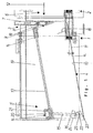
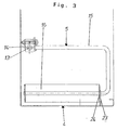
- the device 1, partially shown in FIGS. 1 to 3, for cutting a strand of material, not shown, into slices consists of a feed device 2, a cutting device 3 and a receiving device 4 for the cut slices, which has a support device 5 for preventing the cut slices from falling over.
- the device 1 shown is used to cut a loaf of bread or similar food.
- FIG. 1 of the feed device 2 which essentially consists of a feed shaft 6 and a conventional feed device (not shown) for the crop strand to be inserted into the feed shaft 6.
- the cutting device 3 has a circular knife as the cutting member 7, which rotates about an axis of rotation 8.
- the axis of rotation 8 is located in a drive arm 9, which in turn likewise performs a rotational movement about an axis of rotation, not shown in FIG Axis of rotation 8 of the circular knife runs parallel.
- the circular knife thus moves in a planetary manner around the axis of rotation of the drive arm 9.
- the circular knife is driven within the drive arm 9 with the aid of a belt drive, the drive disk of which is arranged on a knife shaft, not shown, which is guided through a hollow shaft which serves as a drive shaft for the drive arm 8.
- the speed of the circular knife is a multiple of the speed of the drive arm 9, a ratio of 10: 1 being typical.
- the drive arm 9, which carries out a uniform rotary movement about its axis of rotation, and the cutting member 7 in the form of the circular knife rotate in the opposite direction.
- the shaft floor 11 is inclined at an angle ⁇ to the horizontal or to the direction of advance (arrow 12).
- the receiving device 4 which is also designed as a removal shaft, is provided with the support device 5 which extends essentially over the entire length of the removal shaft.
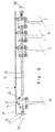
- This consists of a guide rod 13 connected to the removal shaft, a guide sleeve 14, a U-shaped bracket 15 and a plate-shaped support element 16 fastened to its lower leg.
- the guide rod 13 is connected at both ends by means of screws 17 with fastening tabs 18, which in turn are welded to a vertical wall 19 of the removal shaft.
- the guide sleeve 14 is displaceable along the guide rod 13 between the fastening tabs 18, the guide sleeve 14 being supported by rolling elements in order to minimize the frictional forces.
- the bracket 15 which is aligned vertically with its base line and horizontally with its two legs, is attached at one end to the guide sleeve 14 with a holding plate 20. Due to an elongated hole 21, the bracket can be pivoted through a certain angle.
- the bracket 15 On its lower leg, the bracket 15 carries a support plate 23, which is also provided with an elongated hole 22 and bears against the shaft floor 11.
- the end of the support element 16 is provided with two retaining tabs 24, in each of which there is a bearing bore for receiving the lower leg of the bracket 15. A possible pivot movement of the support element 16 is prevented by a stop element 25, which can only move within the elongated hole 22.
- a pressure piece 25 which is available as a commercially available component and is provided with a corresponding external thread, is screwed into a horizontal bore within the guide sleeve 14 from the side of the wall 19 of the removal shaft.
- the pressure piece 25 shown in more detail in FIGS. 4 and 5 consists of a sleeve-shaped body 26 provided with an external thread, in which a pressure bolt 28 preloaded with a spring 27 is slidably mounted in the axial direction.
- the spring 27 is supported on the side facing away from the pressure pin 28 on a stopper 29 which is provided with an external thread and can be screwed into a corresponding threaded bore in the body 26.
- the stopper 29 has one on its outward-facing end face Hexagon socket 30 on.
- a step 31 on the pressure pin 28 in conjunction with a corresponding step 32 at the end of the body prevents the pressure pin 28 from escaping.
- An outwardly stepping head 33 of the pressure bolt 28, which is made of a plastic material, is hem
- the pressure piece 25 In order to enable the pressure piece 25 to be screwed into blind bores, it is provided on its front side which is visible in FIG. 5 with a slot 34 which is interrupted by the pressure pin 28 and which allows torque to be introduced using a special screwdriver.
- the head 33 of the pressure pin 28 is in the three positions shown on the right of the guide sleeve 14 on the wall 19 of the removal shaft. Due to an angle between the center line 35 of the guide rod 13 and the wall 19 of the removal shaft that is difficult to see in the drawing, the preload with which the pressure pin 28 rests changes when the guide sleeve 14 is displaced.
- the preload of the guide sleeve 14 decreases continuously as it is moved away from the cutting device 3 via an intermediate position designated B to a position designated C. If the guide sleeve 14 moves further from the position labeled C to the left, the contact of the head 33 of the pressure pin 28 is lost, so that no frictional force between the pressure pin 28 and the wall 19 occurs. Until the stop in the form of the left retaining tab 18 is reached, a displacement of the support element 16 only affects the friction between the guide sleeve 14 and the guide rod 13 and between the support plate 23 and the shaft bottom 11. Due to the inclination of the guide rod 13 by the angle ⁇ with respect to the horizontal, a proportion of the weight acts to support the displacement of the guide sleeve 14.
- the guide rod 13 can be displaced parallel to the arrows 36 at both ends due to elongated holes in both retaining tabs 18, so that the initial preloading of the pressure pin 28 and the removal of the position C from which the pressure pin 28 occurs the system of its stage 31 loses contact with the wall 19, is individually adjustable.
- the cutting method according to the invention is carried out with the device 1 described above as follows:
- the support element 16 is located together with the bracket 15 and the guide sleeve 14 in the position denoted by A in FIG. 2, which is also indicated in FIG. 1.
- the first cut disc is securely supported due to the large frictional force between the pressure pin 28 and the wall 19 of the removal shaft, which counteracts a displacement of the support element 16.
- the feed force is transmitted to the support element 16 via the already cut slice or slices, which, contrary to the frictional force on the pressure bolt 28, also results in a displacement of the guide sleeve 14 and thus of the support element 16.
- the frictional force between the pressure pin 28 and the wall 19 of the removal shaft decreases continuously with increasing distance of the support element 16 from the cutting device 3, the frictional force which is required for displacing the cut-off slices along the surface 10 of the shaft bottom 11 increases continuously.
Landscapes
- Life Sciences & Earth Sciences (AREA)
- Forests & Forestry (AREA)
- Engineering & Computer Science (AREA)
- Mechanical Engineering (AREA)
- Crushing And Pulverization Processes (AREA)
- Perforating, Stamping-Out Or Severing By Means Other Than Cutting (AREA)
Applications Claiming Priority (2)
| Application Number | Priority Date | Filing Date | Title |
|---|---|---|---|
| DE19820492 | 1998-05-07 | ||
| DE1998120492 DE19820492C1 (de) | 1998-05-07 | 1998-05-07 | Verfahren und Vorrichtung zum Schneiden eines Gutsstrangs in Scheiben |
Publications (2)
| Publication Number | Publication Date |
|---|---|
| EP0955136A2 true EP0955136A2 (fr) | 1999-11-10 |
| EP0955136A3 EP0955136A3 (fr) | 2002-01-23 |
Family
ID=7867012
Family Applications (1)
| Application Number | Title | Priority Date | Filing Date |
|---|---|---|---|
| EP99108034A Withdrawn EP0955136A3 (fr) | 1998-05-07 | 1999-04-23 | Méthode ainsi que dispositif pour débiter en tranches des produits en forme de pains |
Country Status (2)
| Country | Link |
|---|---|
| EP (1) | EP0955136A3 (fr) |
| DE (1) | DE19820492C1 (fr) |
Families Citing this family (4)
| Publication number | Priority date | Publication date | Assignee | Title |
|---|---|---|---|---|
| DE102012216358B3 (de) * | 2012-09-14 | 2013-09-19 | Uwe Reifenhäuser | Verfahren und Vorrichtung zum Schneiden von Brot in Scheiben |
| DE102013203990A1 (de) | 2013-03-08 | 2014-09-11 | Uwe Reifenhäuser | Verfahren sowie Vorrichtung zum Schneiden von Brot in Scheiben |
| DE102012216379A1 (de) | 2012-09-14 | 2014-03-20 | Uwe Reifenhäuser | Vorrichtung zum Schneiden von Brot in Scheiben |
| EP2708337B1 (fr) | 2012-09-14 | 2015-01-28 | Uwe Reifenhäuser | Procédé destiné à couper du pain et dispositif correspondant |
Family Cites Families (3)
| Publication number | Priority date | Publication date | Assignee | Title |
|---|---|---|---|---|
| GB464310A (en) * | 1936-04-22 | 1937-04-15 | Us Slicing Machine Co | Improvements relating to slicing-machine slice-receiving trays |
| US2242935A (en) * | 1938-07-28 | 1941-05-20 | Us Slicing Machine Co | Slicing machine |
| DE1219639B (de) * | 1964-01-17 | 1966-06-23 | Hermann Scharfen Maschinenfabr | Scheibenschneidemaschine, insbesondere Brotschneidemaschine fuer Gewerbebetriebe |
-
1998
- 1998-05-07 DE DE1998120492 patent/DE19820492C1/de not_active Expired - Fee Related
-
1999
- 1999-04-23 EP EP99108034A patent/EP0955136A3/fr not_active Withdrawn
Also Published As
| Publication number | Publication date |
|---|---|
| DE19820492C1 (de) | 1999-08-12 |
| EP0955136A3 (fr) | 2002-01-23 |
Similar Documents
| Publication | Publication Date | Title |
|---|---|---|
| EP0077932B1 (fr) | Dispositif pour assembler des tôles par une jonction similaire à une rivure | |
| DE2154000A1 (de) | Verfahren und Vorrichtung zur Herstellung eines Gerichts | |
| EP0093318A2 (fr) | Machine à découenner | |
| DE2718028C2 (de) | Semmelschneidmaschine | |
| DE2208642A1 (de) | Verfahren und maschine zum zerschneiden von fleischscheiben | |
| DE19820492C1 (de) | Verfahren und Vorrichtung zum Schneiden eines Gutsstrangs in Scheiben | |
| EP1285581A2 (fr) | Procédé et système pour former des produits pâteux roulés, notamment des croissants, à partir d'une pièce de pâte plane découpée | |
| EP1704971B1 (fr) | Méthode et dispositif de coupe pour produits alimentaires ayant une forme allongée | |
| DE3926588C1 (fr) | ||
| EP0166340A2 (fr) | Dispositif de préhension d'une pièce flexible plane à partir d'un support | |
| DE3020671C2 (fr) | ||
| DE69311027T2 (de) | Rotierendes Schneidwerkzeug, insbesondere zum Schneiden von Tabak | |
| EP1704973B2 (fr) | Méthode et appareil pour couper des produits alimentaires allongés | |
| DD141485A5 (de) | Verfahren zum kontinuierlichen schneiden einer tafel | |
| DE3615381C2 (de) | Fuehrungsvorrichtung fuer den messerbalken einer schere zur blechbearbeitung | |
| DE3909639C2 (fr) | ||
| DE102014117848B3 (de) | Längsschneiden eines Bandes einer weichen Lebensmittelmasse | |
| DE2109216A1 (de) | Vorrichtung zum Anbringen von Formlöchern in einem Blechband | |
| EP1145654B1 (fr) | Eplucheuse | |
| DE2205714B1 (de) | Vorrichtung zum abschneiden einzelner, jeweils einer lasche entsprechender abschnitte von einem in gestalt eines fortlaufenden bandes zugefuehrten laschenmaterial fuer die endlos-formularsatzherstellung | |
| DE1296501B (de) | Vorrichtung zum Aufbringen von Klebestreifenabschnitten auf ein be-wegliches Werkstueck | |
| DE2822771C2 (de) | Vorrichtung zum Herstellen von an den Stirnseiten angefasten Dübeln aus runden Holzstäben | |
| DE69014720T2 (de) | Aufschnittmaschine. | |
| DE3617480A1 (de) | Speckentschwartungsmaschine | |
| DE20120234U1 (de) | Maschine zum Schneiden von Brot und vergleichbarer Nahrungsmittel |
Legal Events
| Date | Code | Title | Description |
|---|---|---|---|
| PUAI | Public reference made under article 153(3) epc to a published international application that has entered the european phase |
Free format text: ORIGINAL CODE: 0009012 |
|
| AK | Designated contracting states |
Kind code of ref document: A2 Designated state(s): AT BE CH CY DE DK ES FI FR GB GR IE IT LI LU MC NL PT SE Kind code of ref document: A2 Designated state(s): GB |
|
| AX | Request for extension of the european patent |
Free format text: AL;LT;LV;MK;RO;SI |
|
| PUAL | Search report despatched |
Free format text: ORIGINAL CODE: 0009013 |
|
| AK | Designated contracting states |
Kind code of ref document: A3 Designated state(s): AT BE CH CY DE DK ES FI FR GB GR IE IT LI LU MC NL PT SE |
|
| AX | Request for extension of the european patent |
Free format text: AL;LT;LV;MK;RO;SI |
|
| AKX | Designation fees paid |
Free format text: GB |
|
| REG | Reference to a national code |
Ref country code: DE Ref legal event code: 8566 |
|
| 18D | Application deemed to be withdrawn |
Effective date: 20020724 |
|
| REG | Reference to a national code |
Ref country code: HK Ref legal event code: WD Ref document number: 1024442 Country of ref document: HK |