EP0954064A2 - Steckverbindungspaar und Steckverbindersatz - Google Patents
Steckverbindungspaar und Steckverbindersatz Download PDFInfo
- Publication number
- EP0954064A2 EP0954064A2 EP99107451A EP99107451A EP0954064A2 EP 0954064 A2 EP0954064 A2 EP 0954064A2 EP 99107451 A EP99107451 A EP 99107451A EP 99107451 A EP99107451 A EP 99107451A EP 0954064 A2 EP0954064 A2 EP 0954064A2
- Authority
- EP
- European Patent Office
- Prior art keywords
- male
- connectors
- connector
- female connector
- female
- Prior art date
- Legal status (The legal status is an assumption and is not a legal conclusion. Google has not performed a legal analysis and makes no representation as to the accuracy of the status listed.)
- Granted
Links
Images


Classifications
-
- H—ELECTRICITY
- H01—ELECTRIC ELEMENTS
- H01R—ELECTRICALLY-CONDUCTIVE CONNECTIONS; STRUCTURAL ASSOCIATIONS OF A PLURALITY OF MUTUALLY-INSULATED ELECTRICAL CONNECTING ELEMENTS; COUPLING DEVICES; CURRENT COLLECTORS
- H01R43/00—Apparatus or processes specially adapted for manufacturing, assembling, maintaining, or repairing of line connectors or current collectors or for joining electric conductors
- H01R43/18—Apparatus or processes specially adapted for manufacturing, assembling, maintaining, or repairing of line connectors or current collectors or for joining electric conductors for manufacturing bases or cases for contact members
-
- B—PERFORMING OPERATIONS; TRANSPORTING
- B29—WORKING OF PLASTICS; WORKING OF SUBSTANCES IN A PLASTIC STATE IN GENERAL
- B29C—SHAPING OR JOINING OF PLASTICS; SHAPING OF MATERIAL IN A PLASTIC STATE, NOT OTHERWISE PROVIDED FOR; AFTER-TREATMENT OF THE SHAPED PRODUCTS, e.g. REPAIRING
- B29C45/00—Injection moulding, i.e. forcing the required volume of moulding material through a nozzle into a closed mould; Apparatus therefor
- B29C45/17—Component parts, details or accessories; Auxiliary operations
- B29C45/26—Moulds
- B29C45/2673—Moulds with exchangeable mould parts, e.g. cassette moulds
-
- H—ELECTRICITY
- H01—ELECTRIC ELEMENTS
- H01R—ELECTRICALLY-CONDUCTIVE CONNECTIONS; STRUCTURAL ASSOCIATIONS OF A PLURALITY OF MUTUALLY-INSULATED ELECTRICAL CONNECTING ELEMENTS; COUPLING DEVICES; CURRENT COLLECTORS
- H01R13/00—Details of coupling devices of the kinds covered by groups H01R12/70 or H01R24/00 - H01R33/00
- H01R13/64—Means for preventing incorrect coupling
- H01R13/645—Means for preventing incorrect coupling by exchangeable elements on case or base
- H01R13/6456—Means for preventing incorrect coupling by exchangeable elements on case or base comprising keying elements at different positions along the periphery of the connector
Definitions
- the present invention relates to a male and female connector pair and to a set of mating connectors comprising a plurality of such male and female connector pairs.
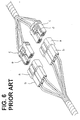
- FIG. 6 shows conventional male and female connector pairs.
- This identification means is constructed as follows. A rib d extending in a direction of connection is formed in a right end position of the upper surface of the female housing c located at a right side in FIG. 6 and a receiving groove (not shown) along which the rib d is fittable is formed in a corresponding position of the inner surface of the receptacle a of the male housing b with which the above female housing c is to be connected.
- a rib e is formed in a left end position of the upper surface of the female housing c located at a left side in FIG. 6 and a receiving groove (not shown) along which the rib e is fittable is formed in a corresponding position of the inner surface of the receptacle a of the male housing b with which the above female housing c is to be connected.
- the ribs d, e are formed on the female housings c and the receiving grooves are formed in the male housings b in order to prevent an error assembling.
- the ribs d, e of the female housings c can be easily identified by seeing or touching the connector housings.
- the confirmation of the receiving grooves of the male housings is accompanied by a cumbersome operation of looking into the receptacles a or inserting a finger thereinto.
- an object of the present invention is to improve a function of preventing an error assembling of male and female connectors.
- a male and female connector pair substantially connectable with each other, where identification means for showing that male and female connectors are a proper mating pair are provided on outer surfaces of the both connectors.
- the identification means are provided on the outer surfaces of both connectors, whether or not the combination of the connectors is proper can be securely discriminated by seeing or touching. Therefore, the connectors have an excellent function of preventing an error assembling.
- the identification means are in the form of a projection and/or a recess so as to be recognizable by touching.
- the identification means comprise:
- a discrimination by touching as to whether or not the combination of the connectors is proper is made by judging whether or not the error assembling preventing portion of the one connector and the identification portion of the other connector correspond, preferably are substantially aligned on the same straight line with the two connectors faced preferably exactly opposite to each other. Since the identification means correspond, preferably are substantially aligned on the same straight line, if the combination of the two connectors is proper, the connectors can be easily and securely identified.
- the identification means is in the form to be only visually identifiable.
- the identification means is in the form of one or more colours.
- a set of mating connectors comprising two or more male and female connector pairs according to the invention and being connectable with each other, wherein the identification means provided on each male and female connector pair are different.
- the error assembling preventing portion and/or the identification portion of each male and female connector pair are positioned in different positions, preferably in positions being laterally displaced or shifted or displaced in a direction at an angle different from 0° or 180° with respect to the connection direction with respect to each other.
- FIGS. 1 to 5 a first embodiment of the invention is described with reference to FIGS. 1 to 5.
- FIG. 1 shows an end of a wiring harness 3 obtained by bundling a first wire group 1 and a second wire group 2 which are each comprised of a plurality of wires W and an end of a wiring harness 6 obtained by bundling a first wire group 4 and a second wire group 5 which are each also comprised of a plurality of wires W.
- First and second male connectors 7a, 7b are connected with an end of the wire group 1 and an end of the wire group 2, respectively.
- a first female connector 8a paired with the first male connector 7a is connected or connectable with an end of the first wire group 4 of the wiring harness 6, and a second female connector 8b paired with the second male connector 7b is connected or connectable with an end of the second wire group 5.
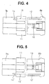
- FIGS. 2 and 4 show the mating first male and female connectors 7a and 8a.
- the first male connector 7a is formed with cavities 10 into which male terminal fittings (not shown) connected with the wires W are at least partially insertable, and a receptacle 11 into which a mating or front end portion of the first female connector 8a is at least partially fittable or insertable is formed at the mating or front end of the first male connector 7a.
- the first female connector 8a is formed with cavities 10 into which female terminal fittings (not shown) connected with the wires W are at least partially insertable, and a mating or front end thereof is so shaped as to be substantially closely fittable into the receptacle 11 of the first male connector 7a.
- an error assembling preventing rib 12 as an error assembling preventing portion in a first lateral position, e.g. in a position toward the right end when viewed from behind with respect to a direction C of connection with the first male connector 7a.
- the first male connector 7a is formed with an identification rib 14, as an identification portion, in a position substantially corresponding to that of the error assembling preventing rib 12.
- the rib 14 extending substantially backward (along the direction C of connection away from the mating end portion) from the base end of the receptacle 11 is substantially located on the same straight line as the rib 12 or substantially in flush therewith when the first male connector 7a and the first female connector 8a are preferably properly faced to each other.
- a receiving groove 15, as a receiving portion, along which the error assembling preventing rib 12 of the first female connector 8a is at least partially fittable or insertable and which substantially extends in the direction C of connection is formed in a position corresponding to the rib 12. Accordingly, the first male and female connectors 7a and 8a are connectable only when being preferably properly faced to each other as shown in FIGS. 1, 2 and 4.
- a locking portion 16 is formed in the middle of the upper surface of the first female connector 8a.
- the locking portion 16 is substantially engageable with an engaging portion (not shown) formed in the inner surface of the receptacle 11 when the first male and female connectors 7a and 8a are completely connected with each other, thereby locking the connectors 7a and 8a into each other.
- FIGS. 3 and 5 show the mating second male and female connectors 7b and 8b.
- the second male and female connectors 7b and 8b have substantially the same constructions as the first male and female connectors 7a and 8a, respectively. Differences lie in the position of the error assembling preventing rib 12' as the error assembling preventing portion, that of the identification rib 14' as the identification portion and that of the receiving groove 15' as the receiving portion.
- the rib 12' is formed at a second position being preferably spaced in a lateral direction from the first position, e.g. at the left side of the second female connector 8b.
- the second male connector 7b is formed with the identification rib 14' substantially corresponding to the error assembling preventing rib 12'.
- the rib 14' extending substantially backward from the base end of the receptacle 11 is located substantially on the same straight line as or substantially in flush with the rib 12' when the second male connector 7b and the first female connector 8b are properly faced to each other.
- the receiving groove 15' along which the error assembling preventing rib 12' of the second female connector 8b is at least partially fittable and which extends substantially in the direction of connection C is formed in a position substantially corresponding to the rib 12'. Accordingly, the second male and female connectors 7b and 8b are connectable only when being properly faced to each other as shown in FIGS. 1, 3 and 5.
- the male and female connectors according to this embodiment are constructed as above.
- the discrimination as to whether or not the combination of the connectors is proper can be made by judging whether or not the ribs 12 and 14 or 12' and 14' substantially correspond or are substantially aligned on the same straight line. This judgment can be easily made by seeing and/or touching. Therefore, the connecting operation can be easily and quickly performed even under the condition that the connector housings are connected by feeling without seeing them.
Landscapes
- Engineering & Computer Science (AREA)
- Manufacturing & Machinery (AREA)
- Mechanical Engineering (AREA)
- Details Of Connecting Devices For Male And Female Coupling (AREA)
- Connector Housings Or Holding Contact Members (AREA)
Applications Claiming Priority (4)
| Application Number | Priority Date | Filing Date | Title |
|---|---|---|---|
| JP11851398A JP3248484B2 (ja) | 1998-04-28 | 1998-04-28 | コネクタ成型金型 |
| JP11851398 | 1998-04-28 | ||
| JP15929098A JPH11354213A (ja) | 1998-06-08 | 1998-06-08 | 雌雄コネクタ |
| JP15929098 | 1998-06-08 |
Publications (3)
| Publication Number | Publication Date |
|---|---|
| EP0954064A2 true EP0954064A2 (de) | 1999-11-03 |
| EP0954064A3 EP0954064A3 (de) | 2000-02-23 |
| EP0954064B1 EP0954064B1 (de) | 2004-06-30 |
Family
ID=26456438
Family Applications (1)
| Application Number | Title | Priority Date | Filing Date |
|---|---|---|---|
| EP99107451A Expired - Lifetime EP0954064B1 (de) | 1998-04-28 | 1999-04-28 | Steckverbindungspaar und Steckverbindersatz |
Country Status (4)
| Country | Link |
|---|---|
| US (1) | US6296523B1 (de) |
| EP (1) | EP0954064B1 (de) |
| CN (1) | CN1100369C (de) |
| DE (1) | DE69918365T2 (de) |
Cited By (3)
| Publication number | Priority date | Publication date | Assignee | Title |
|---|---|---|---|---|
| FR2941098A1 (fr) * | 2009-01-09 | 2010-07-16 | Peugeot Citroen Automobiles Sa | Dispositif de connexion comportant au moins deux conducteurs pour realiser une liaison electrique entre deux organes electriques |
| EP2355257A1 (de) * | 2010-01-27 | 2011-08-10 | Lennox Industries Inc. | Verdrahtungsanschlussgehäuse |
| US10012403B2 (en) | 2009-05-21 | 2018-07-03 | Lennox Industries Inc. | Wiring connector housing |
Families Citing this family (17)
| Publication number | Priority date | Publication date | Assignee | Title |
|---|---|---|---|---|
| US6702617B1 (en) * | 2002-08-22 | 2004-03-09 | International Business Machines Corporation | Electrical connector with geometrical continuity for transmitting very high frequency data signals |
| JP3804657B2 (ja) * | 2003-01-08 | 2006-08-02 | ソニー株式会社 | 外部記憶装置 |
| FR2928772B1 (fr) * | 2008-03-14 | 2014-06-13 | Centre Nat Etd Spatiales | Dispositif pour prevenir l'etablissement d'un arc electrique entre deux elements conducteurs. |
| DE102009052772B4 (de) * | 2008-12-01 | 2014-02-13 | Sumitomo Wiring Systems, Ltd. | Ein Verbinder |
| CN102468578B (zh) * | 2010-11-16 | 2016-03-16 | 泰科电子(上海)有限公司 | 电连接器的壳体的防误插接装置的设计方法 |
| AU2012228977A1 (en) | 2011-03-17 | 2013-09-19 | Patrick Campbell | On-shelf tracking (OST) system |
| US10378956B2 (en) | 2011-03-17 | 2019-08-13 | Triangle Strategy Group, LLC | System and method for reducing false positives caused by ambient lighting on infra-red sensors, and false positives caused by background vibrations on weight sensors |
| US10083453B2 (en) | 2011-03-17 | 2018-09-25 | Triangle Strategy Group, LLC | Methods, systems, and computer readable media for tracking consumer interactions with products using modular sensor units |
| KR101953903B1 (ko) * | 2012-07-05 | 2019-03-04 | 현대모비스 주식회사 | 차량용 센서 장착 구조체 |
| US9142907B2 (en) * | 2013-12-10 | 2015-09-22 | Delphi Technologies, Inc. | Electrical connection system |
| WO2015103278A1 (en) * | 2014-01-02 | 2015-07-09 | Triangle Strategy Group, LLC | Methods, systems, and computer readable media for tracking human interactions with objects using modular sensor segments |
| US9577362B1 (en) * | 2015-11-10 | 2017-02-21 | Amphenol Corporation | Electrical connector assembly |
| USD883932S1 (en) * | 2018-10-03 | 2020-05-12 | Xiamen Ghgm Industrial Trade Co., Ltd. | Electrical connector plastic shell assembly |
| USD876361S1 (en) * | 2019-09-26 | 2020-02-25 | Qingdao Baobin Electronics Technology Co., Ltd. | Wire connector |
| USD875047S1 (en) * | 2019-09-26 | 2020-02-11 | Qingdao Baobin Electronics Technology Co., Ltd. | Wire connector |
| DE102020000422A1 (de) * | 2020-01-24 | 2021-07-29 | Drägerwerk AG & Co. KGaA | Elektrische Steckverbindung für eine Medizingeräteanordnung |
| JP7428973B2 (ja) * | 2020-09-28 | 2024-02-07 | 住友電装株式会社 | コネクタ |
Family Cites Families (17)
| Publication number | Priority date | Publication date | Assignee | Title |
|---|---|---|---|---|
| US5894661A (en) | 1995-03-15 | 1999-04-20 | Sumitomo Wiring Systems, Ltd. | Connector manufacturing method |
| JPS60152272A (ja) | 1984-01-19 | 1985-08-10 | Toshiba Corp | 電源装置 |
| JPS61211010A (ja) | 1985-03-15 | 1986-09-19 | Tamura Electric Works Ltd | ボタン電話主装置の筐体の製造方法 |
| DE3601115A1 (de) * | 1986-01-16 | 1987-07-23 | Fraunhofer Ges Forschung | Unverwechselbare steckverbindung |
| US4861534A (en) | 1988-06-29 | 1989-08-29 | International Business Machines Corporation | Method and apparatus for the injection molding of circuit boards |
| IE892171A1 (en) | 1989-07-06 | 1991-01-16 | Desbury Ltd | A mould for a cable connector |
| JPH0349174A (ja) | 1989-07-17 | 1991-03-01 | Nippondenso Co Ltd | コネクタ |
| JPH04237978A (ja) * | 1991-01-18 | 1992-08-26 | Amp Japan Ltd | タップコネクタ |
| JP2995934B2 (ja) * | 1991-08-01 | 1999-12-27 | 住友電装株式会社 | 接続コネクタ |
| JPH0635400A (ja) * | 1992-07-15 | 1994-02-10 | Nippondenso Co Ltd | 車載用画像表示装置 |
| JP2991327B2 (ja) | 1994-12-02 | 1999-12-20 | 矢崎総業株式会社 | 防水コネクタハウジングの製造方法 |
| US5814356A (en) | 1995-03-10 | 1998-09-29 | Sumitomo Wiring Systems, Ltd. | Manufacturing metal mold for assembling a resin molded assembly |
| US5915760A (en) | 1995-03-16 | 1999-06-29 | Sumitomo Wiring Systems, Ltd. | Method of producing resin-molded product |
| US5660782A (en) | 1995-05-31 | 1997-08-26 | The Whitaker Corporation | Method and apparatus for injection molding of selected parts |
| JP3266782B2 (ja) | 1995-06-05 | 2002-03-18 | 矢崎総業株式会社 | リヤホルダー付きコネクタの製造方法 |
| KR0156970B1 (ko) | 1995-08-01 | 1998-12-15 | 유기범 | 광 케이블 접속용 다심 콘넥터를 제작하기 위한 금형 장치 |
| JP3454457B2 (ja) | 1997-01-09 | 2003-10-06 | 矢崎総業株式会社 | 成形物の製造方法及び成形用金型 |
-
1999
- 1999-04-28 US US09/300,504 patent/US6296523B1/en not_active Expired - Lifetime
- 1999-04-28 DE DE69918365T patent/DE69918365T2/de not_active Expired - Lifetime
- 1999-04-28 EP EP99107451A patent/EP0954064B1/de not_active Expired - Lifetime
- 1999-04-28 CN CN99106038A patent/CN1100369C/zh not_active Expired - Lifetime
Cited By (4)
| Publication number | Priority date | Publication date | Assignee | Title |
|---|---|---|---|---|
| FR2941098A1 (fr) * | 2009-01-09 | 2010-07-16 | Peugeot Citroen Automobiles Sa | Dispositif de connexion comportant au moins deux conducteurs pour realiser une liaison electrique entre deux organes electriques |
| US10012403B2 (en) | 2009-05-21 | 2018-07-03 | Lennox Industries Inc. | Wiring connector housing |
| EP2355257A1 (de) * | 2010-01-27 | 2011-08-10 | Lennox Industries Inc. | Verdrahtungsanschlussgehäuse |
| AU2010227043B2 (en) * | 2010-01-27 | 2016-05-26 | Lennox Industries Inc. | Wiring connector housing |
Also Published As
| Publication number | Publication date |
|---|---|
| EP0954064B1 (de) | 2004-06-30 |
| US6296523B1 (en) | 2001-10-02 |
| EP0954064A3 (de) | 2000-02-23 |
| DE69918365D1 (de) | 2004-08-05 |
| CN1100369C (zh) | 2003-01-29 |
| DE69918365T2 (de) | 2005-07-14 |
| CN1233864A (zh) | 1999-11-03 |
Similar Documents
| Publication | Publication Date | Title |
|---|---|---|
| EP0954064B1 (de) | Steckverbindungspaar und Steckverbindersatz | |
| US6638109B2 (en) | Connector with a side retainer | |
| EP2122771B1 (de) | Steckbares schraubenloses drahtverbindersystem | |
| US6116939A (en) | Connector lock mechanism | |
| EP0676828B1 (de) | Steckverbinder | |
| EP1587178B1 (de) | Verbinder | |
| US7108534B2 (en) | Electrical connector assembly having at least two keying arrangements | |
| US10340621B2 (en) | Connector with moving plate having partition between terminals to prevent short-circuit | |
| US7404744B2 (en) | Connector and a connector assembly | |
| US6769934B2 (en) | Connector and an unlocking jig therefor | |
| US6497591B2 (en) | Connector | |
| US5746620A (en) | Electrical connector including means for terminating wires | |
| EP1592091B1 (de) | Zwischenverbinder | |
| US6599154B2 (en) | Connector with obliquely Moveable retainer | |
| EP0963009A1 (de) | Eine Vorrichtung zur Verhinderung einer fehlerhaften Zusammensetzung eines Verbindergehäuses mit einem Deckel und einen Verbinder mit einer solchen Vorrichtung | |
| EP1548894B1 (de) | Verbinder | |
| US9972921B2 (en) | Connector with sub-housing and uniting portion | |
| EP1557908A2 (de) | Ein verbinder | |
| EP0996200A2 (de) | Mehrpoliger wasserdichter Steckverbinder | |
| US6358098B1 (en) | Terminal and a joint connector | |
| US5346412A (en) | Break away key and latch assembly | |
| US6692303B2 (en) | Terminal fitting, a connector and a method for forming a terminal fitting that facilitate insertion of the terminal fitting into the connector | |
| EP1801925B1 (de) | Verbinder und Verbinderanordnung | |
| EP0660446A1 (de) | Elektrischer Verbinder mit flexiblen Kontaktsperrmitteln und Lagesicherungsvorrichtung für die Kontakte | |
| CN100559665C (zh) | 带锁定机构的电连接器 |
Legal Events
| Date | Code | Title | Description |
|---|---|---|---|
| PUAI | Public reference made under article 153(3) epc to a published international application that has entered the european phase |
Free format text: ORIGINAL CODE: 0009012 |
|
| 17P | Request for examination filed |
Effective date: 19990520 |
|
| AK | Designated contracting states |
Kind code of ref document: A2 Designated state(s): DE FR GB IT |
|
| AX | Request for extension of the european patent |
Free format text: AL;LT;LV;MK;RO;SI |
|
| PUAL | Search report despatched |
Free format text: ORIGINAL CODE: 0009013 |
|
| AK | Designated contracting states |
Kind code of ref document: A3 Designated state(s): AT BE CH CY DE DK ES FI FR GB GR IE IT LI LU MC NL PT SE |
|
| AX | Request for extension of the european patent |
Free format text: AL;LT;LV;MK;RO;SI |
|
| RIC1 | Information provided on ipc code assigned before grant |
Free format text: 7H 01R 13/64 A, 7H 01R 13/645 B, 7H 01R 43/18 B |
|
| 17Q | First examination report despatched |
Effective date: 20000718 |
|
| AKX | Designation fees paid |
Free format text: DE FR GB IT |
|
| GRAP | Despatch of communication of intention to grant a patent |
Free format text: ORIGINAL CODE: EPIDOSNIGR1 |
|
| GRAS | Grant fee paid |
Free format text: ORIGINAL CODE: EPIDOSNIGR3 |
|
| GRAA | (expected) grant |
Free format text: ORIGINAL CODE: 0009210 |
|
| AK | Designated contracting states |
Kind code of ref document: B1 Designated state(s): DE FR GB IT |
|
| PG25 | Lapsed in a contracting state [announced via postgrant information from national office to epo] |
Ref country code: IT Free format text: LAPSE BECAUSE OF FAILURE TO SUBMIT A TRANSLATION OF THE DESCRIPTION OR TO PAY THE FEE WITHIN THE PRESCRIBED TIME-LIMIT;WARNING: LAPSES OF ITALIAN PATENTS WITH EFFECTIVE DATE BEFORE 2007 MAY HAVE OCCURRED AT ANY TIME BEFORE 2007. THE CORRECT EFFECTIVE DATE MAY BE DIFFERENT FROM THE ONE RECORDED. Effective date: 20040630 |
|
| REG | Reference to a national code |
Ref country code: GB Ref legal event code: FG4D |
|
| REF | Corresponds to: |
Ref document number: 69918365 Country of ref document: DE Date of ref document: 20040805 Kind code of ref document: P |
|
| ET | Fr: translation filed | ||
| PG25 | Lapsed in a contracting state [announced via postgrant information from national office to epo] |
Ref country code: GB Free format text: LAPSE BECAUSE OF NON-PAYMENT OF DUE FEES Effective date: 20050428 |
|
| PLBE | No opposition filed within time limit |
Free format text: ORIGINAL CODE: 0009261 |
|
| STAA | Information on the status of an ep patent application or granted ep patent |
Free format text: STATUS: NO OPPOSITION FILED WITHIN TIME LIMIT |
|
| 26N | No opposition filed |
Effective date: 20050331 |
|
| GBPC | Gb: european patent ceased through non-payment of renewal fee |
Effective date: 20050428 |
|
| PG25 | Lapsed in a contracting state [announced via postgrant information from national office to epo] |
Ref country code: FR Free format text: LAPSE BECAUSE OF NON-PAYMENT OF DUE FEES Effective date: 20051230 |
|
| REG | Reference to a national code |
Ref country code: FR Ref legal event code: ST Effective date: 20051230 |
|
| REG | Reference to a national code |
Ref country code: DE Ref legal event code: R084 Ref document number: 69918365 Country of ref document: DE |
|
| PGFP | Annual fee paid to national office [announced via postgrant information from national office to epo] |
Ref country code: DE Payment date: 20180417 Year of fee payment: 20 |
|
| REG | Reference to a national code |
Ref country code: DE Ref legal event code: R071 Ref document number: 69918365 Country of ref document: DE |