EP0953832B1 - Kapazitiver Druckwandler mit reduziertem Ausgangsfehler - Google Patents
Kapazitiver Druckwandler mit reduziertem Ausgangsfehler Download PDFInfo
- Publication number
- EP0953832B1 EP0953832B1 EP99302927A EP99302927A EP0953832B1 EP 0953832 B1 EP0953832 B1 EP 0953832B1 EP 99302927 A EP99302927 A EP 99302927A EP 99302927 A EP99302927 A EP 99302927A EP 0953832 B1 EP0953832 B1 EP 0953832B1
- Authority
- EP
- European Patent Office
- Prior art keywords
- detect
- source
- plate
- guard
- substrate
- Prior art date
- Legal status (The legal status is an assumption and is not a legal conclusion. Google has not performed a legal analysis and makes no representation as to the accuracy of the status listed.)
- Expired - Lifetime
Links
Images


Classifications
-
- G—PHYSICS
- G01—MEASURING; TESTING
- G01L—MEASURING FORCE, STRESS, TORQUE, WORK, MECHANICAL POWER, MECHANICAL EFFICIENCY, OR FLUID PRESSURE
- G01L9/00—Measuring steady of quasi-steady pressure of fluid or fluent solid material by electric or magnetic pressure-sensitive elements; Transmitting or indicating the displacement of mechanical pressure-sensitive elements, used to measure the steady or quasi-steady pressure of a fluid or fluent solid material, by electric or magnetic means
- G01L9/0041—Transmitting or indicating the displacement of flexible diaphragms
- G01L9/0072—Transmitting or indicating the displacement of flexible diaphragms using variations in capacitance
- G01L9/0075—Transmitting or indicating the displacement of flexible diaphragms using variations in capacitance using a ceramic diaphragm, e.g. alumina, fused quartz, glass
Definitions
- This invention relates generally to fluid pressure sensors and more particularly to capacitive pressure transducers having reduced output error.
- a known pressure sensor as shown in U.S. Patent No. 4,716,492, comprises a capacitive pressure transducer having a thin, relatively flexible ceramic diaphragm mounted in closely spaced, sealed, overlying relation to a rigid ceramic substrate and having metal coatings deposited on respective opposing surfaces of the diaphragm and substrate to serve as source and detect capacitor plates arranged in predetermined closely spaced relation to each other to form a capacitor. Electrically conductive traces extend out to pins received in bores formed through the substrate located between the capacitor plates and the outer periphery of the diaphragm and substrate which are connected to an electronic conditioning module attached to the transducer.
- the diaphragm flexes in response to pressure and causes the source and detect plates to move closer together thereby increasing the capacitance between the plates which is measured by the electronic conditioning module.
- An annular guard ring of electrically conductive material is printed on the substrate around the detect plate and electrically held at the same voltage as the detect plate.
- the guard ring has an inner diameter slightly less than the diameter of the circular source plate. This ring serves as a guard to reduce the electrical field intensity between the source and detect plates at the edges of the detect plate. These fringe electric fields are undesirable because they cause a non-linear pressure transducer output.
- the electronic conditioning module is designed to measure the capacitance between the source and detect plates only and is insensitive to capacitance between the source plate and the guard, between the detect plate and the guard or between either the source plate or the detect plate and the housing of the sensor.
- the transducer output shifts by up to 1% full scale or more. Since capacitance is dependent upon both the electric field between the capacitor plates and any dielectric material within the electric field, it is believed that the output error is caused by electric fields between the source and detect plates traveling through the diaphragm and into the working fluid so that when the dielectric coefficient of the working fluid changes the transducer capacitance also changes. In view of the fact that the pressure transducers are used to monitor the pressure of many fluids including those which are polar or conductive, such as water, this error is undesirable.
- One proposed solution is to place a thin discrete metal shield on the diaphragm connected to the transducer housing through a compliant, electrically conductive material, such as brass wool.
- the conductive shield covering the diaphragm and connected to the housing would act as a guard for the entire transducer, that is, the electric fields would not pass through the conductive shield and, therefore, could not be affected by material on the opposite side of the shield.
- EP-A-0 596 711 describes a capacitive type pressure sensor, wherein a conductive guard plate is arranged around the detector plate, the conductive guard plate surrounding also the trace from the detector plate to the contact pin of the detector plate.
- the novel and improved pressure sensor of the invention comprises a capacitive pressure transducer having a rigid ceramic substrate having a face surface and a thin, relatively flexible ceramic diaphragm having a face surface mounted in aligned, spaced apart relation with the face surfaces facing each other.
- An electrically conductive detect plate is disposed on the face surface of the substrate with an electrically conductive detect trace extending -- from the plate out to a detect pin receiving aperture disposed between the plate and the outer periphery of the substrate.
- An electrically conductive guard plate is disposed on the face of the substrate comprising a first portion in the form of a discontinuous annulus surrounding the detect plate and having opposed ends spaced adjacent to and spaced from the detect trace, and a second portion extending radially outwardly from a location adjacent the opposed ends of the annulus portion to a location contiguous to a guard pin aperture and on either side of and spaced from the detect trace and surrounding and spaced from the detect pin aperture.
- An electrically conductive source plate is disposed on the face surface of the diaphragm with an electrically conductive source trace extending from the source plate to a source pin site disposed between the source plate and the outer periphery of the diaphragm.
- An electrically conductive diaphragm guard plate is disposed on the face of the diaphragm comprising a first portion in the form of a discontinuous annulus having opposed ends adjacent to and spaced from the source trace around the source plate and spaced therefrom, the diaphragm guard plate having a second portion extending radially outwardly from a location adjacent the opposed ends of the guard plate annulus portion to a location contiguous to a guard pin site and on either side of and spaced from the source pin site.
- An electrically insulative glass annular ring is used to maintain the diaphragm and the substrate in spaced apart, sealed relation.
- the glass annular ring is disposed adjacent to the outer peripheries of the diaphragm and substrate and has open portions aligned with the source, guard and detect pin receiving apertures and sites. According to a feature of the invention, the glass annular ring overlaps the ends of the discontinuous detect and source annulus portions to ensure that the conductive materials will not creep toward one another.
- Fig. 1 indicates the novel pressure sensor of the invention which includes a fluid pressure responsive capacitive transducer 12, preferably of a flat disc shape as shown having one surface 12a to be exposed to an applied fluid pressure and having an opposite surface 12b having transducer pin terminals 24, 26, 34 disposed therein.
- the transducer comprises a thin, relatively flexible diaphragm 14 of a ceramic material such as alumina or the like mounted in closely spaced, sealed, overlying relation to a ceramic substrate 16 of a similar material by a glass sealant 18 or the like (see Fig. 4) to be movable relative to the substrate in response to changes in the applied pressure.
- Metal coatings 20 and 22 Figs.
- pin terminals 24, 26 extend from the capacitor plates in sealed relation through the ceramic substrate to be disposed on surface 12a of the transducer.
- a metal source guard ring 28 surrounds capacitor plate 20 on diaphragm 14 and a metal detect guard ring 30 surrounds capacitor plate 22 on substrate 16 with pin terminal 34 extending from guard ring 28, 30 through the substrate in the same manner as pin terminals 24, 26 to be discussed further below.
- Sensor 10 further includes a connector body 36 of an electrical insulating material such as a glass reinforced polymer which is disposed in overlying relation to surface 12b of the transducer to form a chamber 38 therebetween.
- the connector body is cup shaped having a bottom 36a, a sidewall 36b and a flange 36c extending around the sidewall, and has a plurality of connector terminals 40, 44, 42 (not shown) extending from the chamber, preferably through the bottom 36a of the connector body to a location exteriorly of the sensor.
- the connector body is disposed with the free end of the sidewall 36b in facing relation to surface 12b of the transducer for forming chamber 38.
- a housing 46 has a port 46a for exposing the transducer surface 12a to an applied pressure, a sealing ring 48 or the like disposed between the transducer surface 12a and the port and a metal sleeve 46b receiving the transducer and at least part of the connector therein, the sleeve having a free end portion 46c deformed by swaging or the like over at least a portion of the connector body such as the flange 36c for clamping the connector body and transducer together to form chamber 38.
- Sealant 90 may be injected in the annular space between the free end portion 46c and the connector body 36 to provide an environmental seal.
- Sensor 10 further includes an electric circuit 50 disposed in chamber 38 electrically connected to the transducer and connector terminals for providing an electrical signal corresponding to the pressure applied to the capacitive transducer of the type shown in U.S. Patent No. 4,875,135.
- an electrical circuit is shown as referenced in the patent, further details of the circuit are not described herein and it will be understood that the circuit includes circuit components such as an integrated circuit 53, resistors 64, 66, capacitors 54, 62 and the like mounted on a substrate 52 or the like.
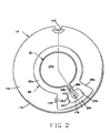
- substrate 16 of transducer 12 has an electrically conductive, generally circular detect plate 22a centrally disposed on a first or inner face surface 16a by any suitable means, as by screen printing, and an electrically conductive trace 22b extending radially outwardly to a detect pin receiving aperture 16b disposed intermediate the detect plate and the outer periphery 16c of the generally circular substrate.
- An electrically conductive detect guard plate 30 is disposed on face surface 16a comprising a first generally discontinuous annulus portion 30a having opposed ends 30b adjacent to and spaced from detect trace 22b.
- a second detect guard portion 30c extends radially outwardly from a location 30d adjacent each opposed end 30b to a location contiguous to and surrounding guard pin aperture 16d and spaced from the detect pin aperture 16b and joined together at 30e at a location radially beyond pin aperture 16b so that a closed opening 30f is formed extending around the detect trace and pin aperture.
- devices made in accordance with the invention have a detect plate 22a formed with a radius of 3,8 mm (0.150 inch), an annulus guard portion with an inner radius of 0.160 inch and an outer radius of 5.95 mm (0.235 inch). Opposed ends 30b are formed with an outer radius of 6,75 mm (0.265 inch). Pin apertures 16b, 16d and a source pin aperture 16e are spaced at 25 degrees apart at a radius of 7,6 mm (0.300 inch). It will also be noted the substrate 16 is formed with a registration notch 16f.
- diaphragm 14 of the transducer has an electrically conductive, generally circular source plate 20a centrally disposed on a first or inner surface 14a by any suitable means, as by screen printing, and an electrically conductive trace 20b extending radially outwardly to a source pin site 14b disposed intermediate the source plate and the outer periphery 14c of the generally circular diaphragm matching the outer periphery of substrate 16.
- An electrically conductive source guard plate 28 is disposed on face surface 14a comprising a first generally discontinuous annulus portion 28a having opposed ends 28b adjacent to and spaced from source trace 20b.
- a second source guard portion 28c extends radially outwardly from a location 28d adjacent each opposed end 28b to a location contiguous to and surrounding ground pin site 14d and spaced from the source pin site 14b and joined together at 28e at a location radially beyond the pin site 14b so that a closed opening 28f is formed extending around the source trace and pin site.
- Conventional source plates where no guard is provided typically have a radius approximately as large as the outer radius of the detect guard annulus.
- the radius of source plate 20 is 4,3 mm (0.170 inch), intermediate the inner and outer radii of the detect guard annulus and somewhat larger than that of the detect plate described above.
- the inner and outer radii of the discontinuous annulus portion 28a is 4,55 mm (0.180 inch) and 5,95 mm (0.235 inch), respectively.
- the outer radius of opposed ends 28b is 6,75 mm (0.265 inch), the same as opposed ends 30b of the detect guard.
- Registration notch 14f is provided in the outer periphery in the same manner as notch 16f of substrate 16.
- a source guard plate surrounding the source plate, source trace and source pin aperture on the first face surface of the diaphragm as well as a detect guard plate surrounding the detect plate, detect trace and detect pin aperture on the first face surface of the substrate essentially eliminates pressure transducer output error due to the presence of polar or conductive fluids.
- Fig. 5 shows a diaphragm 14' having a modified source guard 28' in which the outer radius of opposed end portions 28b' is the same as the remainder of the generally discontinuous annular portion, i.e. 5,95 mm, (0.235 inch), the radially extending second portion 28c' is in the form of a trace having essentially the same width as that of trace 20b.
- the smaller outer radius of opposed ends 28b' in combination with glass annulus 18 provides glass material extending radially outwardly beyond the opposed ends to ensure that the respective metals layers on the diaphragm and substrate cannot creep up the edge of the glass into contact with one another.
- Figs. 6 and 7 show another modified metallization pattern of both the diaphragm 14" and the substrate 16".
- Detect trace 22b" and the source trace 20b" are somewhat narrower than in the Figs. 2, 3 embodiment, e.g, 0,2 mm (0.008 inch) as opposed to 0,5 mm (0.020 inch) and second guard portions 30c" and 28c" are formed with a generally circular opening 30f'' and 28f'' which blend with the outer radii 30g, 28g of opposed ends 30b'', 28b" of the discontinuous annulus.
- Radii 30g, 28g are preferably equal to one another and are selected so that the inside radius 18d of glass annulus 18 is slightly less so that the glass layer 18e overlaps the guard layers preventing any creeping of the electrically conductive material up the edge of the glass layer and possible shorting with the detect and trace layers.
- First discontinuous annuli 28a'', 30a'' are each provided with a radiused recessed portion 28h, 30h respectively, in radial alignment with the respective guard pin site 14e and guard pin aperture 16e. This feature provides suitable clearance to prevent possible metal migration over the inner portion of glass annulus 18 from contacting a trace layer.
- FIG. 6 and 7 are shown to indicate the relative positions of the inner boundary of glass annulus 18 and detect trace 22b" (Fig. 6) and source trace 20b" (Fig. 7) in the assembled transducer.
- Recessed portion 28h of first discontinuous guard annulus 28a" ensures that even if metal from detect trace 22b" migrates across the edge of glass annulus 18 there is sufficient clearance to prevent contact with guard plate 28''.
- recessed portion 30h of guard plate 30" relative to source trace 20b”.
- Windows 18a, 18b and 18c are formed in glass annulus 18 for alignment with pin apertures 16b, 16d and 16e, respectively and with a selected clearance, e.g. 0,75 mm (0.030 inch) as shown, around the overlap between the detect and source traces and the edge of the glass annulus.
Landscapes
- Chemical & Material Sciences (AREA)
- Engineering & Computer Science (AREA)
- Ceramic Engineering (AREA)
- Physics & Mathematics (AREA)
- General Physics & Mathematics (AREA)
- Measuring Fluid Pressure (AREA)
Claims (5)
- Drucksensor (10) mit einem kapazitiven Druckwandler (12), der ein relativ starres Substrat (16) mit einer Längsachse aufweist, das aus einer elektrisch isolierenden Keramik mit einem äußeren Umfang und einer ersten und einer zweiten gegenüberliegenden Stirnfläche gebildet ist, einer relativ flexiblen Membran (14), die aus einer elektrisch isolierenden Keramik mit einem äußeren Umfang und mit einer ersten und einer zweiten gegenüberliegenden Stirnfläche gebildet ist, wobei die Membran (14) auf dem Substrat (16) in einem Abstand zu diesem aufgenommen ist, wobei die jeweiligen ersten Stirnflächen (14a, 16a) einander zugewandt sind und jeweils dieselbe ausgewählte Winkeldeckung aufweisen, einer Detektorplatte (22a) aus einem elektrisch leitenden Material, die zentral auf der ersten Stirnfläche (16a) des Substrats (16) angeordnet ist, einer Quellstift-, einer Schutzstift- und einer Detektorstift-Aumahmeöffhung (16b, 16d, 16e), die voneinander beabstandet sind, wobei sich jede Öffnung (16b, 16d, 16e) zwischen der ersten und der zweiten Stirnfläche des Substrats (16) an einer Stelle zwischen der Detektorplatte (22a) und dem äußeren Umfang erstreckt, einer elektrisch leitenden Detektorbahn (22b) auf der ersten Stirnfläche (16a) des Substrats (16), die sich von der Detektorplatte (22a) zur Detektorstift-Aufnahmeöffnung (16b) erstreckt, einer elektrisch leitenden Detektorschutzplatte (30) auf dem Substrat (16) mit einem ersten im wesentlichen diskontinuierlichen ringförmigen Teil (30a), welcher einander gegenüberliegende Enden (30b) aufweist, die zur Detektorspur (22b) benachbart und von dieser beabstandet sind, und welcher um die Detektorplatte (22a) herum angeordnet und von dieser beabstandet ist, wobei die Detektorschutzplatte (30) einen zweiten Teil (30c) aufweist, der sich von einer Stelle (30d), angrenzend an die einander gegenüberliegenden Enden (30b) des ringförmigen Teils (30a) der Detektorschutzplatte, radial nach außen zu einer Stelle, die zur Schutzstiftöfmung (16d) benachbart ist, und auf beiden Seiten von und beabstandet von der Detektorbahn (22b) erstreckt und die Detektorstiftöffnung (16b) umgibt und von dieser beabstandet ist,
einer Quellplatte (20a) aus einem elektrisch leitenden Material, die zentral auf der ersten Stirnfläche (14a) der Membran (14) und mit der Detektorplatte (22a) ausgerichtet angeordnet ist, wenn die Membran (14) auf dem Substrat (16) in der ausgewählten Deckung aufgenommen ist, mit Quell-, Schutz- und Detektorstiftstellen (14b, 14d), die auf der ersten Stirnfläche (14a) der Membran (14) an einer Stelle ausgebildet sind, die auf die jeweiligen Quell-, Schutz- und Detektorstiftöfnungen (16b, 16d, 16e) ausgerichtet ist, wenn die Membran (14) auf dem Substrat (16) in der ausgewählten Deckung aufgenommen ist, einer elektrisch leitenden Quellbahn (20b) auf der Membran (14), die sich von der Quellplatte (20a) zur Quellstiftstelle (14b) erstreckt, einer elektrisch leitenden Quellschutzplatte (28) auf der ersten Stirnfläche (14a) der Membran (14) mit einem ersten im wesentlichen diskontinuierlichen ringförmigen Teil (28a), welcher einander gegenüberliegende Enden (28b) aufweist, die zur Quellbahn (20b) benachbart und von dieser getrennt sind, und welcher um die Quellplatte (20a) herum angeordnet und von dieser beabstandet ist, wobei die Quellschutzplatte (28) einen zweiten Teil (28c) aufweist, der sich von einer Stelle (28d), angrenzend an die einander gegenüberliegenden Enden (28b) des ringförmigen Teils (28a) der Quellschutzplatte, radial nach außen zu einer Stelle, die zur Schutzstiftstelle (14d) benachbart ist, und auf beiden Seiten von und beabstandet von der Quellstiftstelle (14b) erstreckt, und
einem elektrisch isolierenden Abstandhalter (18), um die Membran (14) vom Substrat (16) beabstandet zu halten. - Drucksensor nach Anspruch 1, bei welchem der Abstandhalter (18) ein ringförmiger Glasring ist, der zwischen den ersten im wesentlichen diskontinuierlichen ringförmigen Teilen (28a, 30a) und einer radial an den äußeren Umfang angrenzenden Stelle angeordnet ist und offene Teile (18a, 18b, 18c) aufweist, die auf die Quell-, Schutz- und Detektorstift-Aufnahmeöffnungen (14b, 14d, 14e) ausgerichtet sind.
- Drucksensor nach Anspruch 2, bei welchem das Substrat (16) und die Membran (14) im wesentlichen zylindrisch mit zusammenpassenden Außenumfängen sind, die Enden des ersten im wesentlichen diskontinuierlichen ringförmigen Teils (30a) der Detektorplatte und des ringförmigen Teils (28a) der Quellplatte in einem ausgewählten Abstand von der Längeachse des im wesentlichen zylindrischen Substrats (16) und der Membran (14) liegen, und der ringförmige Glasring (18) kreisförmig ist und einen Innendurchmesser hat, der kleiner ist als der ausgewählte Abstand, so daß der ringförmige Glasring (18) die Enden des im wesentlichen diskontinuierlichen ringförmigen Teils (30a) der Detektorplatte und des ringförmigen Teils (28a) der Quellplatte überlappt.
- Drucksensor nach Anspruch 1, welcher ferner ein Gehäuse (46) mit einer Fluidaufnahmeöffnung (46a) umfaßt, wobei der Druckwandler (12) im Gehäuse (46) aufgenommen ist und die Membran (14) zur Fluidaufnahmeöffnung (46a) freiliegt, welcher einen elektrischen Verbindungsstecker (36) umfaßt, der Anschlüsse (40, 42, 44) hält, die am Gehäuse (46) befestigt sind, welcher eine Kammer (38) umfaßt, die zwischen dem Druckwandler (12) und dem Verbindungsstecker (36) ausgebildet ist, und welcher eine elektronische Schaltung (50) umfaßt, die in der Kammer (38) angeordnet ist und mit dem Druckwandler (12) und den Anschlüssen (40, 42, 44) elektrisch verbunden ist.
- Drucksensor nach Anspruch 2, bei welchem der erste diskontinuierliche ringförmige Teil der Detektorschutzplatte (30a) und der Quellschutzplatte (28a) mit einem ausgesparten äußeren Bahnabstandsteil (28h, 30h) in radialer Ausrichtung mit der Schutzstiftöffnung (16e) und der Schutzstiftstelle (14e) ausgebildet ist.
Applications Claiming Priority (2)
| Application Number | Priority Date | Filing Date | Title |
|---|---|---|---|
| US67162 | 1998-04-27 | ||
| US09/067,162 US5959212A (en) | 1998-04-27 | 1998-04-27 | Capacitive pressure transducer having reduced output error |
Publications (3)
| Publication Number | Publication Date |
|---|---|
| EP0953832A2 EP0953832A2 (de) | 1999-11-03 |
| EP0953832A3 EP0953832A3 (de) | 2001-06-27 |
| EP0953832B1 true EP0953832B1 (de) | 2003-07-02 |
Family
ID=22074123
Family Applications (1)
| Application Number | Title | Priority Date | Filing Date |
|---|---|---|---|
| EP99302927A Expired - Lifetime EP0953832B1 (de) | 1998-04-27 | 1999-04-15 | Kapazitiver Druckwandler mit reduziertem Ausgangsfehler |
Country Status (4)
| Country | Link |
|---|---|
| US (1) | US5959212A (de) |
| EP (1) | EP0953832B1 (de) |
| JP (1) | JP4565677B2 (de) |
| DE (1) | DE69909170T2 (de) |
Cited By (1)
| Publication number | Priority date | Publication date | Assignee | Title |
|---|---|---|---|---|
| DE102005038822A1 (de) * | 2005-08-17 | 2007-02-22 | Continental Teves Ag & Co. Ohg | Integrierter Drucksensor mit kapazitivem Messprinzip |
Families Citing this family (4)
| Publication number | Priority date | Publication date | Assignee | Title |
|---|---|---|---|---|
| US7775118B2 (en) * | 2008-04-24 | 2010-08-17 | Custom Sensors & Technologies, Inc. | Sensor element assembly and method |
| CN205449348U (zh) * | 2015-12-24 | 2016-08-10 | 华为技术有限公司 | 传感器装置 |
| CN209326840U (zh) | 2018-12-27 | 2019-08-30 | 热敏碟公司 | 压力传感器及压力变送器 |
| CN109979763B (zh) * | 2019-04-30 | 2021-07-16 | 中国科学院苏州纳米技术与纳米仿生研究所 | 耐折叠型一维纤维状柔性储能器件及其制备方法 |
Family Cites Families (11)
| Publication number | Priority date | Publication date | Assignee | Title |
|---|---|---|---|---|
| US4426673A (en) * | 1976-03-12 | 1984-01-17 | Kavlico Corporation | Capacitive pressure transducer and method of making same |
| US4207604A (en) * | 1976-12-02 | 1980-06-10 | Kavlico Corporation | Capacitive pressure transducer with cut out conductive plate |
| US4158217A (en) * | 1976-12-02 | 1979-06-12 | Kaylico Corporation | Capacitive pressure transducer with improved electrode |
| US4716492A (en) * | 1986-05-05 | 1987-12-29 | Texas Instruments Incorporated | Pressure sensor with improved capacitive pressure transducer |
| JP2514067Y2 (ja) * | 1987-06-29 | 1996-10-16 | 京セラ株式会社 | セラミック製トランスデュ−サ |
| JPH0810156B2 (ja) * | 1988-09-02 | 1996-01-31 | 松下電器産業株式会社 | 重量検出装置 |
| US4875135A (en) * | 1988-12-02 | 1989-10-17 | Texas Instruments Incorporated | Pressure sensor |
| EP0596711B1 (de) * | 1992-11-06 | 1998-01-21 | Texas Instruments Incorporated | Verfahren zur Herstellung eines kapazitiven Druckwandlers |
| US5436795A (en) * | 1994-03-28 | 1995-07-25 | Texas Instruments Incorporated | Pressure transducer apparatus and method for making same |
| JPH0961273A (ja) * | 1995-08-28 | 1997-03-07 | Hokuriku Electric Ind Co Ltd | 静電容量式圧力センサ |
| US5656780A (en) * | 1996-03-28 | 1997-08-12 | Kavlico Corporation | Capacitive pressure transducer with an integrally formed front housing and flexible diaphragm |
-
1998
- 1998-04-27 US US09/067,162 patent/US5959212A/en not_active Expired - Lifetime
-
1999
- 1999-04-15 DE DE69909170T patent/DE69909170T2/de not_active Expired - Lifetime
- 1999-04-15 EP EP99302927A patent/EP0953832B1/de not_active Expired - Lifetime
- 1999-04-27 JP JP12057599A patent/JP4565677B2/ja not_active Expired - Lifetime
Cited By (1)
| Publication number | Priority date | Publication date | Assignee | Title |
|---|---|---|---|---|
| DE102005038822A1 (de) * | 2005-08-17 | 2007-02-22 | Continental Teves Ag & Co. Ohg | Integrierter Drucksensor mit kapazitivem Messprinzip |
Also Published As
| Publication number | Publication date |
|---|---|
| US5959212A (en) | 1999-09-28 |
| JPH11337435A (ja) | 1999-12-10 |
| JP4565677B2 (ja) | 2010-10-20 |
| DE69909170T2 (de) | 2004-05-27 |
| DE69909170D1 (de) | 2003-08-07 |
| EP0953832A2 (de) | 1999-11-03 |
| EP0953832A3 (de) | 2001-06-27 |
Similar Documents
| Publication | Publication Date | Title |
|---|---|---|
| EP0372773B2 (de) | Druckmessfühler mit flexibler gedruckter Schaltung | |
| US5974893A (en) | Combined pressure responsive transducer and temperature sensor apparatus | |
| US7322246B2 (en) | Pressure sensor with pressure translation | |
| US4388668A (en) | Capacitive pressure transducer | |
| EP0003387B1 (de) | Elektromechanischer Druckwandler | |
| US4207604A (en) | Capacitive pressure transducer with cut out conductive plate | |
| CA1300925C (en) | Media isolated differential pressure sensors | |
| US4426673A (en) | Capacitive pressure transducer and method of making same | |
| US5150275A (en) | Capacitive pressure sensor | |
| US4177496A (en) | Capacitive pressure transducer | |
| CA1141185A (en) | Differential pressure transducer | |
| US5396803A (en) | Dual balanced capacitance manometers for suppressing vibration effects | |
| US4204244A (en) | Electromechanical pressure transducer | |
| GB1563894A (en) | Capacitive pressure transducer and method for making same | |
| RU2634089C2 (ru) | Датчик давления | |
| US4680971A (en) | Dual diaphragm differential pressure transducer | |
| US4974117A (en) | Dual diaphragm capacitive differential pressure transducer | |
| US4722227A (en) | High pressure sensor | |
| US6223603B1 (en) | Capacitive pressure transducer having reduced output error | |
| US4775850A (en) | Thick-film sensor, particularly a pressure sensor | |
| EP0953832B1 (de) | Kapazitiver Druckwandler mit reduziertem Ausgangsfehler | |
| US6148674A (en) | Shielded capacitive pressure sensor | |
| US5034848A (en) | Low pressure sensor | |
| US6612180B1 (en) | Dielectrically isolated plastic pressure transducer | |
| US6919521B2 (en) | Pressure sensor |
Legal Events
| Date | Code | Title | Description |
|---|---|---|---|
| PUAI | Public reference made under article 153(3) epc to a published international application that has entered the european phase |
Free format text: ORIGINAL CODE: 0009012 |
|
| AK | Designated contracting states |
Kind code of ref document: A2 Designated state(s): DE FR GB IT NL |
|
| AX | Request for extension of the european patent |
Free format text: AL;LT;LV;MK;RO;SI |
|
| PUAL | Search report despatched |
Free format text: ORIGINAL CODE: 0009013 |
|
| AK | Designated contracting states |
Kind code of ref document: A3 Designated state(s): AT BE CH CY DE DK ES FI FR GB GR IE IT LI LU MC NL PT SE |
|
| AX | Request for extension of the european patent |
Free format text: AL;LT;LV;MK;RO;SI |
|
| RIC1 | Information provided on ipc code assigned before grant |
Free format text: 7G 01L 9/12 A, 7G 01L 9/00 B |
|
| 17P | Request for examination filed |
Effective date: 20010927 |
|
| AKX | Designation fees paid |
Free format text: DE FR GB IT NL |
|
| GRAH | Despatch of communication of intention to grant a patent |
Free format text: ORIGINAL CODE: EPIDOS IGRA |
|
| GRAH | Despatch of communication of intention to grant a patent |
Free format text: ORIGINAL CODE: EPIDOS IGRA |
|
| GRAA | (expected) grant |
Free format text: ORIGINAL CODE: 0009210 |
|
| AK | Designated contracting states |
Designated state(s): DE FR GB IT NL |
|
| PG25 | Lapsed in a contracting state [announced via postgrant information from national office to epo] |
Ref country code: NL Free format text: LAPSE BECAUSE OF FAILURE TO SUBMIT A TRANSLATION OF THE DESCRIPTION OR TO PAY THE FEE WITHIN THE PRESCRIBED TIME-LIMIT Effective date: 20030702 Ref country code: IT Free format text: LAPSE BECAUSE OF FAILURE TO SUBMIT A TRANSLATION OF THE DESCRIPTION OR TO PAY THE FEE WITHIN THE PRESCRIBED TIME-LIMIT;WARNING: LAPSES OF ITALIAN PATENTS WITH EFFECTIVE DATE BEFORE 2007 MAY HAVE OCCURRED AT ANY TIME BEFORE 2007. THE CORRECT EFFECTIVE DATE MAY BE DIFFERENT FROM THE ONE RECORDED. Effective date: 20030702 |
|
| REG | Reference to a national code |
Ref country code: GB Ref legal event code: FG4D |
|
| REF | Corresponds to: |
Ref document number: 69909170 Country of ref document: DE Date of ref document: 20030807 Kind code of ref document: P |
|
| NLV1 | Nl: lapsed or annulled due to failure to fulfill the requirements of art. 29p and 29m of the patents act | ||
| ET | Fr: translation filed | ||
| PLBE | No opposition filed within time limit |
Free format text: ORIGINAL CODE: 0009261 |
|
| STAA | Information on the status of an ep patent application or granted ep patent |
Free format text: STATUS: NO OPPOSITION FILED WITHIN TIME LIMIT |
|
| 26N | No opposition filed |
Effective date: 20040405 |
|
| REG | Reference to a national code |
Ref country code: GB Ref legal event code: 732E |
|
| REG | Reference to a national code |
Ref country code: FR Ref legal event code: TP |
|
| PGFP | Annual fee paid to national office [announced via postgrant information from national office to epo] |
Ref country code: FR Payment date: 20110331 Year of fee payment: 13 |
|
| REG | Reference to a national code |
Ref country code: FR Ref legal event code: ST Effective date: 20121228 |
|
| PG25 | Lapsed in a contracting state [announced via postgrant information from national office to epo] |
Ref country code: FR Free format text: LAPSE BECAUSE OF NON-PAYMENT OF DUE FEES Effective date: 20120430 |
|
| PGFP | Annual fee paid to national office [announced via postgrant information from national office to epo] |
Ref country code: GB Payment date: 20130326 Year of fee payment: 15 |
|
| PGFP | Annual fee paid to national office [announced via postgrant information from national office to epo] |
Ref country code: DE Payment date: 20130430 Year of fee payment: 15 |
|
| REG | Reference to a national code |
Ref country code: DE Ref legal event code: R119 Ref document number: 69909170 Country of ref document: DE |
|
| GBPC | Gb: european patent ceased through non-payment of renewal fee |
Effective date: 20140415 |
|
| PG25 | Lapsed in a contracting state [announced via postgrant information from national office to epo] |
Ref country code: DE Free format text: LAPSE BECAUSE OF NON-PAYMENT OF DUE FEES Effective date: 20141101 Ref country code: GB Free format text: LAPSE BECAUSE OF NON-PAYMENT OF DUE FEES Effective date: 20140415 |
|
| REG | Reference to a national code |
Ref country code: DE Ref legal event code: R119 Ref document number: 69909170 Country of ref document: DE Effective date: 20141101 |