EP0953752A2 - Method for avoiding jolts during accelerations of motor vehicles - Google Patents
Method for avoiding jolts during accelerations of motor vehicles Download PDFInfo
- Publication number
- EP0953752A2 EP0953752A2 EP99105534A EP99105534A EP0953752A2 EP 0953752 A2 EP0953752 A2 EP 0953752A2 EP 99105534 A EP99105534 A EP 99105534A EP 99105534 A EP99105534 A EP 99105534A EP 0953752 A2 EP0953752 A2 EP 0953752A2
- Authority
- EP
- European Patent Office
- Prior art keywords
- local
- local minimum
- max
- torque
- maximum
- Prior art date
- Legal status (The legal status is an assumption and is not a legal conclusion. Google has not performed a legal analysis and makes no representation as to the accuracy of the status listed.)
- Withdrawn
Links
Images
Classifications
-
- F—MECHANICAL ENGINEERING; LIGHTING; HEATING; WEAPONS; BLASTING
- F02—COMBUSTION ENGINES; HOT-GAS OR COMBUSTION-PRODUCT ENGINE PLANTS
- F02D—CONTROLLING COMBUSTION ENGINES
- F02D41/00—Electrical control of supply of combustible mixture or its constituents
- F02D41/02—Circuit arrangements for generating control signals
- F02D41/14—Introducing closed-loop corrections
- F02D41/1497—With detection of the mechanical response of the engine
- F02D41/1498—With detection of the mechanical response of the engine measuring engine roughness
-
- F—MECHANICAL ENGINEERING; LIGHTING; HEATING; WEAPONS; BLASTING
- F02—COMBUSTION ENGINES; HOT-GAS OR COMBUSTION-PRODUCT ENGINE PLANTS
- F02D—CONTROLLING COMBUSTION ENGINES
- F02D11/00—Arrangements for, or adaptations to, non-automatic engine control initiation means, e.g. operator initiated
- F02D11/06—Arrangements for, or adaptations to, non-automatic engine control initiation means, e.g. operator initiated characterised by non-mechanical control linkages, e.g. fluid control linkages or by control linkages with power drive or assistance
- F02D11/10—Arrangements for, or adaptations to, non-automatic engine control initiation means, e.g. operator initiated characterised by non-mechanical control linkages, e.g. fluid control linkages or by control linkages with power drive or assistance of the electric type
- F02D11/105—Arrangements for, or adaptations to, non-automatic engine control initiation means, e.g. operator initiated characterised by non-mechanical control linkages, e.g. fluid control linkages or by control linkages with power drive or assistance of the electric type characterised by the function converting demand to actuation, e.g. a map indicating relations between an accelerator pedal position and throttle valve opening or target engine torque
-
- F—MECHANICAL ENGINEERING; LIGHTING; HEATING; WEAPONS; BLASTING
- F02—COMBUSTION ENGINES; HOT-GAS OR COMBUSTION-PRODUCT ENGINE PLANTS
- F02D—CONTROLLING COMBUSTION ENGINES
- F02D41/00—Electrical control of supply of combustible mixture or its constituents
- F02D41/02—Circuit arrangements for generating control signals
- F02D41/04—Introducing corrections for particular operating conditions
- F02D41/10—Introducing corrections for particular operating conditions for acceleration
-
- F—MECHANICAL ENGINEERING; LIGHTING; HEATING; WEAPONS; BLASTING
- F02—COMBUSTION ENGINES; HOT-GAS OR COMBUSTION-PRODUCT ENGINE PLANTS
- F02D—CONTROLLING COMBUSTION ENGINES
- F02D2200/00—Input parameters for engine control
- F02D2200/02—Input parameters for engine control the parameters being related to the engine
- F02D2200/10—Parameters related to the engine output, e.g. engine torque or engine speed
- F02D2200/1015—Engines misfires
-
- F—MECHANICAL ENGINEERING; LIGHTING; HEATING; WEAPONS; BLASTING
- F02—COMBUSTION ENGINES; HOT-GAS OR COMBUSTION-PRODUCT ENGINE PLANTS
- F02D—CONTROLLING COMBUSTION ENGINES
- F02D2250/00—Engine control related to specific problems or objectives
- F02D2250/18—Control of the engine output torque
- F02D2250/21—Control of the engine output torque during a transition between engine operation modes or states
Abstract
Bei einem Verfahren zur Vermeidung von Ruckelschwingungen beim Beschleunigen von Kraftfahrzeugen wird das Motormoment verändert. Um Ruckelschwingungen ohne Beeinträchtigung des Beschleunigungsverhaltens und des Abgasverhaltens zuverlässig zu verhindern, ist vorgesehen, daß bei Betätigung des Fahrpedals das Motormoment gemäß einem vorgegebenen Motor-Momentenverlauf zwischen einem unteren Momentenwert und einem oberen Momentenwert verändert wird, wobei der Motor-Momentenverlauf benachbart zum unteren Momentenwert ein lokales Maximum und zwischen dem lokalen Maximum und dem oberen Momentenwert ein lokales Minimum aufweist. <IMAGE>In a method for avoiding jerky vibrations when accelerating motor vehicles, the engine torque is changed. In order to reliably prevent jerky vibrations without impairing the acceleration behavior and the exhaust gas behavior, it is provided that when the accelerator pedal is actuated, the engine torque is changed between a lower torque value and an upper torque value in accordance with a predetermined engine torque curve, the engine torque curve being adjacent to the lower torque value has a local maximum and a local minimum between the local maximum and the upper torque value. <IMAGE>
Description
Die Erfindung betrifft ein Verfahren zur Vermeidung von Ruckelschwingungen beim Beschleunigen von Kraftfahrzeugen nach dem Oberbegriff des Anspruches 1.The invention relates to a method for avoiding jerky vibrations when accelerating motor vehicles after Preamble of claim 1.
Ruckelschwingungen sind Fahrzeug-Längsschwingungen, die durch Energieeinleitung, insbesondere beim Beschleunigungen des Fahrzeugs, in das Schwingungssystem Motor-Triebstrang-Karosse erzeugt werden. Das Motormoment wird über ein Schwungrad auf den Triebstrang übertragen, der wie eine Torsionsfeder wirkt und unter dem Einfluß des Motormoments zunächst verspannt werden muß. Erfolgt dies durch einen schnellen Momentenaufbau, so kommt es aufgrund der im Schwungrad gespeicherten kinetischen Energie zum Überschwingen des Schwungrades, was sich in der oben genannten Kategorie der Ruckelschwingungen äußert.Jerky vibrations are longitudinal vehicle vibrations caused by Introduction of energy, especially when accelerating the vehicle, generated in the engine-drive train-body vibration system become. The engine torque is transferred to the via a flywheel Drive train that acts like a torsion spring and are initially braced under the influence of the engine torque got to. If this is done by building up moments quickly, so it happens due to the kinetic stored in the flywheel Energy to overshoot the flywheel, which is in the above-mentioned category of jerky vibrations.
Aus der DE 40 13 943 C2 ist es bekannt, Ruckelschwingungen zu verhindern, indem das Motormoment durch eine geregelte Kraftstoffeinspritzung in Abhängigkeit der Schwingungsdauer der Rukkelschwingung beeinflußt wird. Durch eine gezielte Rücknahme bzw. Erhöhung des Motormoments in den entsprechenden Phasen der Ruckelschwingung wird versucht, die durch das Ruckeln verursachten Längsbewegungen zu vermeiden.From DE 40 13 943 C2 it is known to jerky vibrations prevent by the engine torque through a regulated fuel injection depending on the oscillation period of the rocking oscillation being affected. Through a targeted withdrawal or increase the engine torque in the corresponding phases of Jerking vibration is attempted, which is caused by the jerking Avoid longitudinal movements.
Das aus der DE 40 13 943 C2 bekannte Verfahren setzt voraus, daß zunächst die Schwingungsperiode der Ruckelschwingung erfaßt wird. Anschließend wird der Motor-Momentenverlauf über die Kraftstoffeinspritzung in Gegenphase zur Ruckelschwingung beeinflußt. Diese Vorgehensweise hat den Nachteil, daß zur Erfassung der Schwingungsperiode zunächst die erste Ruckelschwingung, die die höchste Amplitude aufweist, abgewartet werden muß, bevor die ruckeldämpfenden Maßnahmen ergriffen werden können, so daß der Fahrkomfort nicht in dem erwünschten Maße verbessert wird. Ein weiterer Nachteil liegt darin, daß der Momentenverlauf der Ruckelbewegung gegengesteuert wird, was ein rasch aufeinanderfolgendes Anschwellen und Abfallen des Motormoments erforderlich macht. Diese mehrfache Momentenrücknahme beeinträchtigt die Grundbeschleunigung des Fahrzeugs und verschlechtert das Abgasverhalten der Brennkraftmaschine.The method known from DE 40 13 943 C2 requires that first the period of vibration of the jerky vibration is detected becomes. Then the engine torque curve over the Fuel injection in the opposite phase to the jerky vibration. This procedure has the disadvantage that it is used for recording the first period of the jerky vibration, which has the highest amplitude can be waited for must be taken before the anti-jerking measures can be taken so that driving comfort is not improved to the desired extent becomes. Another disadvantage is that the torque curve the jerk movement is counteracted, what a rapidly increasing and decreasing engine torque makes necessary. This multiple withdrawal of moments affects the basic acceleration of the vehicle and deteriorates the exhaust gas behavior of the internal combustion engine.
Aus der DE 37 38 719 C2 ist darüberhinaus ein Verfahren zur Verhinderung störender Lastwechselschläge bei einer Fahrzeug-Brennkraftmaschine bekannt. Gemäß dem aus dieser Druckschrift bekannten Verfahren soll zur Vermeidung von Fahrzeug-Längsschwingungen der vom Fahrer über das Gaspedal gegebene Stellbefehl für ein Leistungsstellglied verzögert übertragen werden, wobei die Verzögerung auf den Bereich des Nulldurchgangs des Drehmomentverlaufs begrenzt wird. Bei abrupten Laständerungen wird der Fahrerwunsch verzögert auf die Motorsteuerung übertragen.DE 37 38 719 C2 also describes a method for Prevention of disturbing load changes in a vehicle internal combustion engine known. According to the from this document Known methods are intended to avoid longitudinal vehicle vibrations the one given by the driver via the accelerator pedal Control command for a power actuator transmitted with a delay be, the delay to the area of zero crossing the torque curve is limited. With sudden load changes the driver's request is delayed to the engine control transfer.
Das aus der DE 37 38 719 C2 bekannte Verfahren eignet sich aufgrund des Eingriffs im Bereich des Nulldurchgangs des Drehmomentverlaufs nur zur Minimierung von Lastwechselschlägen, nicht jedoch zur Vermeidung von Ruckelschwingungen, welche üblicherweise im ausschließlich positiven oder ausschließlich negativen Momentenbereich ohne Nulldurchlauf auftreten.The method known from DE 37 38 719 C2 is suitable on the basis of the intervention in the area of the zero crossing of the torque curve only to minimize load changes, not however, to avoid jerky vibrations, which usually im exclusively positive or exclusively negative Torque range without zero crossing occur.
Der Erfindung liegt das Problem zugrunde, Ruckelschwingungen ohne Beeinträchtigung des Beschleunigungsverhaltens und des Abgasverhaltens zuverlässig zu verhindern. The invention is based on the problem of jerky vibrations without impairing the acceleration behavior and the exhaust gas behavior reliably prevent.
Dieses Problem wird erfindungsgemäß mit den Merkmalen des Anspruches 1 gelöst.This problem is solved according to the invention with the features of the claim 1 solved.
Der Momentenverlauf wird in zwei Abschnitte zwischen dem unteren Momentenwert und dem oberen Momentenwert unterteilt: einen ersten, sich an den unteren Momentenwert anschließenden Abschnitt mit dem lokalen Maximum und einen zweiten, dem oberen Momentenwert benachbarten Abschnitt mit dem lokalen Minimum. Im ersten Abschnitt wird der Triebstrang, ausgehend vom unteren Momentenwert, zunächst im lokalen Maximum mit einem definierten Momentenimpuls bzw. einer ersten Treppenstufe vorgespannt. Im zweiten Abschnitt sinkt das Moment auf das lokale Minimum. Das Motormoment wird noch während des Aufschwingens des Triebstrangs vom lokalen Momentenmaximum auf das lokale Momentenminimum reduziert; aufgrund der Trägheit des Triebstrangs spannt sich dieser trotz des bereits reduzierten Moments weiter vor. Im Umkehrpunkt der Schwingungsauslenkung erreicht das Motormoment ausgehend vom lokalen Minimum den oberen Momentenwert. Der Triebstrang ist dadurch im Augenblick des Aufbringens des oberen Momentenwerts statisch vorgespannt und es treten keine bzw. nur stark verminderte Ruckelschwingungen auf.The moment curve is divided into two sections between the lower one Torque value and the upper torque value divided: one first section following the lower torque value with the local maximum and a second, the upper one Moment value adjacent section with the local minimum. in the The first section becomes the drive train, starting from the lower one Torque value, initially in the local maximum with a defined one Torque impulse or biased a first step. in the second section, the moment drops to the local minimum. The Engine torque is still while the drive train is swinging up from the local torque maximum to the local torque minimum reduced; due to the inertia of the drive train despite the already reduced moment. The engine torque reaches the reversal point of the vibration deflection starting from the local minimum, the upper moment value. Of the Drivetrain is thereby at the moment of applying the upper one Torque value statically pre-stressed and no or only strongly reduced jerky vibrations.
Ein weiterer Vorteil liegt darin, daß die Beschleunigung des Fahrzeugs nahezu in gleicher Weise wie bei einer Momenten-Sprungfunktion aufgebaut wird, wodurch eine hohe Agilität erreicht wird, jedoch ohne die bei einer Sprungfunktion auftretenden Ruckelschwingungen.Another advantage is that the acceleration of the Vehicle almost in the same way as with a torque jump function is built up, which achieves a high level of agility but without those that occur with a step function Jerky vibrations.
In zweckmäßiger Weiterbildung beträgt die Zeitspanne zwischen dem unteren Momentenwert - im Falle einer positiven Fahrzeugbeschleunigung der Ausgangswert - und dem oberen Momentenwert - der Zielwert - etwa 1/4 bis 1/2 der Schwingungsdauer der Rukkelschwingung, wodurch eine optimale Schwingungskompensation erreicht wird. Diese Zeitspanne variiert in Abhängigkeit der gewählten Funktion des lokalen Maximums und unterteilt sich in eine Periode maximalen und eine Periode minimalen Motormoments. Wird als Schwingungsanregung zur Vorspannung des Antriebsstrangs als lokales Maximum ein Rechteckimpuls in angenäherter Form eines Dirac-Impulses gewählt, kann die gesamte Zeitspanne für das Maximum und das Minimum auf bis 1/4 der Schwingungsdauer der Ruckelschwingung verkürzt werden. Dieser Verlauf hat den Vorteil, daß der Anstieg vom unteren auf den oberen Momentenwert in Kürzestmöglicher Zeit bei Vermeidung von Ruckelschwingungen erreicht wird.In appropriate further training, the time period is between the lower torque value - in the case of positive vehicle acceleration the initial value - and the upper moment value - the target value - about 1/4 to 1/2 of the oscillation period of the rocking vibration, which ensures optimal vibration compensation is achieved. This time period varies depending on the selected function of the local maximum and is divided into one period of maximum and one period of minimum engine torque. Used as vibration excitation to pre-tension the drive train as a local maximum an approximate rectangular pulse Chosen form of a Dirac pulse, the entire time span for the maximum and the minimum up to 1/4 of the oscillation period the jerky vibration can be shortened. This course has the Advantage that the increase from the lower to the upper torque value in the shortest possible time while avoiding jerky vibrations is achieved.
Das sich an das lokale Maximum anschließende lokale Minimum kann ebenfalls einen rechteckförmigen Verlauf aufweisen. Die Amplitude kann einen geringen Wert größer als Null aufweisen oder auch gleich Null sein. The local minimum following the local maximum can also have a rectangular shape. The Amplitude can have a small value greater than zero or be zero.
Wird die Zeitspanne für das lokale Maximum erhöht, so wird bevorzugt zugleich die Amplitude des Maximums verringert. Bei gleichbleibendem Niveau des lokalen Minimums muß gleichzeitig die Dauer des Minimums verkürzt werden. Insgesamt erhöht sich die gesamte Zeitspanne für das Maximum und das Minimum bis maximal auf die Hälfte der Schwingungsdauer der Ruckelschwingung. Diese Ausführung hat den Vorteil, daß es ausreicht, ein geringeres Niveau für das Momentenmaximum aufzubringen; dennoch können Ruckelschwingungen ausgeglichen werden.If the time period for the local maximum is increased, preference is given to at the same time the amplitude of the maximum is reduced. At constant level of local minimum must be simultaneous the duration of the minimum can be shortened. Overall, increases the entire time span for the maximum and the minimum to maximum to half the vibration duration of the bucking vibration. This design has the advantage that it is sufficient to have a smaller one Apply level for maximum torque; still can Jerky vibrations are balanced.
Wird die Zeitspanne für das lokale Maximum bei gleichbleibender Amplitude erhöht, so werden die Amplitude und die Zeitdauer des lokalen Minimums abgesenkt.If the time span for the local maximum remains the same Amplitude increases, so the amplitude and the duration of the local minimums lowered.
Anstelle einer Rechteckfunktion kann auch eine stetige Funktion für den Momentenverlauf gewählt werden. So ist es insbesondere vorteilhaft, zwischen dem Maximum und dem Minimum sowie zwischen dem Minimum und dem oberen Momentenwert jeweils einen rampenförmigen Verlauf mit einem zwischenliegenden punktförmigen Minimum vorzusehen. Die beiden Rampen können unterschiedlich steil ausgebildet werden, wobei insbesondere die Rampe zwischen dem lokalen Minimum und dem oberen Momentenwert steiler ist als die Rampe zwischen dem lokalen Maximum und dem lokalen Minimum.Instead of a rectangular function, a continuous function can also be used can be selected for the torque curve. It is so in particular advantageous between the maximum and the minimum as well as between the minimum and the upper torque value one each ramped course with an intermediate punctiform Minimum. The two ramps can be different be formed steep, in particular the ramp between the local minimum and the upper torque value steeper is the ramp between the local maximum and the local Minimum.
Bei dem stetigen Verlauf treten keine Momentensprünge auf; er kann daher technisch leicht realisiert werden.With the steady course there are no jumps in moment; he can therefore be easily implemented technically.
Weitere Vorteile und zweckmäßige Ausführungsformen sind den weiteren Ansprüchen, der Figurenbeschreibung und den Zeichnungen zu entnehmen. Es zeigen:
- Fig. 1 bis Fig. 3
- verschiedene rechteckförmige Momentenverläufe,
- Fig. 4
- einen rampenförmigen Momentenverlauf.
- 1 to 3
- different rectangular moments,
- Fig. 4
- a ramp-shaped torque curve.
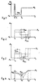
Die in den Fig. 1 bis 4 zeitabhängig dargestellten Motor-Momentenverläufe eignen sich für ein ruckelfreies Beschleunigen eines Kraftfahrzeugs mit Brennkraftmaschine bei zugleich hoher Agilität, d.h. spontanes, verzögerungsfreies Ansprechen und schnelles Aufbringen des Zielmoments. Die Momentenverläufe können bei Beschleunigung des Fahrzeugs von links nach rechts durchfahren werden, wobei das Motormoment ausgehend von einem unteren Motormoment Mu, das das Ausgangsmoment repräsentiert, auf ein oberes Motormoment Mo, das das Zielmoment repräsentiert, erhöht wird. Bei einer Fahrzeugverzögerung werden die Momentenverläufe in entgegengesetzter Richtung von rechts nach links, ausgehend vom oberen Motormoment Mo hin zum unteren Motormoment Mu, durchlaufen.The engine torque curves shown in FIGS. 1 through 4 are suitable for a smooth acceleration of a motor vehicle with an internal combustion engine with high agility at the same time, ie spontaneous, instantaneous response and rapid application of the target torque. The torque curves can be traversed from left to right when the vehicle is accelerating, the engine torque being increased from a lower engine torque M u , which represents the output torque, to an upper engine torque M o , which represents the target torque. In the event of a vehicle deceleration, the torque curves are traversed in the opposite direction from right to left, starting from the upper engine torque M o to the lower engine torque M u .
Im folgenden werden die Schaubilder jeweils am Beispiel eines Beschleunigungsvorgangs beschrieben.In the following the diagrams are based on the example of one Acceleration process described.
Gemäß Fig. 1 beginnt der Beschleunigungsvorgang bei einem unteren Motormoment Mu gleich Null und steigt zum Zeitpunkt t0 sprunghaft auf ein lokales Maximum Mmax an, fällt zum Zeitpunkt t1 sprunghaft auf ein lokales Minimum Mmin, verharrt bis zum Zeitpunkt t2 auf diesem Niveau und steigt schließlich sprunghaft auf das Niveau des oberen Motormoments Mo.1, the acceleration process begins at a lower engine torque M u equal to zero and rises abruptly to a local maximum M max at time t 0, abruptly falls to a local minimum M min at time t 1 , persists until time t 2 this level and finally jumps to the level of the upper engine torque M o .
Fig. 1 stellt einin Extremfall dar, bei dem der Momentenverlauf im Bereich des lokalen Maximums angenähert die Form eines Dirac-Impulses einnimmt, so daß die Dauer des Impulses zwischen t0 und t1 sehr klein ist. Da der Impuls durch das maximal mögliche Motormoment begrenzt ist, wird das lokale Maximum Mmax etwa die Form einer Rechteckfunktion mit begrenzter Amplitude und begrenzter Dauer einnehmen. 1 shows an extreme case in which the torque curve in the area of the local maximum approximately takes the form of a Dirac pulse, so that the duration of the pulse is very short between t 0 and t 1 . Since the pulse is limited by the maximum possible engine torque, the local maximum M max will take the form of a rectangular function with a limited amplitude and a limited duration.
Das untere Ausgangsmoment Mu kann gleich Null sein, aber auch einen von Null abweichenden Wert einnehmen, insbesondere kleiner Null sein, wobei dieser Fall einem Lastwechsel vom Schubbetrieb in den Zugbetrieb entspricht. Das Niveau des lokalen Minimums Mmin kann Null oder größer Null sein. Das Niveau des oberen Zielmoments Mo wird vom Fahrer über die Fahrpedalstellung vorgegeben und ist durch das maximal mögliche Motormoment begrenzt. Das Niveau des lokalen Maximums Mmax kann größer sein als das obere Zielmoment Mo, sofern letzteres kleiner ist als das maximal mögliche Motormoment.The lower output torque M u can be equal to zero, but can also assume a value deviating from zero, in particular less than zero, this case corresponding to a load change from overrun to traction. The level of the local minimum M min can be zero or greater than zero. The level of the upper target torque M o is specified by the driver via the accelerator pedal position and is limited by the maximum possible engine torque. The level of the local maximum M max can be greater than the upper target torque M o , provided that the latter is smaller than the maximum possible engine torque.
Bedingt durch verzögertes Ansprechverhalten einzelner Systemkomponenten können sich gemäß der gestrichelten Darstellung Rampen mit hohem Gradienten zwischen dem unteren Moment Mu und dem lokalen Maximum Mmax, zwischen dem lokalen Maximum Mmax und dem lokalen Minimum Mmin sowie zwischen dem lokalen Minimum Mmin und dem oberen Moment Mo einstellen. Zweckmäßig wird von vornherein ein rampenförmiger Verlauf vorgegeben, so daß ein stetiger Momentenverlauf gegeben ist.Due to the delayed response of individual system components, ramps with a high gradient can occur between the lower moment M u and the local maximum M max , between the local maximum M max and the local minimum M min, and between the local minimum M min and the Set the upper moment M o . A ramp-shaped course is expediently predefined from the outset, so that there is a constant moment course.
Die Zeitspanne t0 bis t2 zwischen dem unteren Motormoment Mu ab Beginn des lokalen Maximums bis zum Erreichen des oberen Motormoments Mo ist auf die Schwingungsdauer der Ruckelschwingung abgestimmt und liegt bei rechteckförmigem Momentenverlauf zweckmäßig zwischen 1/4 und 1/2 der Schwingungsdauer der Rukkelschwingung. Hierdurch wird erreicht, daß der Triebstrang durch das lokale Maximum im Momentenverlauf vorgespannt wird und im Umkehrpunkt der Schwingungsauslenkung das obere Motormoment Mo erreicht wird, wodurch Ruckelschwingungen kompensiert werden.The period of time t 0 to t 2 between the lower engine torque M u from the beginning of the local maximum until the upper engine torque M o is reached is matched to the oscillation period of the bucking vibration and is expediently between 1/4 and 1/2 of the oscillation period in the case of a rectangular torque curve Jerking vibration. This ensures that the drive train is pretensioned by the local maximum in the torque curve and that the upper engine torque M o is reached at the reversal point of the vibration deflection, as a result of which jerky vibrations are compensated for.
Wird wie in Fig. 1 dargestellt ein Rechteckimpuls geringer Dauer und hoher Amplitude als lokales Maximum vorgegeben, kann eine kürzestmögliche Zeitspanne t0 bis t2 für das lokale Maximum und das lokale Minimum von insgesamt 1/4 der Schwingungsdauer der Ruckelschwingung eingestellt werden. Der Übergang vom unteren Motormoment Mu zum oberen Motormoment Mo erfolgt in kürzestmöglicher Zeit.If, as shown in FIG. 1, a rectangular pulse of short duration and high amplitude is specified as the local maximum, the shortest possible time period t 0 to t 2 can be set for the local maximum and the local minimum of a total of 1/4 of the oscillation duration of the jerking vibration. The transition from the lower engine torque M u to the upper engine torque M o takes place in the shortest possible time.
Die Zeitspanne t0 bis t2 erhöht sich, wenn die Amplitude des rechteckförmigen lokalen Maximums verringert wird und sich über eine längere Zeitdauer t0 bis t1 erstreckt. Dadurch ändert sich zugleich das Niveau und die Zeitdauer t1 bis t2 des lokalen Minimums.The time period t 0 to t 2 increases when the amplitude of the rectangular local maximum is reduced and extends over a longer time period t 0 to t 1 . This changes the level and the time period t 1 to t 2 of the local minimum.
Andererseits kann auch das Niveau des lokalen Maximums und das Niveau des lokalen Minimums festgelegt werden, woraus sich die Zeitspannen für das lokale Maximum und das lokale Minimum zwangsweise ergeben.On the other hand, the level of the local maximum and that The level of the local minimum must be determined, which is what the Time periods for the local maximum and the local minimum surrendered.
Fig. 2 zeigt einen modifizierten Verlauf für eine rechteckförmige Momentenfunktion. Gemäß der mit durchgezogener Linie eingetragenen Funktion in Fig. 2 beträgt die Zeitspanne für das lokale Maximum und das lokale Minimum jeweils etwa 1/6 der Schwingungsdauer der Ruckelschwingung, so daß die gesamte Zeitspanne t0 bis t2 für lokales Maximum und lokales Minimum etwa 1/3 der Schwingungsdauer der Ruckelschwingung dauert, wobei diese Verhältnisse insbesondere für die Bedingung gelten, daß das lokale Maximum Mmax das gleiche Momentenniveau wie der obere Momentenwert Mo aufweist.2 shows a modified course for a rectangular torque function. According to the function drawn with a solid line in FIG. 2, the time period for the local maximum and the local minimum is in each case approximately 1/6 of the oscillation duration of the jerky oscillation, so that the entire time period t 0 to t 2 for the local maximum and the local minimum is approximately 1 / 3 of the oscillation duration of the jerky oscillation, these ratios apply in particular to the condition that the local maximum M max has the same torque level as the upper torque value M o .
Gemäß der strichpunktierten Linie in Fig. 2 wird die Zeitspanne t0 bis t1 für das lokale Maximum Mmax bei zugleich geringerer Amplitude verlängert. Dabei verkürzt sich die Dauer des lokalen Minimums zwischen t1 und t2 bei gleichbleibender Höhe des lokalen Minimums. Die gesamte Zeitspanne von t0 bis t2 für lokales Maximum und Minimum ist erhöht. According to the dash-dotted line in FIG. 2, the time period t 0 to t 1 for the local maximum M max is extended with a lower amplitude at the same time. The duration of the local minimum is shortened between t 1 and t 2 while the local minimum remains the same. The total time period from t 0 to t 2 for local maximum and minimum is increased.
Wie in Fig. 2 gestrichelt eingezeichnet, kann das lokale Minimum von einem Wert größer als Null ausgehend erhöht werden. Dabei vergrößert sich die Zeitspanne t1 bis t2. Der obere Momentenwert Mo wird später erreicht und die Zeitspanne t0 bis t1 verringert sich. Das untere Motormoment Mu liegt bei den in Fig. 2 gezeigten Ausführungsbeispielen bei Null.As shown in dashed lines in FIG. 2, the local minimum can be increased starting from a value greater than zero. The time span t 1 to t 2 increases . The upper torque value M o is reached later and the time span t 0 to t 1 is reduced. The lower engine torque M u is zero in the exemplary embodiments shown in FIG. 2.
Fig. 3 zeigt das Motormoment in einer weiteren Ausführung mit rechteckförmigem Verlauf, bei dem ein Lastwechsel von Schubbetrieb auf Zugbetrieb stattfindet. Das untere Motormoment Mu nimmt einen Wert kleiner als Null ein, in diesem Zustand befindet sich der Motor im Schubbetrieb. Zum Zeitpunkt t0 steigt das Motormoment auf das lokale Maximum Mmax, das unterhalb des Niveaus des oberen Motormoments Mo liegt (durchgezogene Linie). Im Zeitpunkt t1 fällt das Moment auf das lokale Minimum Mmin größer Null, verharrt auf diesem Niveau und steigt im Zeitpunkt t2 auf das obere Motormoment Mo.Fig. 3 shows the engine torque in a further embodiment with a rectangular profile, in which a load change takes place from overrun to train operation. The lower engine torque M u takes a value less than zero, in this state the engine is in overrun mode. At time t 0 , the engine torque rises to the local maximum M max , which is below the level of the upper engine torque M o (solid line). At time t 1 , the torque drops to the local minimum M min greater than zero, remains at this level and rises to the upper engine torque M o at time t 2 .
Die Momentendifferenz zwischen dem lokalen Maximum Mmax und dem lokalen Minimum Mmin kann gegebenenfalls stark reduziert werden. Wie in Fig. 3 gestrichelt eingezeichnet, kann das lokale Minimum das gleiche Niveau aufweisen wie das lokale Maximum, so daß sich für den Momentenverlauf zwischen unterem und oberem Motormoment eine zweistufige Treppenfunktion ergibt. In dieser Ausführung verschiebt sich der das Ende des lokalen Minimums markierende Zeitpunkt t2 nach hinten.The torque difference between the local maximum M max and the local minimum M min can optionally be greatly reduced. As shown in dashed lines in FIG. 3, the local minimum can have the same level as the local maximum, so that a two-stage step function results for the torque curve between the lower and upper engine torque. In this embodiment, the time t 2 marking the end of the local minimum shifts to the rear.
Eine weitere Ausführung ist in Fig. 3 mit strichpunktierter Linie eingetragen. Das lokale Maximum Mmax liegt auf einem vergleichsweise höheren Niveau als bei der durchgezogenen Funktion und sinkt im Zeitpunkt t1 früher auf das lokale Minimum Mmin ab, dessen Niveau unterhalb des vergleichbaren Niveaus der durchgezogenen Funktion liegt. Die Zeitspanne t1 bis t2 für die Dauer des lokalen Minimums ist verkürzt, der obere Momentenwert Mo wird früher erreicht.Another embodiment is shown in Fig. 3 with a dash-dotted line. The local maximum M max is at a comparatively higher level than with the solid function and drops earlier at time t 1 to the local minimum M min , the level of which is below the comparable level of the solid function. The time period t 1 to t 2 for the duration of the local minimum is shortened, the upper torque value M o is reached earlier.
Fig. 4 zeigt einen rampenförmigen Momentenverlauf zwischen dem punktförmig ausgebildeten lokalen Maximum Mmax und dem ebenfalls punktförmig ausgebildeten lokalen Minimum Mmin sowie zwischen dem lokalen Minimum und dem oberen Momentenwert Mo, wodurch sich ein V-förmiger Kurvenverlauf zwischen Mmax und Mo ergibt. Das lokale Maximum Mmax liegt bei der mit durchgezogenem Strich eingezeichneten Funktion etwa auf dem Niveau des oberen Momentenwerts Mo, das lokale Minimum Mmin hat einen Wert größer Null. Die Zeitspanne t0 bis t1 für das Absinken des Motormoments von Mmax auf Mmin ist etwa gleich groß wie die Zeitspanne t1 bis t2 für das Ansteigen des Motormoments von Mmin auf Mo.4 shows a ramp-shaped torque curve between the point-shaped local maximum M max and the likewise point-shaped local minimum M min and between the local minimum and the upper moment value M o , which results in a V-shaped curve between M max and M o . The local maximum M max is approximately at the level of the upper moment value M o in the function drawn with a solid line, the local minimum M min has a value greater than zero. The time span t 0 to t 1 for the engine torque to decrease from M max to M min is approximately the same as the time span t 1 to t 2 for the engine torque to increase from M min to M o .
Das lokale Maximum der strichpunktierten Funktion liegt geringfügig unterhalb des Maximums der durchgezogenen Funktion und fällt auf eine tieferes lokales Minimum ab, das zu einem späteren Zeitpunkt t1 erreicht wird. Der rampenförmige Anstieg auf den oberen Momentenwert Mo erfolgt mit einem größeren Gradienten, wobei der obere Momentenwert Mo zu einem früheren Zeitpunkt t2 im Vergleich zur durchgezogenen Funktion erreicht wird.The local maximum of the dash-dotted function lies slightly below the maximum of the continuous function and drops to a lower local minimum, which is reached at a later time t 1 . The ramp-like rise to the upper torque value M o takes place with a larger gradient, the upper torque value M o being reached at an earlier point in time t 2 in comparison to the solid function.
Gemäß einer nicht gezeigten Ausführung kann der obere Momentenwert bei den gleichen zuvor beschriebenen Parametern aber auch später erreicht werden.According to an embodiment not shown, the upper torque value can but also with the same parameters described above can be reached later.
Der mit einer Strich-Doppelpunkt-Linie gekennzeichnete Momentenverlauf beginnt im lokalen Maximum Mmax, dessen Niveau abgesenkt ist, und verläuft in einer flach abfallenden Rampe zum lokalen Minimum Mmin, das zu einem früheren Zeitpunkt t1 erreicht wird. Der rampenförmige Anstieg zum oberen Momentenwert Mo weist einen größeren Gradienten auf als die abfallende Rampe; der obere Momentenwert Mo wird zu einem späteren Zeitpunkt t2 erreicht.The torque curve marked with a dash-colon line begins in the local maximum M max , the level of which is lowered, and runs in a gently sloping ramp to the local minimum M min , which is reached at an earlier point in time t 1 . The ramp-like rise to the upper torque value M o has a larger gradient than the falling ramp; the upper torque value M o is reached at a later time t 2 .
Anstelle eines punktförmigen lokalen Minimums kann es zweckmäßig sein, im lokalen Minimum einen Abschnitt gleichbleibenden Momentenniveaus vorzusehen, wodurch sich ein etwa trapezförmiger Verlauf des lokalen Minimums ergibt.Instead of a punctiform local minimum, it can be useful be a section constant in the local minimum Provide moment levels, which results in an approximately trapezoidal The course of the local minimum results.
Sowohl die rechteckförmigen als auch die V-förmigen Momentenverläufe können durch die Wahl von zwei Parametern festgelegt werden. Bei der Wahl des lokalen Minimums und des lokalen Maximums werden die Zeitpunkte t1 und t2 für das Ende des lokalen Maximums bzw. des lokalen Minimums in engen Grenzen vorbestimmt. Bei der Wahl eines Momentenwerts für Maximum oder Minimum und eines Zeitpunktes werden der jeweils andere Momentenwert bzw. der jeweils andere Zeitpunkt in engen Grenzen vorbestimmt.Both the rectangular and the V-shaped torque profiles can be determined by choosing two parameters. When choosing the local minimum and the local maximum, the times t 1 and t 2 for the end of the local maximum or the local minimum are predetermined within narrow limits. When a moment value is selected for maximum or minimum and a point in time, the other moment value or the other point in time is predetermined within narrow limits.
Wie gestrichelt eingezeichnet, kann es zweckmäßig sein, die Übergänge zwischen den verschiedenen Momentenniveaus geglättet auszuführen, um einen in der ersten und gegebenenfalls auch einen in der zweiten Ableitung stetigen Kurvenverlauf für das Motormoment zu erhalten. Die dargestellten Kurvenverläufe können durch Polynome angenähert werden.As shown in dashed lines, it may be appropriate to Transitions between the different moment levels smoothed to perform one in the first and possibly also one in the second derivative, a steady curve for the engine torque to obtain. The curves shown can can be approximated by polynomials.
Gemäß einer weiteren vorteilhaften, sägezahnähnlichen Ausführung fällt der Momentenverlauf rampenförmig vom lokalen Maximum zum lokalen Minimum ab und steigt im Zeitpunkt t2 sprunghaft auf das Niveau des oberen Momentenwerts Mo. Der Verlauf dieser Funktion wird durch die Parameter Mmax, Mmin und t2 festgelegt, wobei t2 zugleich den Beginn und das Ende des lokalen Minimums markiert. Wird einer der bestimmenden Parameter frei gewählt, werden den beiden anderen Parametern enge Grenzen zur Variation gesetzt. Je größer der Gradient der vom Maximum auf das Minimum abfallenden Rampe, um so niedriger liegt das Niveau des Minimums und um so früher wird der Zeitpunkt t2 erreicht, in dem der sprunghafte Anstieg auf den oberen Momentenwert Mo erfolgt.According to a further advantageous, sawtooth-like design, the torque curve drops in a ramp from the local maximum to the local minimum and rises abruptly at the time t 2 to the level of the upper torque value M o . The course of this function is determined by the parameters M max , M min and t 2 , with t 2 simultaneously marking the beginning and the end of the local minimum. If one of the determining parameters is chosen freely, the other two parameters are set narrow limits for variation. The greater the gradient of the ramp falling from the maximum to the minimum, the lower the level of the minimum and the earlier the time t 2 is reached at which the sudden increase to the upper torque value M o takes place.
Außer den gezeigten Kurvenverläufen können auch beliebige weitere Kurvenverläufe für das Motormoment herangezogen werden, soweit die Bedingung erfüllt ist, daß das Moment ausgehend vom unteren Moment Mu zunächst auf ein lokales Maximum Mmax ansteigt, anschließend auf ein lokales Minimum Mmin abfällt und dann wieder auf das obere Moment Mo ansteigt. Diese Kurvenverläufe können beispielsweise aus Meßpunkten, die gegebenenfalls durch Polynome geglättet werden, gewonnen werden.In addition to the curve profiles shown, any other curve profiles can also be used for the engine torque, provided the condition is met that the torque initially increases from the lower torque M u to a local maximum M max , then drops to a local minimum M min and then again increases to the upper moment M o . These curves can be obtained, for example, from measuring points that may be smoothed by polynomials.
Die Momentenverläufe können in einer Steuer- und Regelungseinheit berechnet bzw. in Speichern der Steuer- und Regelungseinheit abgelegt, in diskreten Schritten abgetastet und als Stellsignal diversen Motorkomponenten zugeführt werden, über die das Motormoment beeinflußt werden kann. Das Motormoment kann beispielsweise über eine Zündwinkelverstellung, eine Zündaussetzung, die Kraftstoffeinspritzung, eine Abgasrückführung oder einen Abgasturbolader oder ähnliches eingestellt werden. Weiterhin ist es möglich, das Motormoment über eine Drosselklappenregelung einzustellen, indem das Stellglied der Drosselklappe zur Erzeugung des lokalen Maximums schlagartig und kurzzeitig geöffnet, anschließend für das lokale Minimum wieder geschlossen und schließlich zum Erreichen des oberen Momentenwerts wieder geöffnet wird.The torque profiles can be in a control and regulation unit calculated or in memory of the control and regulation unit stored, sampled in discrete steps and as a control signal various engine components are supplied, through which the Motor torque can be influenced. The engine torque can, for example via an ignition angle adjustment, an ignition suspension, fuel injection, exhaust gas recirculation or an exhaust gas turbocharger or the like can be set. Farther it is possible to control the engine torque via a throttle valve adjust by the throttle valve actuator to generate the local maximum suddenly and briefly opened, then closed again for the local minimum and finally to reach the upper moment value is opened again.
Claims (20)
dadurch gekennzeichnet,
daß bei Betätigung des Fahrpedals das Motormoment gemäß einem vorgegebenen Motor-Momentenverlauf zwischen einem unteren Momentenwert (Mu) und einem oberen Momentenwert (Mo) verändert wird, wobei der Motor-Momentenverlauf benachbart zum unteren Momentenwert (Mu) ein lokales Maximum (Mmax) und zwischen dem lokalen Maximum (Mmax) und dem oberen Momentenwert (Mo) ein lokales Minimum (Mmin) aufweist.Method for avoiding jerky vibrations when accelerating motor vehicles by changing the engine torque,
characterized,
that when the accelerator pedal is actuated, the engine torque is changed according to a predetermined engine torque curve between a lower torque value (M u ) and an upper torque value (M o ), the engine torque curve adjacent to the lower torque value (M u ) being a local maximum (M max ) and between the local maximum (M max ) and the upper torque value (M o ) has a local minimum (M min ).
dadurch gekennzeichnet,
daß die Zeitspanne zwischen dem unteren Momentenwert (Mu) und dem oberen Momentenwert (Mo) 1/4 bis 1/2 der Schwingungsdauer der Ruckelschwingung beträgt.Method according to claim 1,
characterized,
that the time period between the lower torque value (M u ) and the upper torque value (M o ) is 1/4 to 1/2 of the oscillation period of the bucking vibration.
dadurch gekennzeichnet,
daß die Dauer des lokalen Maximums (Mmax) maximal 1/2 der Schwingungsdauer der Ruckelschwingung beträgt. The method of claim 1 or 2,
characterized,
that the duration of the local maximum (M max ) is a maximum of 1/2 the oscillation duration of the bucking vibration.
dadurch gekennzeichnet,
daß die Dauer des lokalen Minimums (Mmin) maximal 1/4 der Schwingungsdauer der Ruckelschwingung beträgt.Method according to one of claims 1 to 3,
characterized,
that the duration of the local minimum (M min ) is a maximum of 1/4 of the vibration duration of the jerking vibration.
dadurch gekennzeichnet,
daß die Zeitspanne (t1 - t0) zwischen dem lokalen Maximum (Mmax) und dem lokalen Minimum (Mmin) gleich ist wie Zeitspanne (t2 -t1) zwischen dem lokalen Minimum (Mmin) und dem oberen Momentenwert (Mo).Method according to one of claims 1 to 4,
characterized,
that the time span (t 1 - t 0 ) between the local maximum (M max ) and the local minimum (M min ) is the same as the time span (t 2 -t 1 ) between the local minimum (M min ) and the upper moment value ( M o ).
dadurch gekennzeichnet,
daß das lokale Minimum (Mmin) nach 1/4 der Schwingungsdauer der Ruckelschwingung erreicht wird.Method according to claim 5,
characterized,
that the local minimum (M min ) is reached after 1/4 of the oscillation period of the bucking oscillation.
dadurch gekennzeichnet,
daß mit zunehmender Dauer des lokalen Maximums (Mmax) die Amplitude des lokalen Maximums (Mmax) reduziert wird.Method according to one of claims 1 to 6,
characterized by
that with increasing duration of the local maximum (M max ) the amplitude of the local maximum (M max ) is reduced.
dadurch gekennzeichnet,
daß die Amplitude des lokalen Minimums (Mmin) gleich bleibt und die Dauer des lokalen Minimums (Mmin) reduziert wird. Method according to claim 7,
characterized,
that the amplitude of the local minimum (M min ) remains the same and the duration of the local minimum (M min ) is reduced.
dadurch gekennzeichnet,
daß die Gesamtdauer für das lokale Maximum (Mmax) und das lokale Minimum (Mmin) erhöht ist.A method according to claim 8,
characterized,
that the total duration for the local maximum (M max ) and the local minimum (M min ) is increased.
dadurch gekennzeichnet,
daß mit zunehmender Dauer des lokalen Minimums (Mmin) die Amplitude des lokalen Minimums (Mmin) erhöht wird.Method according to one of claims 1 to 6,
characterized,
that with increasing duration of the local minimum (M min ) the amplitude of the local minimum (M min ) is increased.
dadurch gekennzeichnet,
daß die Amplitude des lokalen Maximums (Mmax) gleich bleibt und die Dauer des lokalen Maximums (Mmax) reduziert wird.A method according to claim 10,
characterized,
that the amplitude of the local maximum (M max ) remains the same and the duration of the local maximum (M max ) is reduced.
dadurch gekennzeichnet,
daß die Gesamtdauer für das lokale Maximum (Mmax) und das lokale Minimum (Mmin) erhöht ist.A method according to claim 11,
characterized,
that the total duration for the local maximum (M max ) and the local minimum (M min ) is increased.
dadurch gekennzeichnet,
daß der Momentenverlauf zumindest abschnittsweise eine Rechteckfunktion ist. Method according to one of claims 1 to 12,
characterized,
that the torque curve is a rectangular function at least in sections.
dadurch gekennzeichnet,
daß das lokale Maximum (Mmax) und das lokale Minimum (Mmin) jeweils eine näherungsweise rechteckförmige Stufe der Rechteckfunktion bilden.A method according to claim 13,
characterized,
that the local maximum (M max ) and the local minimum (M min ) each form an approximately rectangular step of the rectangular function.
dadurch gekennzeichnet,
daß der Momentenverlauf zwischen dem lokalen Maximum (Mmax) und dem oberen Momentenwert (Mo) als stetige Funktion ausgebildet ist.Method according to one of claims 1 to 13,
characterized,
that the torque curve between the local maximum (M max ) and the upper torque value (M o ) is designed as a continuous function.
dadurch gekennzeichnet,
daß der Momentenverlauf zwischen dem lokalen Maximum (Mmax) und dem lokalen Minimum (Mmin) rampenförmig ausgebildet ist.Method according to one of claims 1 to 15,
characterized,
that the torque curve between the local maximum (M max ) and the local minimum (M min ) is ramp-shaped.
dadurch gekennzeichnet,
daß der Momentenverlauf zwischen dem lokalen Minimum (Mmin) und dem oberen Momentenwert (Mo) rampenförmig ausgebildet ist.Method according to one of claims 1 to 16,
characterized,
that the torque curve between the local minimum (M min ) and the upper torque value (M o ) is ramp-shaped.
dadurch gekennzeichnet,
daß der Momentenverlauf zwischen dem lokalen Minimum (Mmin) und dem oberen Momentenwert (Mo) sprunghaft ausgebildet ist. Method according to one of claims 1 to 16,
characterized,
that the torque curve between the local minimum (M min ) and the upper torque value (M o ) is erratic.
dadurch gekennzeichnet,
daß das lokale Minimum (Mmin) punktförmig ausgebildet ist.Method according to one of claims 16 to 18,
characterized,
that the local minimum (M min ) is point-shaped.
dadurch gekennzeichnet,
daß das lokale Minimum (Mmin) einen Abschnitt konstanten Momentenniveaus aufweist.Method according to one of claims 16 to 18,
characterized,
that the local minimum (M min ) has a portion of constant moment levels.
Applications Claiming Priority (2)
| Application Number | Priority Date | Filing Date | Title |
|---|---|---|---|
| DE19819050 | 1998-04-29 | ||
| DE19819050A DE19819050C1 (en) | 1998-04-29 | 1998-04-29 | Preventing bucking when accelerating |
Publications (2)
| Publication Number | Publication Date |
|---|---|
| EP0953752A2 true EP0953752A2 (en) | 1999-11-03 |
| EP0953752A3 EP0953752A3 (en) | 2001-04-18 |
Family
ID=7866097
Family Applications (1)
| Application Number | Title | Priority Date | Filing Date |
|---|---|---|---|
| EP99105534A Withdrawn EP0953752A3 (en) | 1998-04-29 | 1999-03-18 | Method for avoiding jolts during accelerations of motor vehicles |
Country Status (4)
| Country | Link |
|---|---|
| US (1) | US6220221B1 (en) |
| EP (1) | EP0953752A3 (en) |
| JP (1) | JPH11350987A (en) |
| DE (1) | DE19819050C1 (en) |
Cited By (1)
| Publication number | Priority date | Publication date | Assignee | Title |
|---|---|---|---|---|
| WO2002103180A1 (en) * | 2001-06-15 | 2002-12-27 | Robert Bosch Gmbh | Method and device for controlling an internal combustion engine |
Families Citing this family (9)
| Publication number | Priority date | Publication date | Assignee | Title |
|---|---|---|---|---|
| DE19958251C2 (en) | 1999-12-03 | 2002-11-21 | Siemens Ag | Method for damping mechanical vibrations in the drive train of an internal combustion engine |
| DE10017281A1 (en) * | 2000-04-06 | 2001-10-11 | Bosch Gmbh Robert | Controlling drive unit involves reducing drive unit output parameter during presence of oscillations in drive train until they decay |
| DE10036282A1 (en) * | 2000-07-26 | 2002-02-07 | Bosch Gmbh Robert | Method and device for controlling a drive unit |
| DE10119724B4 (en) * | 2001-04-21 | 2006-01-19 | Daimlerchrysler Ag | Device for preventing load impacts in the drive train of motor vehicles |
| DE10206197A1 (en) * | 2002-02-15 | 2003-09-04 | Daimler Chrysler Ag | Reducing load change impact for vehicle with sub-frame involves accelerating the sub-frame during acceleration and braking it before it impacts on the body |
| KR100579234B1 (en) * | 2003-09-09 | 2006-05-11 | 현대자동차주식회사 | Torque control method of internal combustion engine |
| DE102005012931B4 (en) * | 2005-03-15 | 2019-01-31 | Volkswagen Ag | Method for controlling a moment structure of a hybrid vehicle and hybrid vehicle |
| JP4743057B2 (en) * | 2006-09-12 | 2011-08-10 | トヨタ自動車株式会社 | Throttle opening control device for internal combustion engine |
| US8041500B2 (en) | 2010-04-08 | 2011-10-18 | Ford Global Technologies, Llc | Reformate control via accelerometer |
Citations (2)
| Publication number | Priority date | Publication date | Assignee | Title |
|---|---|---|---|---|
| DE4013943C2 (en) | 1989-05-01 | 1992-12-10 | Toyota Jidosha K.K., Toyota, Aichi, Jp | |
| DE3738719C2 (en) | 1986-11-27 | 1997-09-25 | Volkswagen Ag | Method and arrangement for preventing disturbing load changes in a vehicle internal combustion engine |
Family Cites Families (15)
| Publication number | Priority date | Publication date | Assignee | Title |
|---|---|---|---|---|
| DE3209463A1 (en) * | 1982-03-16 | 1983-09-29 | Dr.Ing.H.C. F. Porsche Ag, 7000 Stuttgart | CIRCUIT ARRANGEMENT FOR ACTUATING THE THROTTLE VALVE OF A MOTOR VEHICLE INTERNAL COMBUSTION ENGINE |
| DE3621555A1 (en) * | 1986-06-27 | 1988-01-07 | Hella Kg Hueck & Co | DEVICE FOR ADJUSTING THE SPEED OF A MOTOR VEHICLE |
| US4844026A (en) * | 1987-03-25 | 1989-07-04 | Japan Electronic Control Systems Company, Limited | Spark ignition timing control system for internal combustion engine with feature of suppression of jerking during engine acceleration |
| JP2701270B2 (en) * | 1987-11-05 | 1998-01-21 | 株式会社日立製作所 | Ignition advance control device |
| JPH0379371A (en) | 1989-08-24 | 1991-04-04 | Nakajima All Purishijiyon Kk | Printing control circuit |
| JP2517289Y2 (en) * | 1989-09-12 | 1996-11-20 | 本田技研工業 株式会社 | Ignition timing control device for internal combustion engine |
| JP2861225B2 (en) * | 1990-03-26 | 1999-02-24 | 株式会社デンソー | Control device for vehicle internal combustion engine system |
| DE4202407C2 (en) | 1992-01-29 | 1994-02-03 | Daimler Benz Ag | Procedure for damping longitudinal vibrations |
| JPH05296097A (en) | 1992-04-21 | 1993-11-09 | Mitsubishi Electric Corp | Intake air quantity controller of engine |
| DE4223520C2 (en) | 1992-07-17 | 2001-05-17 | Bosch Gmbh Robert | Control system for the fuel metering of an internal combustion engine |
| US5532929A (en) | 1992-12-16 | 1996-07-02 | Toyota Jidosha Kabushiki Kaisha | Apparatus for controlling vehicle driving power |
| JP2849322B2 (en) * | 1993-12-16 | 1999-01-20 | 三菱自動車工業株式会社 | Engine fuel injection control device |
| DE19534633A1 (en) * | 1995-05-30 | 1996-12-05 | Bosch Gmbh Robert | Throttle control for vehicle IC engine |
| JP2742900B2 (en) | 1995-11-17 | 1998-04-22 | 日東精工株式会社 | Rivet caulking machine |
| US5963216A (en) | 1996-04-25 | 1999-10-05 | Hewlett-Packard Company | Providing print preview of a print job using printing calls from a print driver |
-
1998
- 1998-04-29 DE DE19819050A patent/DE19819050C1/en not_active Expired - Fee Related
-
1999
- 1999-03-18 EP EP99105534A patent/EP0953752A3/en not_active Withdrawn
- 1999-04-28 JP JP11158447A patent/JPH11350987A/en active Pending
- 1999-04-29 US US09/302,124 patent/US6220221B1/en not_active Expired - Lifetime
Patent Citations (2)
| Publication number | Priority date | Publication date | Assignee | Title |
|---|---|---|---|---|
| DE3738719C2 (en) | 1986-11-27 | 1997-09-25 | Volkswagen Ag | Method and arrangement for preventing disturbing load changes in a vehicle internal combustion engine |
| DE4013943C2 (en) | 1989-05-01 | 1992-12-10 | Toyota Jidosha K.K., Toyota, Aichi, Jp |
Cited By (1)
| Publication number | Priority date | Publication date | Assignee | Title |
|---|---|---|---|---|
| WO2002103180A1 (en) * | 2001-06-15 | 2002-12-27 | Robert Bosch Gmbh | Method and device for controlling an internal combustion engine |
Also Published As
| Publication number | Publication date |
|---|---|
| JPH11350987A (en) | 1999-12-21 |
| EP0953752A3 (en) | 2001-04-18 |
| DE19819050C1 (en) | 1999-10-14 |
| US6220221B1 (en) | 2001-04-24 |
Similar Documents
| Publication | Publication Date | Title |
|---|---|---|
| DE102006000431B4 (en) | Cruise control device and method for vehicles | |
| EP2798180B1 (en) | Control method of an internal combustion to avoid a too frequent hunting between at least two combustion modes | |
| EP0760056B1 (en) | Process and device for controlling an internal combustion engine | |
| DE102007035089B4 (en) | Throttle opening control system and method for an internal combustion engine | |
| EP1203270B1 (en) | Method and device for reducing torsional vibrations in an internal combustion engine | |
| DE19501299B4 (en) | Method and device for controlling an internal combustion engine of a vehicle | |
| EP0953752A2 (en) | Method for avoiding jolts during accelerations of motor vehicles | |
| DE102013001043B3 (en) | Method for operating combustion engine of motor car, involves determining target compression ratio by expected size estimation operating variable estimated based on current gradient of operating parameter over time, in prediction mode | |
| EP1028242B1 (en) | Method and apparatus for damping vibration type vehicle movements | |
| DE10024704A1 (en) | Method of controlling vehicle engine during clutch operations, increases e.g. engine speed | |
| EP1613852B1 (en) | Method for operating an internal combustion engine comprising torque monitoring | |
| EP1537312B1 (en) | Method and device for controlling the drive unit of a vehicle | |
| DE102004025741A1 (en) | Driving motor vehicle with speed or spacer control and automatic machine gearbox involves controlling drive operation of motor vehicle based on current travel speed and given target travel speed of vehicle using control system with computer | |
| DE19838454C1 (en) | Process for reducing load change shock in motor vehicles | |
| DE102005042650B4 (en) | Speed control for an internal combustion engine in the event of a fall in gas | |
| EP0953753A2 (en) | Method for avoiding jolts when accelerating motor vehicles | |
| DE19739827B4 (en) | Method and device for controlling an operating variable of a motor vehicle | |
| EP0894961A2 (en) | Method for suppressing longitidinal oscillations during positive and negative accelerations of motor vehicles | |
| EP1276979B1 (en) | Method and device for controlling a drive unit of a vehicle | |
| DE19949449B4 (en) | Method for damping jerky vibrations | |
| DE102017219785A1 (en) | Method for controlling a speed of an internal combustion engine with compensation of a dead time | |
| DE19547716B4 (en) | Method and device for controlling or limiting the speed of a vehicle | |
| DE10243342B3 (en) | Method and device for lambda control in an internal combustion engine with a closed lambda control loop | |
| EP1281853B1 (en) | Method and device for controlling a drive unit of a vehicle | |
| DE102005059689A1 (en) | Controlling method for a motor vehicle engine's load uses a desired load signal from a driver to adjust desired load on an engine linked to acceleration |
Legal Events
| Date | Code | Title | Description |
|---|---|---|---|
| PUAI | Public reference made under article 153(3) epc to a published international application that has entered the european phase |
Free format text: ORIGINAL CODE: 0009012 |
|
| AK | Designated contracting states |
Kind code of ref document: A2 Designated state(s): DE ES FR GB IT |
|
| AX | Request for extension of the european patent |
Free format text: AL;LT;LV;MK;RO;SI |
|
| PUAL | Search report despatched |
Free format text: ORIGINAL CODE: 0009013 |
|
| AK | Designated contracting states |
Kind code of ref document: A3 Designated state(s): AT BE CH CY DE DK ES FI FR GB GR IE IT LI LU MC NL PT SE |
|
| AX | Request for extension of the european patent |
Free format text: AL;LT;LV;MK;RO;SI |
|
| AKX | Designation fees paid |
Free format text: DE ES FR GB IT |
|
| STAA | Information on the status of an ep patent application or granted ep patent |
Free format text: STATUS: THE APPLICATION IS DEEMED TO BE WITHDRAWN |
|
| 18D | Application deemed to be withdrawn |
Effective date: 20011019 |