EP0953536B1 - Schlauchhaspel - Google Patents
Schlauchhaspel Download PDFInfo
- Publication number
- EP0953536B1 EP0953536B1 EP99201166A EP99201166A EP0953536B1 EP 0953536 B1 EP0953536 B1 EP 0953536B1 EP 99201166 A EP99201166 A EP 99201166A EP 99201166 A EP99201166 A EP 99201166A EP 0953536 B1 EP0953536 B1 EP 0953536B1
- Authority
- EP
- European Patent Office
- Prior art keywords
- hose
- reel
- hose reel
- improved
- extremity
- Prior art date
- Legal status (The legal status is an assumption and is not a legal conclusion. Google has not performed a legal analysis and makes no representation as to the accuracy of the status listed.)
- Expired - Lifetime
Links
Images

Classifications
-
- B—PERFORMING OPERATIONS; TRANSPORTING
- B65—CONVEYING; PACKING; STORING; HANDLING THIN OR FILAMENTARY MATERIAL
- B65H—HANDLING THIN OR FILAMENTARY MATERIAL, e.g. SHEETS, WEBS, CABLES
- B65H75/00—Storing webs, tapes, or filamentary material, e.g. on reels
- B65H75/02—Cores, formers, supports, or holders for coiled, wound, or folded material, e.g. reels, spindles, bobbins, cop tubes, cans, mandrels or chucks
- B65H75/34—Cores, formers, supports, or holders for coiled, wound, or folded material, e.g. reels, spindles, bobbins, cop tubes, cans, mandrels or chucks specially adapted or mounted for storing and repeatedly paying-out and re-storing lengths of material provided for particular purposes, e.g. anchored hoses, power cables
- B65H75/38—Cores, formers, supports, or holders for coiled, wound, or folded material, e.g. reels, spindles, bobbins, cop tubes, cans, mandrels or chucks specially adapted or mounted for storing and repeatedly paying-out and re-storing lengths of material provided for particular purposes, e.g. anchored hoses, power cables involving the use of a core or former internal to, and supporting, a stored package of material
- B65H75/44—Constructional details
- B65H75/4481—Arrangements or adaptations for driving the reel or the material
- B65H75/4486—Electric motors
-
- B—PERFORMING OPERATIONS; TRANSPORTING
- B65—CONVEYING; PACKING; STORING; HANDLING THIN OR FILAMENTARY MATERIAL
- B65H—HANDLING THIN OR FILAMENTARY MATERIAL, e.g. SHEETS, WEBS, CABLES
- B65H2551/00—Means for control to be used by operator; User interfaces
- B65H2551/10—Command input means
- B65H2551/13—Remote control devices, e.g. speech recognition
-
- B—PERFORMING OPERATIONS; TRANSPORTING
- B65—CONVEYING; PACKING; STORING; HANDLING THIN OR FILAMENTARY MATERIAL
- B65H—HANDLING THIN OR FILAMENTARY MATERIAL, e.g. SHEETS, WEBS, CABLES
- B65H2701/00—Handled material; Storage means
- B65H2701/30—Handled filamentary material
- B65H2701/33—Hollow or hose-like material
-
- Y—GENERAL TAGGING OF NEW TECHNOLOGICAL DEVELOPMENTS; GENERAL TAGGING OF CROSS-SECTIONAL TECHNOLOGIES SPANNING OVER SEVERAL SECTIONS OF THE IPC; TECHNICAL SUBJECTS COVERED BY FORMER USPC CROSS-REFERENCE ART COLLECTIONS [XRACs] AND DIGESTS
- Y10—TECHNICAL SUBJECTS COVERED BY FORMER USPC
- Y10T—TECHNICAL SUBJECTS COVERED BY FORMER US CLASSIFICATION
- Y10T137/00—Fluid handling
- Y10T137/6851—With casing, support, protector or static constructional installations
- Y10T137/6918—With hose storage or retrieval means
- Y10T137/6932—With retrieval means
- Y10T137/6936—Power stop or brake
- Y10T137/694—Responsive to position of hose in casing
-
- Y—GENERAL TAGGING OF NEW TECHNOLOGICAL DEVELOPMENTS; GENERAL TAGGING OF CROSS-SECTIONAL TECHNOLOGIES SPANNING OVER SEVERAL SECTIONS OF THE IPC; TECHNICAL SUBJECTS COVERED BY FORMER USPC CROSS-REFERENCE ART COLLECTIONS [XRACs] AND DIGESTS
- Y10—TECHNICAL SUBJECTS COVERED BY FORMER USPC
- Y10T—TECHNICAL SUBJECTS COVERED BY FORMER US CLASSIFICATION
- Y10T137/00—Fluid handling
- Y10T137/6851—With casing, support, protector or static constructional installations
- Y10T137/6918—With hose storage or retrieval means
- Y10T137/6954—Reel with support therefor
Definitions
- the present invention relates to an improved hose reel, in other words, a reel for winding and unwinding a hose for transporting a medium, more particularly for the transport of compressed air from this reel by means of the hose being in connection therewith to a compressed-air tool.
- a first disadvantage is that involuntarily letting go of the hose during winding or unwinding will lead to very dangerous circumstances, in consideration of the fact that the hose at such a moment will be wound up in a rapid and uncontrolled way.
- motor-driven reels are already known which are provided with a friction coupling, which also leads to various disadvantages.
- a first disadvantage of these latter reels consists in that the force which is necessary to draw off the hose is related to the height at which the reel is placed and the weight of the hose, such that with heavier hoses and/or larger heights of the reel, the friction coupling has to be tensioned in order to prevent a spontaneous dropping of the hose.
- tensioning the friction coupling however, the pulling force which is necessary to draw of the hose is significantly increased such that, even with a reel which is mounted lower, the force which is necessary to draw off the hose in most cases is experienced as too large.
- Still another disadvantage of known reels with friction coupling is that the automatic winding of the reel only starts when the user has placed his tools into the tool holder in the proximity of the reel which means that the user, during his movement towards the reel, has to step over the hose and therefore has to take care not to stumble, and at the same time has to take care that, during the automatic winding of the hose, the latter does not unexpectedly get behind the user and/or other objects.
- Another disadvantage of certain reels with friction coupling consists in that the signal for winding the hose is given by means of a tool holder which is equipped with a detection mechanism, which has as a disadvantage that the winding procedure of the hose can be activated by a third party in an undesired manner.
- a first disadvantage of this latter known reel consists in that a fast jerk at the hose may lead to so-called “spinning", whereby the reel drum rotates rapidly and unwinds more hose than desired, as a result of which the hose will heap up and a crisscross of hose will occur which can hamper, if not block, the drive.
- Still another disadvantage of such reels with electro-magnetic coupling consists in that, with a complete uncoupling between drive and reel drum, the drum, due to its mass inertia, will remain rotating for a period of time and will drop an undesired length of hose, as a result of which a heap of hose is created, again with the risk of stumbling or such as a result.
- a first disadvantage of such a reel is that the ridges on the inside wall of the hose create pressure losses in the medium that flows through the hose.
- this will result in less pneumatic power available for the tool.
- a hose with a bigger diameter can be used, which of course is more expensive and requires also a bigger reel, which for that matter is also more expensive and requires a support that can take the extra weight of the reel and of the hose.
- Another disadvantage is that, also due to the presence of the above-mentioned ridges, the bending radius of the hose is increased, so that the diameter of the actual reel has to be increased accordingly, resulting also in a more expensive and heavier reel that also takes more place.
- Another disadvantage is that, due to the ridges, the hose is less flexible and heavier and is for that matter less easy to handle by a worker who has to operate the tool that is attached at the end of the hose.
- Still another disadvantage is that such reels, because of the special form of the hoses, are very expensive due to the considerable cost to manufacture these hoses.
- a disadvantage of these reels is that the electrical conductors are on the outside of the hose where they are vulnerable to be damaged and to be worn, especially when the hose is dragged over the floor as is usually the case.
- a disadvantage of such reels is that the motor is not instantly actuated, but requires a certain time for the operator to pull on the hose or to stop the movement of the hose. It is clear that this is a major disadvantage when the reel is for instance used at an assembly line where the operator has to move constantly with his pneumatic tool from one spot to another, requiring the operator each time to pull on the hose in order to unwind it and to hold the hose to stop it from unwinding, which is of course not acceptable. Another way to work around this problem would be to unwind the hose far enough to be able to reach all the spots, but then the extra length of hose would be dangerously exposed on the floor.
- the present invention aims at avoiding the aforementioned and other disadvantages of existing reels and to offer a reel whereby only the desired quantity of hose length is unwound, wound, respectively, in such a manner that never more or less hose is unwound than is necessary for a certain work and the unwinding, winding, respectively, is controlled at each moment and is completely independent from the height at which the reel is placed and/or the weight of the hose, whereas unwinding, winding, respectively, of the hose is performed at the desired moment and can be stopped at the desired moment by operating the unwinding mechanism, winding mechanism, respectively, of the reel, at the location of the free extremity of the hose, at the location of the tool connected to such free extremity, respectively.
- Such an improved hose reel according to the invention consists of the type whereby a quantity of hose is wound on a actual reel that can be driven in a suitable manner by means of an electric motor and whereby this hose, at one extremity, is connected or can be connected to a tool and, at its other extremity, is connected in a suitable manner to a medium and wherein through the entire hose electrical conductors are running which, in the proximity of the free extremity of the hose, are connected to a switch and which, at their other extremity, respectively, are connected to the aforementioned driving motor in order to be able to close a suitable electrical circuit through this latter, whereby the electrical conductors are provided in the wall thickness of the hose.
- An advantage of such an improved reel according to the invention is that electrical conductors are protected against outside influences and that at the same time the wall of the hose has a smooth inner surface which creates only small pressure drops in the medium that flows through the hose, so that se reel can be used to feed powerful tools.
- a driving motor with a low transmission shall be applied, as a result of which an easy manual unwinding of the hose without an additional coupling is obtained.
- the winding of the hose shall be performed by means of a push-button switch at the extremity of the hose, as a result of which this hose will be wound, as the user is going back to his starting position, in other words, to the reel, and whereby the speed of automatic winding will be determined and regulated by the user himself by means of the push-button switch.
- such improved reel according to the invention will also be provided with a brake, as a result of which the compressed-air tools, without additional support of a tool holder, can be suspended freely at the reel, on one hand, and during a power failure, it is prevented that the tools concerned might drop downward, on the other hand.
- a brake as a result of which the compressed-air tools, without additional support of a tool holder, can be suspended freely at the reel, on one hand, and during a power failure, it is prevented that the tools concerned might drop downward, on the other hand.
- the improved reel according to the invention will be provided with a pulse detection system, whereby the number of pulses during unwinding the hose is counted such that this number of pulses is counted backward when winding the hose, whereby, at a certain number of pulses from the starting position of unwinding the hose, the speed of the motor will be reduced electronically until the moment when the pulse detection has reached zero again.
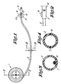
- an improved reel 1 according to the invention is represented onto which a hose 2 is wound which, at its free extremity, has a connection piece 3 with which a connection piece 4 of a working tool 5 can be connected in a suitable manner, generally by means of a bayonet coupling or such.
- connection piece 3 is provided with a switch, more particularly a push-button switch 6, which is connected to electrical conductors 7-8 which are provided through the hose 2, over the entire length, and which, at their other extremity, are connected, on one hand, to a connection terminal 9 of a driving motor 10 of the reel 1 according to the invention and, on the other hand, to the metal housing or earth of the reel 1.
- a switch more particularly a push-button switch 6, which is connected to electrical conductors 7-8 which are provided through the hose 2, over the entire length, and which, at their other extremity, are connected, on one hand, to a connection terminal 9 of a driving motor 10 of the reel 1 according to the invention and, on the other hand, to the metal housing or earth of the reel 1.
- the second connection terminal 11 of the motor 10 is connected further, by means of a conductor 12 with a slip ring 13 with which a brush 14 is cooperating which, by means of a conductor 15, is connected to a suitable power source, the second pole of which is connected to the earth of the reel 1, by means of a conductor 16.
- the slip ring 13 is suitably connected to the hub 17 of the reel 1, whereby a pulley 18 is fixed at this hub 17 which pulley cooperates with a pulley 19 at the exiting shaft of the motor 10, whereby these pulleys 18-19 are connected to each other by means of a belt 20.
- the reel 1 is provided freely rotatable on a pipe-shaped shaft 21 which also provides for the supply of compressed air to the hose 2, to which aim this pipe-shaft shaft 21 is fixedly attached in respect to the frame 22 of the reel 1 and, on one hand, and, on the other hand, is connected, by means of suitable connections 23 and 24 known in themselves, to the actual compressed-air supply pipe 25 and to conduit 26 which is in connection with the extremity of the hose 2 wound onto the reel 1.
- the reel 1 is suspended from a ceiling or such in a suitable manner.
- the application of the improved reel according to the present invention is very easy and as follows.
- the aforementioned push-button 6 shall only have to be pushed in order to give short pulses, whereby, for example, a short pulse during standstill starts the automatic winding of the hose; a short pulse during the automatic winding results in that the automatic winding is stopped, and a long pulse during standstill may result in that the winding speed is adjusted.
- the aforementioned electronic winding system will also be equipped with a power safety, in such a manner that, when the hose 2 during winding becomes stuck at something, the electronic winding system automatically stops the winding.
Landscapes
- Storing, Repeated Paying-Out, And Re-Storing Of Elongated Articles (AREA)
Claims (7)
- Verbesserte Schlauchhaspel des Typs, wobei eine bestimmte Schlauchmenge (2) auf eine eigentliche Haspel (1) gewickelt wird, die auf geeignete Weise mittels eines Elektromotors angetrieben werden kann und wobei dieser Schlauch an einem Ende mit einem Werkzeug (5) verbunden ist oder verbunden werden kann und an seinem anderen Ende auf geeeignete Weise mit einem Medium verbunden ist, und wobei durch den gesamten Schlauch (2) elektrische Leiter (7 und 8) verlaufen, die in der Nähe des freien Endes des Schlauchs mit einem Schalter (6) verbunden sind, beziehungsweise an ihrem anderen Ende mit dem vorgenannten Antriebsmotor (10) verbunden sind, um in der Lage zu sein, einen geeigneten Stromkreis durch letzteren zu schließen, dadurch gekennzeichnet, dass die elektrischen Leiter (7-8) in der Wanddicke des Schlauchs angebracht sind.
- Verbesserte Schlauchhaspel gemäß Anspruch 1, dadurch gekennzeichnet, dass die elektrischen Leiter (7 und 8) mit einer Anschlussklemme (9) des Antriebsmotors (10) beziehungsweise der metallischen Erde der Haspel (1) verbunden sind, wobei die zweite Anschlussklemme (11) des elektrischen Antriebsmotors (10) mit einem Schleifring (13) verbunden ist, der an der Nabe (17) der Schlauchhaspel befestigt ist, und wobei eine Bürste (14) mit diesem Schleifring (13) zusammenwirkt, die mit einem elektrischen Leiter (15) verbunden ist, der mit einer geeigneten Kraftquelle verbunden ist, während der zweite Leiter (16) dieser Kraftquelle mit der metallischen Erde der Schlauchhaspel verbunden ist.
- Verbesserte Schlauchhaspel gemäß Anspruch 1 oder 2, dadurch gekennzeichnet, dass ein elektronisches Schaltpaneel mit Mikroprozessor in dem Stromkreis vorgesehen ist.
- Verbesserte Schlauchhaspel gemäß Anspruch 1, dadurch gekennzeichnet, dass der vorgenannte Schalter (1) von einem Drucktaster gebildet wird.
- Verbesserte Schlauchhaspel gemäß Anspruch 1, dadurch gekennzeichnet, dass der Elektromotor (10) die Nabe (17) der Schlauchhaspel antreibt.
- Verbesserte Schlauchhaspel gemäß Anspruch 5, dadurch gekennzeichnet, dass eine Riemenscheibe (19) an der Welle des Elektromotors (10) angebracht ist, welche Riemenscheibe mittels eines Riemens (20) mit einer an der Nabe (17) der Schlauchhaspel befestigten Riemenscheibe (18) zusammenwirkt.
- Verbesserte Schlauchhaspel gemäß einem der vorgenannten Ansprüche, dadurch gekennzeichnet, dass die Haspel mit einem Pulsdetektionssystem versehen ist, das die Anzahl von Pulsen während des Abwickelns zählt und wobei während des Aufwickelns ebenfalls die Anzahl von Pulsen gezählt wird, derart, dass bei einer bestimmten Anzahl von Pulsen vor Null, die Geschwindigkeit des Motors elektronisch bis zu dem Moment, wenn die Anzahl von Pulsen wieder Null erreicht hat, reduziert wird.
Applications Claiming Priority (2)
| Application Number | Priority Date | Filing Date | Title |
|---|---|---|---|
| BE9800323A BE1011896A3 (nl) | 1998-04-29 | 1998-04-29 | Verbeterde slanghaspel. |
| BE9800323 | 1998-04-29 |
Publications (2)
| Publication Number | Publication Date |
|---|---|
| EP0953536A1 EP0953536A1 (de) | 1999-11-03 |
| EP0953536B1 true EP0953536B1 (de) | 2003-04-23 |
Family
ID=3891227
Family Applications (1)
| Application Number | Title | Priority Date | Filing Date |
|---|---|---|---|
| EP99201166A Expired - Lifetime EP0953536B1 (de) | 1998-04-29 | 1999-04-14 | Schlauchhaspel |
Country Status (8)
| Country | Link |
|---|---|
| US (1) | US6178992B1 (de) |
| EP (1) | EP0953536B1 (de) |
| BE (1) | BE1011896A3 (de) |
| CZ (1) | CZ147799A3 (de) |
| DE (1) | DE69907062T2 (de) |
| ES (1) | ES2209324T3 (de) |
| PL (1) | PL188014B1 (de) |
| TR (1) | TR199900914A1 (de) |
Cited By (1)
| Publication number | Priority date | Publication date | Assignee | Title |
|---|---|---|---|---|
| WO2004103875A1 (en) * | 2003-05-20 | 2004-12-02 | Robert Gerald Haskins | Electrically controlled hose reel rewind apparatus |
Families Citing this family (19)
| Publication number | Priority date | Publication date | Assignee | Title |
|---|---|---|---|---|
| US6991526B2 (en) * | 2002-09-16 | 2006-01-31 | Applied Materials, Inc. | Control of removal profile in electrochemically assisted CMP |
| US6543484B1 (en) * | 2000-08-15 | 2003-04-08 | Roderick Highsmith | Waste water disposal system |
| US7112121B2 (en) * | 2000-08-30 | 2006-09-26 | Micron Technology, Inc. | Methods and apparatus for electrical, mechanical and/or chemical removal of conductive material from a microelectronic substrate |
| BRPI0408250A (pt) | 2003-03-13 | 2006-03-01 | Great Stuff Inc | sistemas de controle de mangueira e de economia de energia, controladoras de válvula de economia de energia e métodos de funcionamento, de conservação de energia e de redução de energia consumida por uma controlodora de fluxo e por um sistema de controle |
| IL162797A (en) * | 2004-06-30 | 2008-08-07 | Avraham Levy | Device for reeling-in a hose |
| AU2005262296B2 (en) * | 2004-07-01 | 2011-06-02 | Great Stuff, Inc. | Systems and methods for controlling spooling of linear material |
| SE0602756L (sv) * | 2006-12-14 | 2008-06-15 | Canvac Ab | Anordning för att hämta eller distribuera ämnen |
| TW200848347A (en) | 2007-02-23 | 2008-12-16 | Great Stuff Inc | Remote control for valve and hose reel system |
| US8903577B2 (en) * | 2009-10-30 | 2014-12-02 | Lsi Industries, Inc. | Traction system for electrically powered vehicles |
| US8604709B2 (en) | 2007-07-31 | 2013-12-10 | Lsi Industries, Inc. | Methods and systems for controlling electrical power to DC loads |
| US7598683B1 (en) * | 2007-07-31 | 2009-10-06 | Lsi Industries, Inc. | Control of light intensity using pulses of a fixed duration and frequency |
| US9079746B2 (en) * | 2007-11-16 | 2015-07-14 | Kristen Omli | Pool lane line reel apparatuses, systems, and methods |
| BE1019479A3 (nl) * | 2010-09-08 | 2012-07-03 | Alpha Reel Bvba | Gemotoriseerde slanghaspel. |
| US8695912B2 (en) | 2011-04-19 | 2014-04-15 | Great Stuff, Inc. | Reel systems and methods for monitoring and controlling linear material slack |
| US9067759B2 (en) | 2012-04-17 | 2015-06-30 | Great Stuff, Inc. | Automatic reel devices and method of operating the same |
| US9067250B2 (en) * | 2012-12-20 | 2015-06-30 | Solar Turbines Incorporated | Portable tube coiler |
| JP6493813B2 (ja) * | 2014-04-04 | 2019-04-10 | 株式会社タツノ | 液化天然ガス充填装置 |
| CA2976834C (en) * | 2015-02-20 | 2023-09-26 | Deakin University | Firefighter training unit |
| CN112945116B (zh) * | 2021-01-25 | 2023-03-28 | 成都壹程科技有限公司 | 一种带温度自动补偿的光纤应变传感器 |
Family Cites Families (17)
| Publication number | Priority date | Publication date | Assignee | Title |
|---|---|---|---|---|
| US1659788A (en) * | 1927-03-31 | 1928-02-21 | Sifkovitz George | Hose reel |
| US2610810A (en) * | 1947-11-19 | 1952-09-16 | Farm Tools Inc | Reel mechanism |
| US2669483A (en) * | 1951-07-11 | 1954-02-16 | E C Fletcher | Device for transferring fluids |
| US2963227A (en) * | 1958-06-06 | 1960-12-06 | Symington Wayne Corp | Device for remotely winding a reel |
| FR1235380A (fr) * | 1959-05-23 | 1960-07-08 | Neu Sa | Aspirateur perfectionné à usage industriel, destiné en particulier au nettoyage de l'intérieur des véhicules |
| FR1284097A (fr) * | 1960-01-15 | 1962-02-09 | Atomic Energy Authority Uk | Dispositif de levage et d'enroulement de câbles, notamment pour la conduction d'électricité |
| SE414532B (sv) * | 1979-06-18 | 1980-08-04 | Blom H | Anordning vid en fjerrvermeledning samt sett att framstella en sadan anordning |
| US4487218A (en) * | 1982-06-25 | 1984-12-11 | Cascade Corporation | Line take-up assembly for a lift truck |
| US4730089A (en) * | 1983-09-02 | 1988-03-08 | Wyle Laboratories | Remotely controllable cable assembly |
| DE3921679A1 (de) * | 1989-07-03 | 1991-01-17 | Stemmann Technik Gmbh | Vorrichtung zur versorgung eines verfahrbaren, versorgungsnetzabhaengigen verbrauchers |
| IT1239357B (it) * | 1990-03-08 | 1993-10-20 | Migen Srl | Dispositivo per l'azionamento di elememti flessibili |
| US4993449A (en) * | 1990-06-21 | 1991-02-19 | Stutzman Larry L | Hose reel apparatus |
| US5289845A (en) * | 1992-11-12 | 1994-03-01 | Bowen Tools | Oilfield tubing reel and reel assembly |
| CA2093715A1 (en) * | 1993-04-08 | 1994-10-09 | Garry Workhoven | Vacuum hose storage and access apparatus for a central vacuum cleaning system |
| US5495995A (en) * | 1994-01-31 | 1996-03-05 | Reelcraft Industries, Inc. | Motor driven hose reel |
| US5709350A (en) * | 1996-02-14 | 1998-01-20 | Davis; Joseph Louis | Device for transferring fishing line |
| US5947148A (en) * | 1998-01-07 | 1999-09-07 | Devito; Robert | Fluid delivery hose recovery system |
-
1998
- 1998-04-29 BE BE9800323A patent/BE1011896A3/nl not_active IP Right Cessation
-
1999
- 1999-04-14 EP EP99201166A patent/EP0953536B1/de not_active Expired - Lifetime
- 1999-04-14 ES ES99201166T patent/ES2209324T3/es not_active Expired - Lifetime
- 1999-04-14 DE DE69907062T patent/DE69907062T2/de not_active Expired - Fee Related
- 1999-04-16 US US09/292,621 patent/US6178992B1/en not_active Expired - Fee Related
- 1999-04-26 PL PL33276999A patent/PL188014B1/pl not_active IP Right Cessation
- 1999-04-27 CZ CZ991477A patent/CZ147799A3/cs unknown
- 1999-04-27 TR TR1999/00914A patent/TR199900914A1/xx unknown
Cited By (1)
| Publication number | Priority date | Publication date | Assignee | Title |
|---|---|---|---|---|
| WO2004103875A1 (en) * | 2003-05-20 | 2004-12-02 | Robert Gerald Haskins | Electrically controlled hose reel rewind apparatus |
Also Published As
| Publication number | Publication date |
|---|---|
| DE69907062D1 (de) | 2003-05-28 |
| ES2209324T3 (es) | 2004-06-16 |
| DE69907062T2 (de) | 2003-12-11 |
| US6178992B1 (en) | 2001-01-30 |
| CZ147799A3 (cs) | 1999-11-17 |
| PL332769A1 (en) | 1999-11-08 |
| PL188014B1 (pl) | 2004-11-30 |
| TR199900914A1 (xx) | 1999-11-22 |
| EP0953536A1 (de) | 1999-11-03 |
| BE1011896A3 (nl) | 2000-02-01 |
Similar Documents
| Publication | Publication Date | Title |
|---|---|---|
| EP0953536B1 (de) | Schlauchhaspel | |
| US5762282A (en) | Remote retractable lifeline extender | |
| CN111675023B (zh) | 一种机电安装工程用电缆收放装置及其使用方法 | |
| EP0810153B1 (de) | Verfahren und vorrichtung zum umreifen von gegenständen | |
| KR100293322B1 (ko) | 물품의 매듭방법 및 매듭장치 | |
| US8485501B1 (en) | Wireless controlled apparatus for pulling wire through conduit | |
| US4012002A (en) | Automatic coupling mechanism for hose reels | |
| WO1999060295A2 (en) | Wire puller | |
| US6367732B1 (en) | Strapping machine with twisted belt drive | |
| US20110057157A1 (en) | Cable pulling machine | |
| US6003842A (en) | Installation for putting in electrical cable for indoor installations | |
| US20170189980A1 (en) | Soldering Wire Dispenser Apparatus | |
| US4822005A (en) | Cable pulling system and adaptor | |
| US6295740B1 (en) | Power-movement measuring tape | |
| EP1551086A1 (de) | Kabeltrommel | |
| EP2614025B1 (de) | Motorisierte schlauchwinde | |
| US3355148A (en) | Fish cable tool | |
| EP1953883A1 (de) | Vorrichtung mit Zugband | |
| KR102111413B1 (ko) | 폴리우레아 코팅 호스릴 제어 장치 | |
| KR200184453Y1 (ko) | 용접용 케이블 릴 | |
| KR101676801B1 (ko) | 장선 장치 | |
| USRE22113E (en) | Drain cleaner | |
| CN114688178A (zh) | 一种离合机构、卷线装置及地坪研磨机器人 | |
| KR102576857B1 (ko) | 유무선 모터 구동형 전선 권취장치 | |
| KR200344812Y1 (ko) | 농약 살포용 호스 권취기 |
Legal Events
| Date | Code | Title | Description |
|---|---|---|---|
| PUAI | Public reference made under article 153(3) epc to a published international application that has entered the european phase |
Free format text: ORIGINAL CODE: 0009012 |
|
| AK | Designated contracting states |
Kind code of ref document: A1 Designated state(s): DE ES FR GB IT NL PT SE |
|
| AX | Request for extension of the european patent |
Free format text: AL;LT;LV;MK;RO;SI |
|
| 17P | Request for examination filed |
Effective date: 20000427 |
|
| AKX | Designation fees paid |
Free format text: DE ES FR GB IT NL PT SE |
|
| 17Q | First examination report despatched |
Effective date: 20011129 |
|
| GRAH | Despatch of communication of intention to grant a patent |
Free format text: ORIGINAL CODE: EPIDOS IGRA |
|
| GRAH | Despatch of communication of intention to grant a patent |
Free format text: ORIGINAL CODE: EPIDOS IGRA |
|
| GRAA | (expected) grant |
Free format text: ORIGINAL CODE: 0009210 |
|
| AK | Designated contracting states |
Designated state(s): DE ES FR GB IT NL PT SE |
|
| PG25 | Lapsed in a contracting state [announced via postgrant information from national office to epo] |
Ref country code: NL Free format text: LAPSE BECAUSE OF FAILURE TO SUBMIT A TRANSLATION OF THE DESCRIPTION OR TO PAY THE FEE WITHIN THE PRESCRIBED TIME-LIMIT Effective date: 20030423 |
|
| REG | Reference to a national code |
Ref country code: GB Ref legal event code: FG4D |
|
| REF | Corresponds to: |
Ref document number: 69907062 Country of ref document: DE Date of ref document: 20030528 Kind code of ref document: P |
|
| PG25 | Lapsed in a contracting state [announced via postgrant information from national office to epo] |
Ref country code: SE Free format text: LAPSE BECAUSE OF FAILURE TO SUBMIT A TRANSLATION OF THE DESCRIPTION OR TO PAY THE FEE WITHIN THE PRESCRIBED TIME-LIMIT Effective date: 20030723 Ref country code: PT Free format text: LAPSE BECAUSE OF FAILURE TO SUBMIT A TRANSLATION OF THE DESCRIPTION OR TO PAY THE FEE WITHIN THE PRESCRIBED TIME-LIMIT Effective date: 20030723 |
|
| NLV1 | Nl: lapsed or annulled due to failure to fulfill the requirements of art. 29p and 29m of the patents act | ||
| ET | Fr: translation filed | ||
| PLBE | No opposition filed within time limit |
Free format text: ORIGINAL CODE: 0009261 |
|
| STAA | Information on the status of an ep patent application or granted ep patent |
Free format text: STATUS: NO OPPOSITION FILED WITHIN TIME LIMIT |
|
| 26N | No opposition filed |
Effective date: 20040126 |
|
| REG | Reference to a national code |
Ref country code: ES Ref legal event code: FG2A Ref document number: 2209324 Country of ref document: ES Kind code of ref document: T3 |
|
| PGFP | Annual fee paid to national office [announced via postgrant information from national office to epo] |
Ref country code: GB Payment date: 20050415 Year of fee payment: 7 |
|
| PGFP | Annual fee paid to national office [announced via postgrant information from national office to epo] |
Ref country code: FR Payment date: 20050418 Year of fee payment: 7 |
|
| PGFP | Annual fee paid to national office [announced via postgrant information from national office to epo] |
Ref country code: ES Payment date: 20050505 Year of fee payment: 7 |
|
| PGFP | Annual fee paid to national office [announced via postgrant information from national office to epo] |
Ref country code: DE Payment date: 20050622 Year of fee payment: 7 |
|
| PG25 | Lapsed in a contracting state [announced via postgrant information from national office to epo] |
Ref country code: GB Free format text: LAPSE BECAUSE OF NON-PAYMENT OF DUE FEES Effective date: 20060414 |
|
| PG25 | Lapsed in a contracting state [announced via postgrant information from national office to epo] |
Ref country code: ES Free format text: LAPSE BECAUSE OF NON-PAYMENT OF DUE FEES Effective date: 20060415 |
|
| PGFP | Annual fee paid to national office [announced via postgrant information from national office to epo] |
Ref country code: IT Payment date: 20060430 Year of fee payment: 8 |
|
| PG25 | Lapsed in a contracting state [announced via postgrant information from national office to epo] |
Ref country code: DE Free format text: LAPSE BECAUSE OF NON-PAYMENT OF DUE FEES Effective date: 20061101 |
|
| GBPC | Gb: european patent ceased through non-payment of renewal fee |
Effective date: 20060414 |
|
| REG | Reference to a national code |
Ref country code: FR Ref legal event code: ST Effective date: 20061230 |
|
| REG | Reference to a national code |
Ref country code: ES Ref legal event code: FD2A Effective date: 20060415 |
|
| PG25 | Lapsed in a contracting state [announced via postgrant information from national office to epo] |
Ref country code: FR Free format text: LAPSE BECAUSE OF NON-PAYMENT OF DUE FEES Effective date: 20060502 |
|
| PG25 | Lapsed in a contracting state [announced via postgrant information from national office to epo] |
Ref country code: IT Free format text: LAPSE BECAUSE OF NON-PAYMENT OF DUE FEES Effective date: 20070414 |