EP0952648B1 - Montant pour le chassis d'une armoire de distribution - Google Patents
Montant pour le chassis d'une armoire de distribution Download PDFInfo
- Publication number
- EP0952648B1 EP0952648B1 EP99104631A EP99104631A EP0952648B1 EP 0952648 B1 EP0952648 B1 EP 0952648B1 EP 99104631 A EP99104631 A EP 99104631A EP 99104631 A EP99104631 A EP 99104631A EP 0952648 B1 EP0952648 B1 EP 0952648B1
- Authority
- EP
- European Patent Office
- Prior art keywords
- profile
- fastening
- frame leg
- sides
- angle
- Prior art date
- Legal status (The legal status is an assumption and is not a legal conclusion. Google has not performed a legal analysis and makes no representation as to the accuracy of the status listed.)
- Expired - Lifetime
Links
Images


Classifications
-
- H—ELECTRICITY
- H02—GENERATION; CONVERSION OR DISTRIBUTION OF ELECTRIC POWER
- H02B—BOARDS, SUBSTATIONS OR SWITCHING ARRANGEMENTS FOR THE SUPPLY OR DISTRIBUTION OF ELECTRIC POWER
- H02B1/00—Frameworks, boards, panels, desks, casings; Details of substations or switching arrangements
- H02B1/01—Frameworks
- H02B1/013—Profiles for cabinet frames
Definitions
- the invention relates to a frame for a control cabinet.
- DE-U-29623065 and EP-A-0751595 disclose a frame leg for a frame of a control cabinet according to the prior art.
- the mounting portions and the profile sides of the profile inside represent different mounting levels in different directions, with the choice of the first and second angle their orientation relative to the outer sides of the frame can be determined. Moreover, can be optimized with the choice of these angles and the torsional rigidity of the frame leg and reduce the cost of materials.
- the mutually facing profile sides form an open towards the interior of the frame towards receiving mounting rails, which can expand the variation in the mounting options.
- the mounting options can be improved in that the fastening receptacles of the fastening portions have a first equal distance from the inner edges, and that the fastening receptacles of the profile sides have a second equal distance from the inner edges.
- first distances are selected equal to the second distances
- uniformly designed mounting rails, attachments and the like Can be attached to all attachment levels of the mounting portions and profile pages.
- the torsional stiffness of the frame leg can be increased by the fact that the profile sides are connected to each other and / or with the connecting portion.
- the installation in a frame can be simplified in that the frame leg is formed mirror-image to the associated compassiongestelldiagonalen.
- the first and second angles may be acute, right or obtuse, and so that the attachment planes may be laid in different directions.
- the profile pages are connected to each other directly or via a transition section.
- transition portion or the direct connection of the profile sides with the connecting portion of the profile outer part is still left a large margin for the choice of the angle between the outside of the frame and the mounting portions and the angle between the profile sides and the mounting portions.
- the transition section between the profile sides runs parallel to the facing part of the connecting portion and can be connected thereto.
- the fastening receptacles can be formed as bores and / or square or rectangular openings and extend in the profile longitudinal direction as rows with a uniform pitch.
- the fastening receptacles in the attachment sections and the profile pages in the training and / or the division of those in the profile pages may differ.
- the orientation of the fastening planes can be designed so that the fastening sections each extend parallel to the non-adjoining profile sides.
- the profile inner side is provided with a transition section between the profile sides, then it can be provided for expanding the fastening possibilities that the transition section is provided with fastening receptacles.
- the frame leg can be easily produced as a section of an extruded profile.
- the frame leg is formed as a punching and bending part, which is preferably merged in the region of the free edges of the profile pages, or that it is formed as a punching and bending part, in the region of the connecting portion is merged.
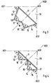
- FIGS. 1 to 8 shown as Querschitt embodiments of frame legs.
- the two orthogonal abutting outer sides of a frame indicated, the compassiongestelldiagonale RGD is shown as an angle bisector.
- the two outer sides AS1 and AS2 form a predominantlyeckkante AEK, which is not affected by the frame legs with the profile outside.
- the profile outside is referred to as a connecting portion 11, which starts from the two outer sides AS1 and AS2 and the outer corner AEK out a sufficiently large space FR for the articulation of a cabinet door and the sealing and introduction of the clashing here paneling elements, like side walls, back wall, closet door, allowed.
- the connecting portion 11 may also be designed differently, but always leave a free space FR to collaborateeckkante AEK.
- the fastening sections 12 and 14 are followed by profile sides 16 and 18, which are likewise provided with rows of fastening receptacles 17 and 19.
- the attachment portions 12 and 14 and the profile sides 16 and 18 form two inner edges IK1 and IK2.
- the fastening receptacles 13 and 15 of the fastening sections 12 and 14 have a first distance A1 from the inner edges IK1 and IK2, while the fastening receptacles 17 and 19 of the profile strips 16 and 18 have a second distance A2 from the inner edges IK1 and IK2.
- the distance A1 can also be selected equal to the distance A2.
- the profile sides 16 and 18 close with the subsequent attachment portion 12 and 14 an acute angle ⁇ .
- the fastening portions 12 and 14 facing away edges of the profile sides 16 and 18 are connected to each other via a transition portion 20.
- the transition section 20 may extend parallel to the facing part of the connecting section 11 of the profile outside and be firmly connected thereto.
- the transition section 20 can also extend at a distance parallel to the facing part of the connecting portion 11.
- the transition section 20 can consist of two overlapping end sections, which adjoin the profile sides 16 and 18.
- the shock and connection point can also be in the region of the connecting section 11 are located.
- the attachment receivers 13 and 15 of the attachment sections 12 and 14 may be of the same design and orientation as the attachment receptacles 17 and 19 of the profile sides 16 and 18. However, they may also differ in design, orientation and pitch.
- the angle ⁇ can be selected to be the same size as the angle ⁇ .
- the angles ⁇ and ⁇ differ significantly from the embodiment of FIG. 1, since the profile sides 16 and 18 collide directly and are centrally connected to the connecting portion 11.
- the frame legs of Fig. 2 is a mirror image of the compassiongestelldiagonalen RGD formed.
- the distances of the fastening receptacles 13 and 17 from the inner edge IK1 correspond to the distances between the fastening receptacles 15 and 19 from the inner edge IK2.
- the mounting portions 12 and 14 may be the same width as the profile sides 16 and 18 and half as wide as the connecting portion 11 are designed so that the two cavities of the frame leg form isosceles or equilateral triangles.
- the profile sides 16 and 18 may be directly connected to each other at a distance from the connecting portion 11.
- the angle ⁇ can be selected at an acute angle and the angle ⁇ at an obtuse angle.
- the distances A1 and A2 of the fastening receptacles from the inner edges IK1 and IK2 are different.
- the profile sides 16 and 18 can be connected to one another and / or to the connection section 11 directly or via a transition section 20.
- the profile outside may have a contact portion 21 which rests against the facing outside AS2 and assumes the transition from the connecting portion 11 of the profile outside to the mounting portion 14 of the profile inside.
- both ends of the connecting section 11 pass over contact sections 21 and 22 into the fastening sections 14 and 12 of the profile inner side.
- the profile sides 16 and 18 connect at an acute angle ⁇ to the mounting portions 12 and 14 and are directly connected to the connecting portion 11.
- the fastening receptacles 13, 15, 17 and 19 have the same distance from the associated inner edge IK1 or IK2.
- the profile sides 16 and 18 are connected to each other via a transition portion 20 which extends parallel to the connecting portion 11 at a distance, and may be provided with additional fastening receptacles 23.
- the widths of the attachment portions 12 and 14 and the profile sides 16 and 18 can also be chosen to be the same size and the contact webs 21 and 22 can be dimensioned so that the transition portion 20 or the Profile pages 16 and 18 can be connected directly to the connection section 11.
- Fig. 7 shows a frame leg, in which the angles ⁇ and ⁇ are obtuse.
- the contact sections 21 and 22 are adapted so that the interconnected profile sides 16 and 18 on the connecting portion 11 at least be supported or connected to this.
- the connecting portion 11 may be merged in the region of the support or connection point and overlap.
- the connecting portion 11 does not have to be rectilinear, it may also be formed step-like or from the contact sections 21 and 22, starting arbitrarily, if it leaves only enough free space FR to the outer corner AEK out.
- the mounting portions 12 and 14 are at an acute angle ⁇ to the outer sides AS1 and AS2 and the profile sides 16 and 18 close at an acute angle ⁇ to the mounting portions 12 and 14 at.
- the profile sides 16 and 18 are perpendicular to each other and parallel to their associated outer sides AS1 and AS2.
- the profile pages 16 and 18 meet in the frame frame diagonal RGD on the corner of the staircase-shaped connecting portion 11 and can be firmly connected thereto.
- the cross-section of the frame profile must not necessarily be designed mirror-symmetrically to the frame frame diagonal RGD both in the area of the profile outside and in the area of the profile inside. It is also unbalanced designs conceivable if special requirements are placed on the mounting options and mounting directions.
Landscapes
- Engineering & Computer Science (AREA)
- Power Engineering (AREA)
- Patch Boards (AREA)
- Assembled Shelves (AREA)
- Furniture Connections (AREA)
Claims (13)
- Montant pour le châssis d'une armoire de distribution, avec un côté extérieur de profilé comme partie d'assemblage (11) entre des côtés extérieurs (AS1, AS2) joints perpendiculairement l'un à l'autre du châssis, dans lequel des parties de fixation (12, 14) d'un côté intérieur de profilé sont raccordés à la partie d'assemblage (11), lesquelles sont pourvues de logements de fixation (13, 15) dans la direction longitudinale du profilé et se prolongent par des côtés de profilé (16, 18) également pourvus de logements de fixation (17, 19), dans lequel les parties de fixation (12, 14) forment un premier angle (α) avec les côtés extérieurs (AS1, AS2) du châssis et les côtés de profilé (16, 18) forment respectivement un deuxième angle (β) avec la partie de fixation adjacente (12 ou selon le cas 14), dans lequel les parties de fixation (12, 14) et les côtés de profilé (16, 18) forment deux arêtes intérieures (IK1, IK2) du côté intérieur de profilé, dans lequel les logements de fixation (13, 15) des parties de fixation (12, 14) présentent une même première distance (A1) par rapport aux arêtes intérieures (IK1, IK2), dans lequel les logements de fixation (17, 19) des côtés de profilé (16, 18) présentent une même deuxième distance (A2) par rapport aux arêtes intérieures (IK1, IK2), caractérisé en ce que les premières distances (A1) sont choisies égales aux deuxièmes distances (A2) et en ce que les côtés de profilé (16, 18) touchent directement la partie d'assemblage (11) et sont assemblés à celle-ci.
- Montant pour le châssis d'une armoire de distribution, avec un côté extérieur de profilé comme partie d'assemblage (11) entre des côtés extérieurs (AS1, AS2) joints perpendiculairement l'un à l'autre du châssis, dans lequel des parties de fixation (12, 14) d'un côté intérieur de profilé sont raccordés à la partie d'assemblage (11), lesquelles sont pourvues de logements de fixation (13, 15) dans la direction longitudinale du profilé et se prolongent par des côtés de profilé (16, 18) également pourvus de logements de fixation (17, 19), dans lequel les parties de fixation (12, 14) forment un premier angle (α) avec les côtés extérieurs (AS1, AS2) du châssis et les côtés de profilé (16, 18) forment respectivement un deuxième angle (β) avec la partie de fixation adjacente (12 ou selon le cas 14), dans lequel les parties de fixation (12, 14) et les côtés de profilé (16, 18) forment deux arêtes intérieures (IK1, IK2) du côté intérieur de profilé, dans lequel les logements de fixation (13, 15) des parties de fixation (12, 14) présentent une même première distance (A1) par rapport aux arêtes intérieures (IK1, IK2), dans lequel les logements de fixation (17, 19) des côtés de profilé (16, 18) présentent une même deuxième distance (A2) par rapport aux arêtes intérieures (IK1, IK2), caractérisé en ce que les premières distances (A1) sont choisies égales aux deuxièmes distances (A2), en ce que les côtés de profilé (16, 18) sont reliés l'un à l'autre par une partie de jonction (20) et en ce que la partie de jonction (20) est parallèle à distance à la partie d'assemblage (11).
- Montant selon l'une quelconque des revendications 1 ou 2, caractérisé en ce qu'il présente une forme symétrique par réflexion par rapport à la diagonale associée du châssis (RGD).
- Montant selon l'une quelconque des revendications 1 à 3, caractérisé en ce que les premiers angles (α) ont été choisis aigus, droits ou obtus.
- Montant selon l'une quelconque des revendications 1 à 4, caractérisé en ce que les deuxièmes angles (β) ont été choisis aigus, droits ou obtus.
- Montant selon l'une quelconque des revendications 1 à 5, caractérisé en ce que les logements de fixation (13, 15, 17, 19) des parties de fixation (12, 14) et des côtés de profilé (16, 18) sont des trous forés et/ou des passages carrés ou rectangulaires.
- Montant selon l'une quelconque des revendications 1 à 6, caractérisé en ce que les logements de fixation (13, 15, 17, 19) sont pratiqués dans les parties de fixation (12, 14) et les côtés de profilé (16, 18) en ligne avec un pas unitaire dans la direction longitudinale du profilé.
- Montant selon l'une quelconque des revendications 1 à 7, caractérisé en ce que les logements de fixation (13, 15) des parties de fixation (12, 14) se distinguent par leur forme et/ou leur pas des logements de fixation (17, 19) des côtés de profilé (16, 18).
- Montant selon l'une quelconque des revendications 1 à 8, caractérisé en ce que les parties de fixation (12, 14) sont chaque fois parallèles aux côtés de profilé non adjacents (18 ou selon le cas 16).
- Montant selon l'une quelconque des revendications 1 à 9, caractérisé en ce que la partie de jonction (20) est pourvue de logements de fixation (23).
- Montant selon l'une quelconque des revendications 1 à 10, caractérisé en ce qu'il est constitué par une section d'un profilé extrudé.
- Montant selon l'une quelconque des revendications 1 à 11, caractérisé en ce qu'il est formé par une pièce découpée et pliée, qui est jointe de préférence dans la région des arêtes libres des côtés de profilé (16, 18).
- Montant selon l'une quelconque des revendications 1 à 12, caractérisé en ce qu'il est formé par une pièce découpée et pliée, qui est jointe dans la région de la partie d'assemblage (11).
Applications Claiming Priority (2)
| Application Number | Priority Date | Filing Date | Title |
|---|---|---|---|
| DE19818603A DE19818603A1 (de) | 1998-04-20 | 1998-04-20 | Rahmenschenkel für ein Rahmengestell eines Schaltschrankes |
| DE19818603 | 1998-04-20 |
Publications (2)
| Publication Number | Publication Date |
|---|---|
| EP0952648A1 EP0952648A1 (fr) | 1999-10-27 |
| EP0952648B1 true EP0952648B1 (fr) | 2007-05-23 |
Family
ID=7865822
Family Applications (1)
| Application Number | Title | Priority Date | Filing Date |
|---|---|---|---|
| EP99104631A Expired - Lifetime EP0952648B1 (fr) | 1998-04-20 | 1999-03-09 | Montant pour le chassis d'une armoire de distribution |
Country Status (4)
| Country | Link |
|---|---|
| US (1) | US6206211B1 (fr) |
| EP (1) | EP0952648B1 (fr) |
| JP (1) | JPH11341616A (fr) |
| DE (1) | DE19818603A1 (fr) |
Families Citing this family (7)
| Publication number | Priority date | Publication date | Assignee | Title |
|---|---|---|---|---|
| US6902077B1 (en) * | 1998-11-09 | 2005-06-07 | The Procter & Gamble Company | Container |
| US20010050516A1 (en) * | 2000-03-09 | 2001-12-13 | Nitto Electric Works, Ltd | Frame construction of a cabinet or cabinets for containing electronic and electric equipments |
| US6965075B2 (en) * | 2001-03-01 | 2005-11-15 | Nitto Electric Works, Ltd. | Frame for electrical and electronic equipment housing cabinets and a frame joining structure |
| DE10136681C2 (de) * | 2001-07-27 | 2003-10-02 | Eldon Holding Ab Rijswijk | Rahmengestell |
| WO2013121434A1 (fr) | 2012-02-16 | 2013-08-22 | Bartakke Ajit Vasudeo | Coffret électrique modulaire de composants bidimensionnels boulonnés pour montage interne très flexible |
| DE102014100417B3 (de) * | 2014-01-15 | 2015-04-02 | Rittal Gmbh & Co. Kg | Rahmenprofil für ein Rahmengestell eines Schaltschranks sowie Befestigungsclip für das Rahmenprofil |
| DE102014101401A1 (de) * | 2014-02-05 | 2015-08-06 | Rittal Gmbh & Co. Kg | Anreih-Schaltschranksystem |
Family Cites Families (13)
| Publication number | Priority date | Publication date | Assignee | Title |
|---|---|---|---|---|
| DE8335383U1 (de) * | 1983-12-09 | 1984-04-05 | Rittal-Werk Rudolf Loh Gmbh & Co Kg, 6348 Herborn | Rahmengestell für einen Schaltschrank |
| FR2648005B1 (fr) * | 1989-06-05 | 1993-11-26 | Merlin Gerin | Armoire etanche d'appareillage electrique |
| DE4336204C2 (de) * | 1993-10-23 | 1996-11-07 | Loh Kg Rittal Werk | Rahmengestell für einen Schaltschrank |
| DE4336285A1 (de) * | 1993-10-25 | 1995-04-27 | Loh Kg Rittal Werk | Rahmengestell für einen Schaltschrank |
| DE4340934C2 (de) * | 1993-12-01 | 1996-10-17 | Loh Kg Rittal Werk | Verfahren zum Aufbau eines Schaltschrankes und zum Einbau von Einbauten |
| DE4439551C1 (de) * | 1994-11-05 | 1995-12-21 | Loh Kg Rittal Werk | Rahmenschenkel für ein Rahmengestell eines Schaltschrankes |
| DE4439607C1 (de) * | 1994-11-05 | 1995-12-14 | Loh Kg Rittal Werk | Schaltschrank mit einem Rahmengestell |
| DE4439614C1 (de) * | 1994-11-05 | 1995-12-14 | Loh Kg Rittal Werk | Rahmengestell für einen Schaltschrank |
| DE4446223C1 (de) * | 1994-12-23 | 1996-04-04 | Loh Kg Rittal Werk | Schaltschrank mit einem Rahmengestell |
| DE19536950C1 (de) * | 1995-10-04 | 1996-11-21 | Loh Kg Rittal Werk | Rahmenschenkel für ein Rahmengestell eines Schaltschrankes |
| DE19536926C2 (de) * | 1995-10-04 | 1999-02-04 | Loh Kg Rittal Werk | Rahmenschenkel für einen Schaltschrank |
| DE29623065U1 (de) * | 1996-11-19 | 1997-10-02 | Rittal-Werk Rudolf Loh GmbH & Co. KG, 35745 Herborn | Rahmenprofil für ein Rahmengestell eines Schaltschrankes |
| DE19712362C1 (de) * | 1997-03-25 | 1998-07-30 | Loh Kg Rittal Werk | Vorrichtung zum Befestigen einer Tragschiene an Rahmenschenkeln und Montageplatten eines Schaltschrankes |
-
1998
- 1998-04-20 DE DE19818603A patent/DE19818603A1/de not_active Ceased
-
1999
- 1999-03-09 EP EP99104631A patent/EP0952648B1/fr not_active Expired - Lifetime
- 1999-04-19 US US09/294,767 patent/US6206211B1/en not_active Expired - Fee Related
- 1999-04-19 JP JP11111179A patent/JPH11341616A/ja active Pending
Also Published As
| Publication number | Publication date |
|---|---|
| DE19818603A1 (de) | 1999-10-21 |
| US6206211B1 (en) | 2001-03-27 |
| JPH11341616A (ja) | 1999-12-10 |
| EP0952648A1 (fr) | 1999-10-27 |
Similar Documents
| Publication | Publication Date | Title |
|---|---|---|
| EP0853832B1 (fr) | Cadre pour armoire de distribution | |
| DE3731547C2 (fr) | ||
| EP0789983B1 (fr) | Montants pour baies d'armoires de distribution | |
| EP0951116B1 (fr) | Montant pour le chassis d'une armoire de distribution | |
| WO1998023006A1 (fr) | Jeu de pieces pour baie a element d'assemblage d'angle pour montants profiles verticaux | |
| DE4132803C3 (de) | Hohlprofil für ein Rahmengestell eines Schaltschrankes | |
| EP0939986B1 (fr) | Armoire de distribution comportant une baie | |
| EP0939988A1 (fr) | Element d'assemblage d'angle pour baie | |
| DE29623559U1 (de) | Rahmengestell mit mehreren Montageebenen | |
| EP0951115B1 (fr) | Montant pour un chassis d'une armoire de distribution | |
| DE60015336T2 (de) | Rahmenstruktur für ein gehäuse für elektrische anlage | |
| EP0945941A1 (fr) | Cadre pour armoire de distribution | |
| EP0939980B1 (fr) | Baie comportant un cadre inferieur et un cadre superieur constitues d'un profile continu | |
| EP0952648B1 (fr) | Montant pour le chassis d'une armoire de distribution | |
| EP1604437B1 (fr) | Bati con u pour une armoire de distribution | |
| DE102007059204A1 (de) | Schaltschrank oder Rack | |
| EP0757852A1 (fr) | Armoire de distribution munie d'une baie et d'elements de porte | |
| DE19544432C2 (de) | Rahmengestell für einen Schaltschrank | |
| DE29823389U1 (de) | Rahmenschenkel für ein Rahmengestell eines Schaltschrankes | |
| DE29823390U1 (de) | Rahmenschenkel für ein Rahmengestell eines Schaltschrankes | |
| EP1653579B1 (fr) | Rail profilé pour construire un chassis, en particulier pour une armoire électrique | |
| DE10311374B4 (de) | Bausatz zum Erstellen von Rahmenaufbauten für Schaltschränke | |
| DE29823391U1 (de) | Rahmenschenkel für ein Rahmengestell eines Schaltschrankes | |
| DE29820610U1 (de) | Rahmengestell für einen Schaltschrank | |
| DE2232011A1 (de) | Leitungsfuehrung fuer starkstrom- und fernmeldekabel |
Legal Events
| Date | Code | Title | Description |
|---|---|---|---|
| PUAI | Public reference made under article 153(3) epc to a published international application that has entered the european phase |
Free format text: ORIGINAL CODE: 0009012 |
|
| AK | Designated contracting states |
Kind code of ref document: A1 Designated state(s): FR GB IT |
|
| AX | Request for extension of the european patent |
Free format text: AL;LT;LV;MK;RO;SI |
|
| 17P | Request for examination filed |
Effective date: 20000427 |
|
| AKX | Designation fees paid |
Free format text: FR GB IT |
|
| REG | Reference to a national code |
Ref country code: DE Ref legal event code: 8566 |
|
| GRAP | Despatch of communication of intention to grant a patent |
Free format text: ORIGINAL CODE: EPIDOSNIGR1 |
|
| GRAS | Grant fee paid |
Free format text: ORIGINAL CODE: EPIDOSNIGR3 |
|
| GRAA | (expected) grant |
Free format text: ORIGINAL CODE: 0009210 |
|
| AK | Designated contracting states |
Kind code of ref document: B1 Designated state(s): FR GB IT |
|
| REG | Reference to a national code |
Ref country code: GB Ref legal event code: FG4D Free format text: NOT ENGLISH |
|
| GBT | Gb: translation of ep patent filed (gb section 77(6)(a)/1977) |
Effective date: 20070702 |
|
| ET | Fr: translation filed | ||
| PLBE | No opposition filed within time limit |
Free format text: ORIGINAL CODE: 0009261 |
|
| STAA | Information on the status of an ep patent application or granted ep patent |
Free format text: STATUS: NO OPPOSITION FILED WITHIN TIME LIMIT |
|
| 26N | No opposition filed |
Effective date: 20080226 |
|
| REG | Reference to a national code |
Ref country code: FR Ref legal event code: PLFP Year of fee payment: 17 |
|
| PGFP | Annual fee paid to national office [announced via postgrant information from national office to epo] |
Ref country code: IT Payment date: 20150326 Year of fee payment: 17 |
|
| PGFP | Annual fee paid to national office [announced via postgrant information from national office to epo] |
Ref country code: FR Payment date: 20150319 Year of fee payment: 17 Ref country code: GB Payment date: 20150324 Year of fee payment: 17 |
|
| GBPC | Gb: european patent ceased through non-payment of renewal fee |
Effective date: 20160309 |
|
| REG | Reference to a national code |
Ref country code: FR Ref legal event code: ST Effective date: 20161130 |
|
| PG25 | Lapsed in a contracting state [announced via postgrant information from national office to epo] |
Ref country code: FR Free format text: LAPSE BECAUSE OF NON-PAYMENT OF DUE FEES Effective date: 20160331 Ref country code: GB Free format text: LAPSE BECAUSE OF NON-PAYMENT OF DUE FEES Effective date: 20160309 |
|
| PG25 | Lapsed in a contracting state [announced via postgrant information from national office to epo] |
Ref country code: IT Free format text: LAPSE BECAUSE OF NON-PAYMENT OF DUE FEES Effective date: 20160309 |