EP0952405A2 - Underfloor heating - Google Patents
Underfloor heating Download PDFInfo
- Publication number
- EP0952405A2 EP0952405A2 EP99106731A EP99106731A EP0952405A2 EP 0952405 A2 EP0952405 A2 EP 0952405A2 EP 99106731 A EP99106731 A EP 99106731A EP 99106731 A EP99106731 A EP 99106731A EP 0952405 A2 EP0952405 A2 EP 0952405A2
- Authority
- EP
- European Patent Office
- Prior art keywords
- underfloor heating
- heating
- heating according
- underfloor
- radiators
- Prior art date
- Legal status (The legal status is an assumption and is not a legal conclusion. Google has not performed a legal analysis and makes no representation as to the accuracy of the status listed.)
- Withdrawn
Links
Images


Classifications
-
- F—MECHANICAL ENGINEERING; LIGHTING; HEATING; WEAPONS; BLASTING
- F24—HEATING; RANGES; VENTILATING
- F24D—DOMESTIC- OR SPACE-HEATING SYSTEMS, e.g. CENTRAL HEATING SYSTEMS; DOMESTIC HOT-WATER SUPPLY SYSTEMS; ELEMENTS OR COMPONENTS THEREFOR
- F24D5/00—Hot-air central heating systems; Exhaust gas central heating systems
- F24D5/06—Hot-air central heating systems; Exhaust gas central heating systems operating without discharge of hot air into the space or area to be heated
- F24D5/10—Hot-air central heating systems; Exhaust gas central heating systems operating without discharge of hot air into the space or area to be heated with hot air led through heat-exchange ducts in the walls, floor or ceiling
-
- F—MECHANICAL ENGINEERING; LIGHTING; HEATING; WEAPONS; BLASTING
- F24—HEATING; RANGES; VENTILATING
- F24D—DOMESTIC- OR SPACE-HEATING SYSTEMS, e.g. CENTRAL HEATING SYSTEMS; DOMESTIC HOT-WATER SUPPLY SYSTEMS; ELEMENTS OR COMPONENTS THEREFOR
- F24D13/00—Electric heating systems
- F24D13/02—Electric heating systems solely using resistance heating, e.g. underfloor heating
- F24D13/022—Electric heating systems solely using resistance heating, e.g. underfloor heating resistances incorporated in construction elements
-
- F—MECHANICAL ENGINEERING; LIGHTING; HEATING; WEAPONS; BLASTING
- F24—HEATING; RANGES; VENTILATING
- F24D—DOMESTIC- OR SPACE-HEATING SYSTEMS, e.g. CENTRAL HEATING SYSTEMS; DOMESTIC HOT-WATER SUPPLY SYSTEMS; ELEMENTS OR COMPONENTS THEREFOR
- F24D3/00—Hot-water central heating systems
- F24D3/12—Tube and panel arrangements for ceiling, wall, or underfloor heating
- F24D3/14—Tube and panel arrangements for ceiling, wall, or underfloor heating incorporated in a ceiling, wall or floor
- F24D3/141—Tube mountings specially adapted therefor
- F24D3/142—Tube mountings specially adapted therefor integrated in prefab construction elements
-
- Y—GENERAL TAGGING OF NEW TECHNOLOGICAL DEVELOPMENTS; GENERAL TAGGING OF CROSS-SECTIONAL TECHNOLOGIES SPANNING OVER SEVERAL SECTIONS OF THE IPC; TECHNICAL SUBJECTS COVERED BY FORMER USPC CROSS-REFERENCE ART COLLECTIONS [XRACs] AND DIGESTS
- Y02—TECHNOLOGIES OR APPLICATIONS FOR MITIGATION OR ADAPTATION AGAINST CLIMATE CHANGE
- Y02B—CLIMATE CHANGE MITIGATION TECHNOLOGIES RELATED TO BUILDINGS, e.g. HOUSING, HOUSE APPLIANCES OR RELATED END-USER APPLICATIONS
- Y02B30/00—Energy efficient heating, ventilation or air conditioning [HVAC]
Definitions
- the invention relates to underfloor heating according to the preamble of patent claim 1.
- the subject matter of the invention is a portable or retrofittable underfloor heating, in particular in a modular design, which can subsequently be installed by simply placing it on the existing floor area and, if necessary, also being taken up again and reinstalled at another location.
- U1 discloses a heated floor, in particular for animal stalls, in which an electrical power supply is also to be dispensed with. Rather, the heated floor is to be connected to an existing hot water circuit of a central building heating system via self-closing couplings. However, if there are leaks in the heating floor and / or in the couplings, this leads to a pressure drop in the building heating system and possibly to the ingress of air, so that the building heating system has to be vented and the water loss has to be replenished.
- DE 297 03 432 U1 discloses a portable heating mat for use outdoors, for example for market stalls, which can either be provided with heating wires for connection to the power supply system or with cavities for the passage of a liquid heating medium.
- a flow heater with a circulation pump is provided for the latter case.
- This instantaneous water heater is heated by the combustion of vaporized liquid gases or other liquid fuels such as mineral oil, RME or alcohol.
- the invention has for its object to provide an easy to design and re-usable underfloor heating of the type described above, which can be connected to a power supply, can be operated independently, i.e., does not require a connection to a building's hot water circuit, no combustion gases and in particular none at room temperature condensable gases or vapors are generated and the available air humidity is not increased but reduced.
- the underfloor heating according to the invention can be easily and subsequently installed easily, with hardly any room height being lost. With a corresponding distance from doors that open inwards, they do not need to be shortened at the bottom, shortened or raised at the top. This means that all types of floors, including those in old buildings, can be retrofitted with underfloor heating. This leads to a pleasant atmosphere, particularly in bathrooms that are not heatable or only weakly heatable, because the cold and tiled floor surfaces are shielded or covered from the person in the room, which is extremely pleasant especially when stepping on bare feet.
- the invention does not require a connection to a building-side hot water circuit, can be operated autonomously, does not generate any combustion gases and in particular does not produce any gases or vapors that are condensable at room temperature and does not increase the existing atmospheric humidity, but rather lowers the relative atmospheric humidity by increasing the temperature, so that none in closed rooms extremely undesirable a humid or even humid atmosphere arises that would create an uneasiness.
- a floor heating 1 which consists of several plate-shaped radiators 3 placed on an existing floor surface 2, which abut each other at joints 5.
- An outer electrical Connection 4 is indicated by a cable harness that leads to an electrically heated instantaneous water heater 6 for heating a heating medium.
- Said heating medium can be both hot water (or another, frost-proof liquid) and warm air, water being controlled in a circuit in a temperature-controlled manner, while warm air can either be wholly or partly circulated or completely or partially released into the room air, which has several additional advantages: With air heating, there are no sealing problems with multi-unit underfloor heating, for example in the case of a modular design, yes, it is even possible to specifically deliver warm air to the room.
- the fluid heating medium is passed on through internal channels and - in the case of liquids - through plug connections or couplings, not shown here, which are likewise concealed in the separating joints 5 and which also bridge the separating joints 5.
- the heating can be carried out in a closed circuit, in addition to a fluid medium such as air or water, using oil or other liquid hydrocarbons as heat carriers, the liquid hydrocarbon likewise being heated in the electrically heated instantaneous water heater 6. Temperatures between about 30 and 50 degrees are sufficient.
- the connections are concealed in a distributor plate 3a, which also functions as a Radiator has, below the heat exchanger 6.
- the circuit can also be closed by an external line 15, which does not even have to be thermally insulated, because it contributes to space heating. This line 15, indicated by dashed lines, then leads from the other end of the underfloor heating 1 back to the instantaneous water heater 6.
- the radiators 3 have a square plan with an edge length of approximately 50 cm and are arranged in a grid dimension. It can be seen that the number and distribution of the radiators can be chosen and designed as desired.
- the individual radiators 3 are rigid to prevent mutual movement and local lifting from the floor surface 2. However, they can also be designed flexibly in the manner of mats if it is ensured that they cannot bend and / or shift when entering. For the same purpose, and in order to prevent displacement on the floor surface, the individual radiators 3 are positively connected to one another, for example by dovetail connections or by the undercut tongue and groove connections 7 shown.
- the outer sides 3b of the radiators 3, which are not connected to an adjacent radiator 3 are connected to wedge-shaped transition pieces 8, the wedge-shaped edges 8a of which lie in the same plane as the lower sides 3c of all the other radiators 3 and 3a. But it can also be used on the outer circumference - not shown - special radiators to which analog "ramps" are molded.
- the undersides 3c of the radiators 3, for example at the corners and possibly additionally in the middle, are provided with at least one heat-insulating spacer.
- the air located between the radiators 3 and the bottom surface 2 acts as a heat insulator.
- the heat-insulating spacers can be designed as - preferably profiled - heat-insulating panels 9, which are shown in FIG. 2 and whose outline corresponds to that Outline of the radiator 3 corresponds.
- the thermal insulation boards 9 preferably have anti-sliding properties.
- the tops of the radiators 3 and 3a are provided with a decorative covering 11, which is preferably non-slip.
- a "noble covering" can consist of thin marble or artificial stone slabs.
- the radiators are arranged in front of, below and to the side of the wash basin 10.
- sealing material 12 is arranged in the joints 5 between the radiators 3 and 3a.
- This can, for example, be continuously injected in the form of silicone resin into grooves which are arranged in the parting lines 5, as shown in FIG. 2.
- sealing profiles 13 are inserted into the parting lines 5 between the radiators 3 and 3a.
- a very effective seal can also be achieved in that, alternatively or in addition, the decorative coverings 11 of a plurality of radiators 3 and 3a are arranged so as to overlap the separating joints 5, which is not particularly shown.
- a particularly simple and inexpensive production can consist in that the radiators 3 and 3a are provided with grooves 14 which are open on one side, which is also indicated in FIG. 2 by the dashed lines. Grooves 14 which are open at the top are closed by the correspondingly stiff decorative covering 11. Grooves open at the bottom are closed by the thermal insulation plate 9. Pipes that are continuously laid over all radiators can also be inserted into the grooves (which is not shown), which means the otherwise necessary connection points can be omitted between the individual radiators 3 and 3a. If, on the other hand, you want to take up the radiators again when moving, it is advisable to arrange separation points or couplings between the individual radiators.
- the supporting part of the radiators 3 and 3a can be made of metal, e.g. an aluminum alloy, one pressed in a mold or made of an extruded plastic and / or another press material, such as chipboard, mineral plate or textile fiber material bound with a preferably water-resistant binder, and even non-usable but stable waste materials, which thereby lead to become recyclables.
- the load-bearing parts of the radiators 3 and 3a can consist of extruded profiles or of pressed bodies provided with grooves 14 that are open on one side. It is also possible to subsequently produce the elements of the form-fitting connections 7 by machining processes, such as by milling.
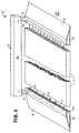
- FIG. 3 shows a radiator 3 with an entire register of continuous flow channels, through which warm air is passed, for example.
- Such plate-shaped parts are commercially available, for example, as so-called extruded "web glass” for small roofs and with considerable lengths.
- Wedge-shaped end pieces 16 and 17 are also extruded profiles and radiators, the ends of which are closed by wedge-shaped walls 18 and 19. Openings 21 are incorporated into the vertical side walls 20, through which warm air is introduced into the radiator 3 in the direction of the arrows. At its other end, slightly cooled air exits in the direction of the arrows and into the other end piece 17.
- the end piece 16 is therefore a distribution channel
- the end piece 17 is a collecting channel.
- the warm air is circulated through pipe heater 22 via pipe sockets 22 and 23, in which a heating resistor and a blower (both not shown) are arranged in series.
- a heating resistor and a blower both not shown
- the outlet temperature is preferably regulated to about 40 degrees so that the heating element 3 can also be entered with bare feet (e.g. in the bathroom).
- a correspondingly low heating output is sufficient, since the air - in contrast to a hair dryer - is circulated and only the heat losses have to be compensated. Nevertheless, a cozy atmosphere arises above the arrangement, which displaces the influence of the cold floor surface 2.
- the pipe sockets 22 and 23 are preferably largely telescopically guided in the housing 6a of the instantaneous water heater 6, so that the heat exchanger 6 can be lowered onto the end pieces 16 and 17 and onto the heating element 3 and forms a unit with this - visually appealing.
- the arrangement can be easily disassembled and picked up and put together again in another place without tools. Structural elements of the subject matter of FIGS. 1 and 2 can be adopted without further ado.
- FIG. 4 shows - to explain the various possible uses and combinations - a perspective view of an underfloor heating system consisting of several - in some cases different radiators 27, 28, 29 and 30.
- the centerpiece is a continuous closed hollow body 24 to which all radiators of equal length and rectangular, aligned parallel to each other, are connected.
- a continuous-flow heater 6 is arranged above the hollow body, which can optionally be designed for the generation of hot air and / or heating liquid and which is connected to the two ends of the hollow body 24 via lines 6b and 6c.
- the continuous-flow heater 6 has guide devices (not shown) in its interior for the air flow required in each case.
- similar radiators will be connected to the hollow body 24 within a floor heating system 1. However, it is possible to create different "climatic zones" above floor heating by varying the radiators.
- the instantaneous water heater 6 and the hollow body 24 can also be designed as an integral component and have, for example, in a common housing, which is not shown in particular.
- the heating element 27 is an air heating element analogous to FIG. 3, but open at one end for additional room heating, so that the openings 27a of the air ducts running through in the longitudinal direction can be seen.
- the heater 28 is also an air heater, but is closed at its free ends by a wall 28a.
- the warm air is returned in a U-shape to the hollow body 24 and heated again therein.
- the heating element 29 is a liquid heating element, into which soft copper tubes 14b are pressed, as described above with reference to FIG. 2. The connection is then made by liquid-tight couplings 25.
- the heating element 30 is provided with a large number of the finest nozzles or air outlet openings 31 directed upwards, which generate a thermal effect supported by the nozzle currents above the heating element 30 and thus a hot air column with a low flow velocity, which creates its own and very pleasant microclimate in the room.
- the end is through a wall 30a is closed, but - preferably adjustable - air openings in this wall can be used to adjust the thermals, that is to say to change the air distribution.
- two drainage openings 30b are provided. Due to the low relative humidity of the warm air, drying takes place very quickly in any case.
- the radiator 30 is in any case the quickest and within a few seconds to bring the operating temperature of both the upper side or standing surface and the emerging warm air and to produce it extremely inexpensively.
- a perforated panel radiator can also be used as a dry air source for a laundry drying rack placed above it, which has particular advantages not only in the cold and humid season.
- the hollow body 24 is designed as a rigid and closed at the ends box profile with inner flow channels.
- the radiators 27 to 30 are positively connected to the hollow body 24. This eliminates connections within the other joints 5 between the long sides of the radiators. A particularly effective securing of the position can be achieved by adhesive coverings, preferably by those that allow a resumption.
- the top of the hollow body 24 is provided over a part of its length with a plurality of outlet openings 26 for warm air, via which a towel holder 32 can be attached with particular advantage.
- the warm air is used to preheat the towels quickly and as dry air for wet towels or other items of laundry, which has special advantages not only in the cold and humid season.
- FIG. 5 shows a variant of the object according to FIG. 3.
- a heating element 3 is arranged, which can also be replaced by one or more of the heating elements 27 to 30 according to FIG. 4 and is therefore only exemplary.
- the radiator 3 forms a structural unit with the instantaneous water heater 6, which is fixed, but detachable, placed on the radiator 3 and whose electrical connection has been omitted for the sake of simplicity.
- heating is possible using warm air or a circulating liquid. Dirt spaces that are difficult to access are avoided in this way.
- FIG. 6 shows a possibility of combining the underfloor heating 1 according to FIG. 5 with a wash basin 35, in front of which the radiator 3 is arranged as a standing surface.
- the instantaneous water heater 6 is accommodated in the wash basin 35 and connected to the heating element 3 via hidden lines 6b and 6c.
- the end pieces 33 and 34 can have aligned extensions 33a and 34a shown in dashed lines on both sides of the washstand 35 in order to avoid "dead corners" which are difficult to clean.
- the top of the instantaneous water heater can then even serve as a towel rack, so that preheated towels are always available.
- the subject of the invention also has particular advantages in apartment buildings in which the central heating is operated at night with a temperature reduction. Early risers then suffer from an unpleasant bathroom temperature, the comfort values of which are only gradually achieved even after switching up to a daytime temperature.
Landscapes
- Engineering & Computer Science (AREA)
- Physics & Mathematics (AREA)
- Thermal Sciences (AREA)
- Chemical & Material Sciences (AREA)
- Combustion & Propulsion (AREA)
- Mechanical Engineering (AREA)
- General Engineering & Computer Science (AREA)
- Central Heating Systems (AREA)
- Steam Or Hot-Water Central Heating Systems (AREA)
- Floor Finish (AREA)
Abstract
Description
Die Erfindung betrifft eine Fußbodenheizung nach dem Oberbegriff des Patentanspruchs 1.The invention relates to underfloor heating according to the preamble of
Fest installierte Fußbodenheizungen sind bekannt. Sie lassen sich nachträglich nur mit enormem Aufwand installieren, wobei mehrere Zentimeter Raumhöhe verloren gehen und alle nach innen zu öffnenden Türen entweder unten verkürzt oder oben verkürzt und angehoben werden müssen, was ein Versetzen der Türangeln erforderlich machen würde. Bestimmte Fußbodenarten in Altbauten können nachträglich nicht mehr mit integrierten Fußbodenheizungen versehen werden. Dies führt insbesondere in nicht oder nur schwach beheizbaren Bädern zu Unbequemlichkeiten, weil die kalten und gefliesten Bodenflächen eine starke Wärmesenke darstellen, insbesondere beim Betreten mit nackten Füßen.Fixed floor heating systems are known. They can only be retrofitted with enormous effort, with several centimeters of room height being lost and all doors opening inwards either having to be shortened at the bottom or shortened and raised at the top, which would necessitate moving the door hinges. Certain types of flooring in old buildings can no longer be fitted with integrated underfloor heating. This leads to discomfort, especially in bathrooms that are not heatable or only weakly heatable, because the cold and tiled floor surfaces represent a strong heat sink, especially when stepping on bare feet.
Im Gegensatz zu solchen fest installierten Fußbodenheizungen handelt es sich beim Erfindungsgegenstand um eine transportable oder nachrüstbare Fußbodenheizung, insbesondere in Modulbauweise, die nachträglich durch einfaches Auflegen auf die vorhandene Bodenfläche installiert und ggf. auch wieder aufgenommen und an einem anderen Ort wieder installiert werden kann.In contrast to such permanently installed underfloor heating, the subject matter of the invention is a portable or retrofittable underfloor heating, in particular in a modular design, which can subsequently be installed by simply placing it on the existing floor area and, if necessary, also being taken up again and reinstalled at another location.
Durch die DE 31 00 403 A1 ist eine wiederaufnehmbare Arbeitsplatzmatte bekannt, die zur Vermeidung elektrischer Energie mit Hohlräumen zum Durchleiten von Heiz- oder Kühlflüssigkeiten versehen ist. über eine Quelle für die Erzeugung der Heiz- oder Kühlflüssigkeiten schweigt sich diese Schrift jedoch aus.From DE 31 00 403 A1 a reusable workplace mat is known which is provided with cavities for the passage of heating or cooling liquids to avoid electrical energy. However, this document is silent about a source for the generation of heating or cooling liquids.
Durch das DE 93 06 009 U1 ist ein Wärmeboden, insbesondere für Tierstallungen, bekannt, bei dem ebenfalls auf eine elektrische Energieversorgung verzichtet werden soll. Der Wärmeboden soll vielmehr über selbstschließende Kupplungen an einen vorhandenen Warmwasserkreislauf einer zentralen Gebäudeheizung angeschlossen werden. Dies führt jedoch bei Undichtigkeiten im Wärmeboden und/oder in den Kupplungen zu einem Druckabfall in der Gebäudeheizung und ggf. zu einem Eindringen von Luft, so daß die Gebäudeheizung entlüftet und der Wasserverlust wieder aufgefüllt werden muß. Ein weiterer Nachteil besteht darin, daß die Zenralheizung mit der erforderlichen Vorlauftemperatur und der Umwälzpumpe weiter betrieben muß, wenn der Warmeboden im Einsatz ist, und zwar auch in sog. Übergangszeiten, in denen eine Gebäudeheizung gar nicht oder nur mit reduzierter Vorlauftemperatur betrieben werden könnte. Entsprechende Energieverluste an Brennstoff und elektrischem Strom sind die Folge.DE 93 06 009 U1 discloses a heated floor, in particular for animal stalls, in which an electrical power supply is also to be dispensed with. Rather, the heated floor is to be connected to an existing hot water circuit of a central building heating system via self-closing couplings. However, if there are leaks in the heating floor and / or in the couplings, this leads to a pressure drop in the building heating system and possibly to the ingress of air, so that the building heating system has to be vented and the water loss has to be replenished. Another disadvantage is that the central heating must continue to operate with the required flow temperature and the circulating pump when the warm floor is in use, even in so-called transition times in which building heating could not be operated at all or only at a reduced flow temperature. Corresponding energy losses in fuel and electrical current are the result.
Durch das DE 297 03 432 U1 ist eine transportable Heizmatte für die Anwendung im Freien, beispielsweise für Marktstände, bekannt, die entweder mit Heizdrähten zum Anschluß an das Stromnetz oder mit Hohlräumen für die Durchleitung eines flüssigen Heizmediums versehen sein kann. Für den zuletzt genannten Fall ist ein Durchlauferhitzer mit einer Umwälzpumpe vorgesehen. Dieser Durchlauferhitzer wird durch die Verbrennung von verdampften Flüssiggasen oder anderen flüssigen Brennstoffen wie Mineralöl, RME oder Alkohol beheizt. Dabei entstehen jedoch Abgase, deren Einatmen in geschlossenen Räumen nicht ungefährlich ist und die insbesondere Wasserdampf enthalten, die an kälteren Flächen bzw. Wänden wieder kondensieren, wenn deren Temperatur unterhalb des Taupunktes liegt, was bei Raumtemperatur üblicherweise der Fall ist. Nicht kondensierter Wasserdampf erhöht die Luftfeuchtigkeit und führt in geschlossenen Räumen zu einer extrem unerwünschten schwülen Atmosphäre.DE 297 03 432 U1 discloses a portable heating mat for use outdoors, for example for market stalls, which can either be provided with heating wires for connection to the power supply system or with cavities for the passage of a liquid heating medium. A flow heater with a circulation pump is provided for the latter case. This instantaneous water heater is heated by the combustion of vaporized liquid gases or other liquid fuels such as mineral oil, RME or alcohol. However, this creates exhaust gases, the inhalation of which is not harmless in closed rooms and which in particular contain water vapor, which condense again on colder surfaces or walls if their temperature is below the dew point, which is at room temperature is usually the case. Uncondensed water vapor increases the humidity and leads to an extremely undesirable humid atmosphere in closed rooms.
Demgegenüber liegt der Erfindung die Aufgabe zugrunde, eine einfach auszulegende und wiederaufnehmbare Fußbodenheizung der eingangs beschriebenen Gattung anzugeben, die an ein Stromnetz anschließbar ist, autark betrieben werden kann, d.h., keinen Anschluß an einen gebäudeseitigen Heißwasserkreislauf erforderlich macht, keine Verbrennungsgase und insbesondere keine bei Raumtemperatur kondensationsfähigen Gase oder Dämpfe erzeugt und auch die vorhandene Luftfeuchtigkeit nicht erhöht, sondern absenkt.In contrast, the invention has for its object to provide an easy to design and re-usable underfloor heating of the type described above, which can be connected to a power supply, can be operated independently, i.e., does not require a connection to a building's hot water circuit, no combustion gases and in particular none at room temperature condensable gases or vapors are generated and the available air humidity is not increased but reduced.
Die Lösung der gestellten Aufgabe erfolgt erfindungsgemäß durch die Merkmale im Kennzeichen des Patentanspruchs 1.The object is achieved according to the invention by the features in the characterizing part of
Durch diese Lösung wird die gestellte Aufgabe in vollem Umfange gelöst. Die erfindungsgemäße Fußbodenheizung läßt sich nachträglich ohne weiteres und auf einfache Weise installieren, wobei kaum nennenswert Raumhöhe verloren geht. Bei entsprechendem Abstand von nach innen zu öffnenden Türen brauchen diese weder unten verkürzt noch oben verkürzt und angehoben werden. Dadurch können alle Arten von Fußböden, auch solche in Altbauten nachträglich mit Fußbodenheizungen versehen werden. Dies führt insbesondere in nicht oder nur schwach beheizbaren Bädern zu einer angenehmen Atmosphäre, weil die kalten und gefliesten Bodenflächen gegen die im Raum befindliche Person abgeschirmt bzw. abgedeckt werden, was insbesondere beim Betreten mit nackten Füßen äußerst angenehm ist.With this solution, the task is completely solved. The underfloor heating according to the invention can be easily and subsequently installed easily, with hardly any room height being lost. With a corresponding distance from doors that open inwards, they do not need to be shortened at the bottom, shortened or raised at the top. This means that all types of floors, including those in old buildings, can be retrofitted with underfloor heating. This leads to a pleasant atmosphere, particularly in bathrooms that are not heatable or only weakly heatable, because the cold and tiled floor surfaces are shielded or covered from the person in the room, which is extremely pleasant especially when stepping on bare feet.
Die Erfindung benötigt keinen Anschluß an einen gebäudeseitigen Heißwasserkreislauf, kann autark betrieben werden, erzeugt keine Verbrennungsgase und insbesondere keine bei Raumtemperatur kondensationsfähigen Gase oder Dämpfe und erhöht auch nicht die vorhandene Luftfeuchtigkeit, sondern senkt die relative Luftfeuchtigkeit durch Temperaturerhöhung ab, so daß in geschlossenen Räumen keine extrem unerwünscht feuchte oder sogar schwüle Atmosphäre entsteht, die ein Unbehagen erzeugen würde.The invention does not require a connection to a building-side hot water circuit, can be operated autonomously, does not generate any combustion gases and in particular does not produce any gases or vapors that are condensable at room temperature and does not increase the existing atmospheric humidity, but rather lowers the relative atmospheric humidity by increasing the temperature, so that none in closed rooms extremely undesirable a humid or even humid atmosphere arises that would create an uneasiness.
Weitere vorteilhafte Ausgestaltungen des Erfindungsgegenstandes ergeben sich aus den Unteransprüchen, ihre Vorteile werden in der Detailbeschreibung näher abgehandelt.Further advantageous refinements of the subject matter of the invention result from the subclaims; their advantages are dealt with in more detail in the detailed description.
Mehrere Ausführungsbeispiele des Erfindungsgegenstandes und seine weiteren Ausgestaltungsmöglichkeiten werden nachfolgend anhand der Figuren 1 bis 6 näher erläutert.Several exemplary embodiments of the subject matter of the invention and its further configuration options are explained in more detail below with reference to FIGS. 1 to 6.
Es zeigen:
Figur 1- eine perspektivische Darstellung einer aus mehreren Heizkörpern bestehenden Fußbodenheizung,
Figur 2- einen vergrößerten Vertikalschnitt durch zwei Heizkörper im Bereich einer Trennfuge,
Figur 3- eine perspektivische Explosionsdarstellung einer aus drei Heizkörpern bestehenden Fußbodenheizung,
- Figur 4
- eine perspektivische Darstellung einer aus mehreren unterschiedlichen Heizkörpern bestehenden Fußbodenheizung zur Erläuterung der verschiedenen Kombinationsmöglichkeiten,
Figur 5- eine integrale Baueinheit aus Heizkörpern und Durchlauferhitzer in perspektivischer Darstellung und
Figur 6- die Kombination einer Fußbodenheizung mit einem Waschtisch.
- Figure 1
- a perspective view of a floor heating consisting of several radiators,
- Figure 2
- an enlarged vertical section through two radiators in the area of a parting line,
- Figure 3
- a perspective exploded view of a floor heating consisting of three radiators,
- Figure 4
- 1 shows a perspective representation of an underfloor heating system consisting of several different radiators to explain the different possible combinations,
- Figure 5
- an integral unit consisting of radiators and instantaneous water heaters in perspective and
- Figure 6
- the combination of underfloor heating with a washstand.
In Figur 1 ist eine Fußbodenheizung 1 dargestellt, die aus mehreren auf eine vorhandene Bodenfläche 2 aufgelegten plattenförmigen Heizkörpern 3 besteht, die an Trennfugen 5 aneinanderstoßen. Ein äußerer elektrischer Anschluß 4 ist durch einen Kabelstrang angedeutet, der zu einem elektrisch beheizten Durchlauferhitzer 6 für die Aufheizung eines Heizmediums führt.In Figure 1, a
Das besagte Heizmedium kann sowohl Warmwasser (oder eine andere, frostsichere Flüssigkeit) als auch Warmluft sein, wobei Wasser temperaturgeregelt in einem Kreislauf geführt wird, während Warmluft sowohl ganz oder teilweise in einem Kreislauf geführt als auch ganz oder teilweise in die Raumluft entlassen werden kann, was einige zusätzliche Vorteile mit sich bringt: Bei einer Luftheizung entstehen keine Abdichtungsprobleme bei mehrgliedrigen Fußbodenheizungen z.B. bei einer Modulbauweise, ja es kann sogar gezielt Warmluft an dem Raum abgegeben werden.Said heating medium can be both hot water (or another, frost-proof liquid) and warm air, water being controlled in a circuit in a temperature-controlled manner, while warm air can either be wholly or partly circulated or completely or partially released into the room air, which has several additional advantages: With air heating, there are no sealing problems with multi-unit underfloor heating, for example in the case of a modular design, yes, it is even possible to specifically deliver warm air to the room.
Bei einem geschlossenen Heizkreislauf ist nur eine geringe mittlere Heizleistung erforderlich, die im Beharrungszustand gerade die Wärmeabgabe an die Umgebung deckt, so daß ein Gleichgewicht eingestellt wird, erforderlichenfalls durch Temperaturregelung. Bei einem ganz oder teilweise offenen Warmluftsystem kann eine wesentlich größere Heizleistung angewandt werden, wodurch das gesamte Raumklima schneller in den Bereich des Wohlbefindens gebracht werden kann, erforderlichenfalls auch hierbei durch Temperaturregelung.In the case of a closed heating circuit, only a low average heating power is required, which, in the steady state, just covers the heat dissipation to the environment, so that an equilibrium is established, if necessary by temperature control. In the case of a fully or partially open warm air system, a significantly higher heating output can be used, as a result of which the entire room climate can be brought into the area of well-being more quickly, if necessary also by means of temperature control.
Innerhalb der Fußbodenheizung 1 erfolgt die Weiterleitung des fluiden Heizmediums durch innere Kanäle und - bei Flüssigkeiten - durch hier nicht dargestellte Steckverbindungen oder Kupplungen, die gleichfalls verdeckt in den Trennfugen 5 untergebracht sind und die auch die Trennfugen 5 überbrücken.Within the
Alternativ kann die Beheizung außer durch ein fluides Medium wie Luft oder Wasser auch durch Öl oder andere flüssige Kohlenwasserstoffe als Wärmeträger in einem geschlossenen Kreislauf durchgeführt werden, wobei der flüssige Kohlenwasserstoff gleichfalls in dem elektrisch beheizten Durchlauferhitzer 6 aufgeheizt wird. Ausreichend sind Temperaturen zwischen etwa 30 und 50 Grad. Die Anschlüsse liegen in diesem Falle verdeckt in einer Verteilerplatte 3a, die gleichfalls die Funktion eines Heizkörpers hat, unterhalb des Wärmetauschers 6. Der Kreislauf kann auch durch eine externe Leitung 15 geschlossen werden, die noch nicht einmal thermisch isoliert zu sein braucht, weil sie zur Raumheizung beiträgt. Diese gestrichelt angedeutete Leitung 15 führt dann vom jenseitigen Ende der Fußbodenheizung 1 zurück zum Durchlauferhitzer 6.Alternatively, the heating can be carried out in a closed circuit, in addition to a fluid medium such as air or water, using oil or other liquid hydrocarbons as heat carriers, the liquid hydrocarbon likewise being heated in the electrically heated
Die Heizkörper 3 haben einen quadratischen Grundriß mit etwa 50 cm Kantenlänge und sind in einem Rastermaß angeordnet. Es ist ersichtlich daß die Zahl und die Verteilung der Heizkörper beliebig gewählt und gestaltet werden können. Die einzelnen Heizkörper 3 sind starr ausgebildet, um eine gegenseitige Bewegung und ein örtliches Abheben von der Bodenfläche 2 zu verhindern. Sie können aber auch flexibel nach Art von Matten ausgebildet sein, wenn sichergestellt ist, daß sie sich beim Betreten nicht aufwärts biegen und/oder verschieben können. Zu dem gleichen Zweck, und um eine Verschiebung auf der Bodenfläche zu unterbinden, sind die einzelnen Heizkörper 3 formschlüssig miteinander verbunden, beispielsweise durch Schwalbenschwanzverbindungen oder durch die gezeigten, hinterschnittenen Feder-Nut-Verbindungen 7.The
Um Stolperstellen zu vermeiden, sind die nicht mit einem benachbarten Heizkörper 3 verbundenen Außenseiten 3b der Heizkörper 3 mit keilförmigen übergangsstücken 8 verbunden, deren Keilschneiden 8a in der gleichen Ebene wie die Unterseiten 3c aller übrigen Heizkörper 3 und 3a liegen. Es können aber auch am Außenumfang - nicht dargestellte - besondere Heizkörper verwendet werden, an die analoge "Rampen" angeformt sind.In order to avoid stumbling points, the
Damit keine unnötigen Wärmemengen an die Bodenfläche 2 abgegeben werden und um die Aufheizzeit abzukürzen, sind die Unterseiten 3c der Heizkörper 3, zum Beispiel an den Ecken und ggf. zusätzlich in der Mitte, mit mindestens einem wärmedämmenden Abstandshalter versehen. In diesem Falle wirkt die zwischen den Heizkörpern 3 und der Bodenfläche 2 befindliche Luft als Wärmeisolator. Alternativ können die wärmedämmenden Abstandshalter als - vorzugsweise profilierte - Wärmedämmplatten 9 ausgebildet sein, die in Figur 2 dargestellt sind und deren Umriß dem Umriß der Heizkörper 3 entspricht. Vorzugsweise haben dabei die Wärmedämmplatten 9 Anti-Gleiteigenschaften.So that no unnecessary amounts of heat are given off to the
Um das Aussehen zu verbessern und beispielsweise an die Möblierung und/oder an sanitäre Einrichtungsgegenstände wie an ein Waschbecken 10 oder an Badezimmermöbel anzupassen, sind die Oberseiten der Heizkörper 3 und 3a mit einem Dekorbelag 11 versehen, der vorzugsweise rutschsicher ist. Ein "Edelbelag" kann aus dünnen Marmor- oder Kunststeinplatten bestehen. Wie gezeigt, sind die Heizkörper vor, unter und seitlich des Waschbeckens 10 angeordnet. Es ist aber auch möglich, eine Heizkörpergruppe auf der Einstiegsseite einer Badewanne oder Duschkabine, vor einem Klosettbecken und/oder einem Bidet anzuordnen, in Winkelform um eine Badewanne herum zu gruppieren oder mit Abstand von den Raumwänden auszulegen, was im einzelnen nicht dargestellt ist.In order to improve the appearance and to adapt, for example, to the furniture and / or to sanitary furnishings such as a
Das Eindringen oder Einsickern von Feuchtigkeit wird dadurch verhindert, daß in den Trennfugen 5 zwischen den Heizkörpern 3 und 3a Dichtungsmaterial 12 angeordnet ist. Dieses kann beispielsweise durchgehend in Form von Silikonharz in Nuten eingespritzt werden, die in den Trennfugen 5 angeordnet sind, wie in Figur 2 dargestellt. Alternativ sind in die Trennfugen 5 zwischen den Heizkörpern 3 und 3a Dichtungsprofile 13 eingelegt.The penetration or infiltration of moisture is prevented by the fact that sealing
Eine sehr wirksame Abdichtung kann auch dadurch erreicht werden, daß entweder alternativ oder zusätzlich die Dekorbeläge 11 mehrerer Heizkörper 3 und 3a die Trennfugen 5 überdeckend angeordnet sind, was nicht besonders dargestellt ist.A very effective seal can also be achieved in that, alternatively or in addition, the
Eine besonders einfache und preiswerte Herstellung kann darin bestehen, daß die Heizkörper 3 und 3a mit einseitig offenen Nuten 14 versehen sind, was gleichfalls in Figur 2 durch die gestrichelten Linien angedeutet ist. Nach oben offene Nuten 14 werden dabei durch den - entsprechend steifen - Dekorbelag 11 verschlossen. Nach unten offene Nuten werden durch die Wärmedämmplatte 9 verschlossen. In die Nuten können auch über alle Heizkörper durchgehend verlegte Rohre eingelegt werden (was nicht dargestellt ist), wodurch die ansonsten notwendigen Verbindungsstellen zwischen den einzelnen Heizkörpern 3 und 3a entfallen können. Will man hingegen die Heizkörper bei einem Umzug wieder aufnehmen, so empfiehlt es sich, zwischen den einzelnen Heizkörpern Trennstellen bzw. Kupplungen anzuordnen.A particularly simple and inexpensive production can consist in that the
Für eine Beheizung durch eine Flüssigkeit empfiehlt es sich, in den Heizkörpern 3 und 3a Rohre 14b vorzusehen, wenn die Nuten 14 einseitig offen sind. Zum Beispiel kann ein weiches Kupferrohr 14b in die Nuten eingepreßt werden, wodurch sich ein sehr guter Wärmeübergang ergibt.For heating by a liquid, it is advisable to provide
Der tragende Teil der Heizkörper 3 und 3a kann dabei aus Metall, z.B. einer Aluminiumlegierung, einem in einer Form gepreßten oder aus einem extrudierten Kunststoff und/oder einem anderen Preßwerkstoff bestehen, wie aus mit einem vorzugsweise wasserfesten Bindemittel gebundenem Spanplatten-, Mineralplatten- oder Textilfasermaterial und sogar aus anderweitig nicht verwertbaren, aber beständigen Abfallstoffen, die dadurch zu Wertstoffen werden. Z.B. können die tragenden Teile der Heizkörper 3 und 3a aus Strangpreßprofilen oder aus mit einseitig offenen Nuten 14 versehenen Preßkörpern bestehen. Dabei ist es auch möglich, die Elemente der formschlüssigen Verbindungen 7 nachträglich durch spanabhebende Bearbeitungsvorgänge wie durch Fräsen herzustellen.The supporting part of the
Figur 3 zeigt einen Heizkörper 3 mit einem ganzen Register von durchgehenden Strömungskanälen, durch die beispielhaft Warmluft hindurchgeleitet wird. Solche plattenförmigen Teile sind beispielsweise als sogenanntes extrudiertes "Stegglas" für Kleindächer und mit beträchtlichen Längen im Handel. Keilförmige Endstücke 16 und 17 sind gleichfalls Strangprofile und Heizkörper, deren Enden durch keilförmige Wände 18 und 19 verschlossen sind. In den senkrechten Seitenwänden 20 sind Öffnungen 21 eingearbeitet, durch die warme Luft in Richtung der Pfeile in den Heizkörper 3 eingeleitet wird. An dessen anderem Ende tritt wiederum leicht abgekühlte Luft in Richtung der Pfeile aus und in das andere Endstück 17 ein. Das Endstück 16 ist mithin ein Verteilerkanal, und das Endstück 17 ein Sammelkanal.FIG. 3 shows a
Über Rohrstutzen 22 und 23 wird die warme Luft im Kreislauf durch den Durchlauferhitzer 6 geführt, in dem ein Heizwiderstand und ein Gebläse (beides nicht gezeigt) in Reihenschaltung angeordnet sind. Für die Aufbringung der Heiz- und Transportleistung reicht beispielsweise eine Anordnung aus, wie sie in Haartrocknern zu finden ist. Die Austrittstemperatur wird vorzugsweise auf etwa 40 Grad geregelt, damit der Heizkörper 3 auch mit bloßen Füßen (z.B. im Bad) betreten werden kann. Eine entsprechend geringe Heizleistung reicht völlig aus, da die Luft - im Gegensatz zum Haartrockner - im Kreislauf umgewälzt wird und lediglich die Wärmeverluste ausgeglichen werden müssen. Dennoch entsteht über der Anordnung eine wohlige Atmosphäre, die den Einfluß der kalten Bodenfläche 2 verdrängt.The warm air is circulated through
Die Rohrstutzen 22 und 23 sind vorzugsweise weitgehend dicht teleskopartig im Gehäuse 6a des Durchlauferhitzers 6 geführt, damit der Wärmetauscher 6 auf die Endstücke 16 und 17 und auf den Heizkörper 3 abgesenkt werden kann und mit diesem - optisch ansprechend - eine Einheit bildet. Die Anordnung kann leicht zerlegt und aufgenommen und an einem anderen Ort wieder ohne Werkzeuge zusammengesteckt werden. Konstruktive Elemente des Gegenstandes der Figuren 1 und 2 können ohne weiteres übernommen werden.The
Es ist jedoch auch möglich, bei einer entsprechend höheren Heizleistung das Endstück 17 wegzulassen (oder mit Öffnungen zu versehen) und die warme Luft in den Raum austreten zu lassen, so daß zusätzlich zur Wärmedämmung gegenüber der Bodenfläche 2 auch eine Raumheizung stattfindet. Vorzugsweise richtet man dann die offenen Enden der Kanäle in Richtung auf ein Klosettbecken oder auf die Einstiegsseite einer Duschkabine aus. Auf diese Weise wird eine zusätzliche Fernwirkung der Fußbodenheizung erzielt.However, it is also possible to omit the end piece 17 (or to provide openings) with a correspondingly higher heating output and to let the warm air escape into the room, so that in addition to the thermal insulation relative to the
Figur 4 zeigt - zur Erläuterung der verschiedenen Einsatz- und Kombinationsmöglichkeiten - eine perspektivische Darstellung einer aus mehreren - teilweise unterschiedlichen Heizkörpern 27, 28, 29 und 30 bestehenden Fußbodenheizung. Kernstück ist in diesem Falle ein durchgehender, geschlossener Hohlkörper 24, an den alle gleichlangen und rechteckigen Heizkörper, parallel zueinander ausgerichtet, angeschlossen sind. über dem Hohlkörper ist ein Durchlauferhitzer 6 angeordnet, der wahlweise für die Erzeugung von Warmluft und/oder Heizflüssigkeit ausgebildet sein kann und der über Leitungen 6b und 6c an die beiden Enden des Hohlkörpers 24 angeschlossen ist. Bei einer Ausbildung als Warmlufterzeuger besitzt der Durchlauferhitzer 6 in seinem Innern nicht gezeigte Leiteinrichtungen für die jeweils erforderliche Luftführung. In den meisten Fällen werden innerhalb einer Fußbodenheizung 1 an den Hohlkörper 24 gleichartige Heizkörper angeschlossen werden. Es ist jedoch möglich, oberhalb einer Fußbodenheizung durch Variation der Heizkörper auch unterschiedliche "Klimazonen" zu schaffen.FIG. 4 shows - to explain the various possible uses and combinations - a perspective view of an underfloor heating system consisting of several - in some cases
Der Durchlauferhitzer 6 und der Hohlkörper 24 können auch als integrales Bauteil ausgeführt sein und beispielsweise in gemeinsames Gehäuse besitzen, was nicht besonders dargestellt ist.The
Der Heizkörper 27 ist ein Luftheizkörper analog Figur 3, allerdings zur zusätzlichen Raumbeheizung an einem Ende offen, so daß die Öffnungen 27a der in Längsrichtung durchgehenden Luftkanäle zu sehen sind.The
Der Heizkörper 28 ist gleichfalls ein Luftheizkörper, allerdings an seinen freien Enden durch eine Wand 28a verschlossen. Die Warmluft wird U-förmig zum Hohlkörper 24 zurückgeführt und darin wieder aufgeheizt.The
Der Heizkörper 29 ist ein Flüssigkeits-Heizkörper, in den weiche Kupferrohre 14b eingepreßt sind, wie dies weiter oben anhand von Figur 2 beschrieben ist. Die Verbindung erfolgt dann durch flüssigkeitsdichte Kupplungen 25.The
Der Heizkörper 30 ist mit einer Vielzahl von nach oben gerichteten feinsten Düsen oder Luftaustrittsöffnungen 31 versehen, die über dem Heizkörper 30 eine durch Düsenströmungen unterstützte Thermik erzeugen und damit eine Warmluftsäule mit geringer Strömungsgeschwindigkeit, die im Raum ein eigenes und sehr angenehmes Mikroklima erzeugt. Das Ende ist durch eine Wand 30a verschlossen, jedoch kann durch - vorzugsweise verstellbare - Luftöffnungen in dieser Wand eine Einstellung der Thermik, also eine Änderung der Luftverteilung herbeigeführt werden. Für den Fall des Eindringens von Wasser sind zwei Entwässerungsöffnungen 30b vorgesehen. Durch die geringe relative Feuchte der Warmluft erfolgt eine Trocknung in jedem Falle sehr schnell.The heating element 30 is provided with a large number of the finest nozzles or
Der Heizkörper 30 ist jedenfalls am schnellsten und innerhalb weniger Sekunden auf Betriebstemperatur sowohl der Oberseite bzw. Standfläche als auch der austretenden Warmluft zu bringen und extrem kostengünstig herzustellen. Ein solcher perforierter Flächenheizkörper kann auch als Trockenluftquelle für ein darüber aufgestelltes Wäschetrocknungsgestell verwendet werden, was besondere Vorteile nicht nur in der kalten und feuchten Jahreszeit hat.The radiator 30 is in any case the quickest and within a few seconds to bring the operating temperature of both the upper side or standing surface and the emerging warm air and to produce it extremely inexpensively. Such a perforated panel radiator can also be used as a dry air source for a laundry drying rack placed above it, which has particular advantages not only in the cold and humid season.
Der Hohlkörper 24 ist als steifes und an der Enden verschlossenes Kastenprofil mit inneren Strömungskanälen ausgebildet. In der Trennfuge 5a sind die Heizkörper 27 bis 30 formschlüssig mit dem Hohlkörper 24 verbunden. Dadurch können Verbindungen innerhalb der anderen Trennfugen 5 zwischen den Langseiten der Heizkörper entfallen. Eine besonders wirksame Lagesicherung kann durch Klebebeläge erfolgen, vorzugsweise durch solche, die ein Wiederaufnehmen gestatten.The
Die Oberseite des Hohlkörpers 24 ist auf einem Teil ihrer Länge mit einer Vielzahl von Austrittsöffnungen 26 für Warmluft versehen, über denen sich mit besonderem Vorteil ein Handtuchhalter 32 anbringen läßt. Auch in diesem Falle dient die Warmluft zur schnellen Vorwärmung der Handtücher und als Trockenluft für feuchte Handtücher oder andere Wäschestücke, was besondere Vorteile nicht nur in der kalten und feuchten Jahreszeit hat.The top of the
Figur 5 zeigt eine Variante des Gegenstandes nach Figur 3. Zwischen zwei keilförmigen Endstücken 33 und 34, die zur Vermeidung einer Stolpergefahr dienen und sowohl als durchströmte Heizkörper als auch ohne direkte Heizung ausgeführt sein können, weil sie auch durch Wärmeleitung beheizt werden, ist ein Heizkörper 3 angeordnet, der auch durch einen oder mehrere der Heizkörper 27 bis 30 nach Figur 4 ersetzt werden kann und daher nur beispielhaft ist. Der Heizkörper 3 bildet eine Baueinheit mit dem Durchlauferhitzer 6, der fest, aber lösbar, auf den Heizkörper 3 aufgesetzt ist und dessen elektrischer Anschluß der Einfachheit halber fortgelassen wurde. Die Beheizug ist auch hier durch Warmluft oder eine umgewälzte Flüssigkeit möglich. Schwer zugängliche Schmutzräume werden auf diese Weise vermieden.FIG. 5 shows a variant of the object according to FIG. 3. Between two wedge-shaped
Figur 6 zeigt eine Kombinationsmöglichkeit der Fußbodenheizung 1 nach Figur 5 mit einem Waschtisch 35, vor dem der Heizkörper 3 als Standfläche angeordnet ist. In diesem Falle ist jedoch der Durchlauferhitzer 6 in dem Waschtisch 35 untergebracht und über verdeckte Leitungen 6b und 6c mit dem Heizkörper 3 verbunden. Die Endstücke 33 und 34 können beiderseits des Waschtischs 35 gestrichelt dargestellte fluchtende Verlängerungen 33a und 34a aufweisen, um schwer zu reinigende "tote Ecken" zu vermeiden. Die Oberseite des Durchlauferhitzers kann dann sogar als Handtuchablage dienen, so daß jederzeit auch vorgewärmte Handtücher zur Verfügung stehen.FIG. 6 shows a possibility of combining the
Der Erfindungsgegenstand entfaltet besondere Vorteile auch in Mehrfamilienhäusern, in denen die Zentralheizung nachts mit einer Temperaturabsenkung gefahren wird. Frühaufsteher leiden dann unter einer unangenehmen Badezimmertemperatur, deren Komfortwerte auch nach hochschalten auf eine Tagestemperatuur erst allmählich erreicht werden.The subject of the invention also has particular advantages in apartment buildings in which the central heating is operated at night with a temperature reduction. Early risers then suffer from an unpleasant bathroom temperature, the comfort values of which are only gradually achieved even after switching up to a daytime temperature.
- 11
- FußbodenheizungUnderfloor heating
- 22nd
- BodenflächeFloor area
- 33rd
- Heizkörperradiator
- 3a3a
- Heizkörperradiator
- 3b3b
- AußenseitenOutsides
- 3c3c
- UnterseitenSubpages
- 44th
- elektrischer Anschlußelectrical connection
- 55
- TrennfugenParting lines
- 5a5a
- TrennfugeParting line
- 66
- DurchlauferhitzerInstantaneous water heater
- 6a6a
- Gehäusecasing
- 6b6b
- Leitungmanagement
- 6c6c
- Leitungmanagement
- 77
- Feder-Nut-VerbindungenTongue and groove connections
- 88th
- ÜbergangsstückeTransition pieces
- 8a8a
- KeilschneidenWedge cutting
- 99
- WärmedämmplattenThermal insulation panels
- 1010th
- Waschbeckensink
- 1111
- DekorbelagDecorative covering
- 1212th
- DichtungsmaterialSealing material
- 1313
- DichtungsprofileSealing profiles
- 1414
- NutenGrooves
- 14a14a
- NutwändeGroove walls
- 14b14b
- RohreTube
- 1515
- externe Leitungexternal management
- 1616
- EndstückTail
- 1717th
- EndstückTail
- 1818th
- Wandwall
- 1919th
- Wandwall
- 2020th
- SeitenwandSide wall
- 2121
- Öffnungenopenings
- 2222
- RohrstutzenPipe socket
- 2323
- RohrstützenPipe supports
- 2424th
- HohlkörperHollow body
- 2525th
- FlüssigkeitskupplungenFluid couplings
- 2626
- AustrittsöffnungenOutlet openings
- 2727
- Heizkörperradiator
- 27a27a
- Öffnungenopenings
- 2828
- Heizkörperradiator
- 28a28a
- Wandwall
- 2929
- Heizkörperradiator
- 29a29a
- Wandwall
- 3030th
- Heizkörperradiator
- 30a30a
- Wandwall
- 30b30b
- EntwässerungsöffnungenDrainage openings
- 3131
- LuftaustrittsöffnungenAir outlet openings
- 3232
- HandtuchhalterTowel holder
- 3333
- EndstückTail
- 33a33a
- Verlängerungrenewal
- 3434
- EndstückTail
- 34a34a
- Verlängerungrenewal
- 3535
- WaschtischWashstand
Claims (24)
Applications Claiming Priority (2)
| Application Number | Priority Date | Filing Date | Title |
|---|---|---|---|
| DE29806673U DE29806673U1 (en) | 1998-04-14 | 1998-04-14 | Underfloor heating |
| DE29806673U | 1998-04-14 |
Publications (2)
| Publication Number | Publication Date |
|---|---|
| EP0952405A2 true EP0952405A2 (en) | 1999-10-27 |
| EP0952405A3 EP0952405A3 (en) | 2001-10-24 |
Family
ID=8055671
Family Applications (1)
| Application Number | Title | Priority Date | Filing Date |
|---|---|---|---|
| EP99106731A Withdrawn EP0952405A3 (en) | 1998-04-14 | 1999-04-03 | Underfloor heating |
Country Status (2)
| Country | Link |
|---|---|
| EP (1) | EP0952405A3 (en) |
| DE (1) | DE29806673U1 (en) |
Cited By (2)
| Publication number | Priority date | Publication date | Assignee | Title |
|---|---|---|---|---|
| EP1134504A2 (en) * | 2000-03-16 | 2001-09-19 | C.R.M. di Giovanelli Gianfranco & C.S.n.c. | Modular floor heating device |
| WO2017067893A1 (en) * | 2015-10-21 | 2017-04-27 | Asm | Heating or cooling floor-, wall- or ceiling-covering strip |
Families Citing this family (3)
| Publication number | Priority date | Publication date | Assignee | Title |
|---|---|---|---|---|
| DE19825903A1 (en) * | 1998-06-10 | 1999-12-16 | Fuchs Fa Otto | Heating system especially for portable building structures |
| DE10038799B4 (en) * | 2000-08-09 | 2007-07-05 | Kailan, Norbert, Dipl.-Ing. | Electric heating system |
| DE102010025808B4 (en) * | 2010-07-01 | 2015-01-29 | Pedotherm Gmbh | Arrangement for temperature control and ventilation of building spaces |
Citations (3)
| Publication number | Priority date | Publication date | Assignee | Title |
|---|---|---|---|---|
| DE3100403A1 (en) | 1981-01-09 | 1982-08-12 | Hölter, Heinz, Dipl.-Ing., 4390 Gladbeck | Workplace mat for humanising the workplace as a heat or cold dispenser |
| DE9306009U1 (en) | 1993-02-20 | 1993-08-26 | Fa. Christa Weßeling, 48599 Gronau | Heated floor |
| DE29703432U1 (en) | 1997-02-26 | 1997-08-21 | Heiter, Uwe, 78054 Villingen-Schwenningen | Heating mat for market stalls |
Family Cites Families (13)
| Publication number | Priority date | Publication date | Assignee | Title |
|---|---|---|---|---|
| CH177896A (en) | 1933-09-06 | 1935-06-30 | H Ott Gustav | Electric surface heating device. |
| US2802088A (en) * | 1954-12-10 | 1957-08-06 | Jet Heet Inc | Heating units |
| AT322687B (en) | 1973-02-26 | 1975-06-10 | Koegler Adalbert | PREFABRICATED HEATING PLATE, PREFERREDLY PRE-FABRICATED FLOOR ELEMENT |
| DE2351080A1 (en) | 1973-10-11 | 1975-04-24 | Werner Leschke | Electric heating floor panel - has vertically-perforated insulation layer above plane of heating conductor |
| DE2521374A1 (en) * | 1975-05-14 | 1976-12-02 | Rosemeier Kg | Element for draining, irrigating, ventilating and heating - with light wt. low structural height and resistance to press. and rotting |
| DE2930044C2 (en) | 1979-07-24 | 1984-04-05 | Thermoval Fußbodenheizungen Entwicklungs- und Forschungsgesellschaft mbH, 1150 Wien | Surface heating |
| DE3020910A1 (en) | 1980-06-03 | 1981-12-10 | Lothar Pyka GmbH, 2401 Ratekau | Hot water underfloor heating circuit - uses rectangular concrete slabs with embedded tubes, including interlocking members for slabs and tubes |
| US5292065A (en) | 1992-06-30 | 1994-03-08 | Joachim Fiedrich | Radiant floor and wall hydronic heating systems |
| FR2698432A1 (en) | 1992-11-24 | 1994-05-27 | Delfage Sa | Modular flooring system using electrically heated floor plates - has interlocking steel-faced three-ply plates, insulated beneath, with embedded elements connected via bus-wires to adjoining plates |
| FR2704629B1 (en) | 1993-04-27 | 1995-08-04 | Ho Ra | HEATING FILM WITH MODULAR STRUCTURE FOR RADIATION HEATING AND DEVICE FOR CONNECTING THE SAME. |
| DE9314110U1 (en) * | 1993-09-17 | 1994-10-27 | Sandler Energietechnik GmbH & Co. KG, 87600 Kaufbeuren | Plate-shaped heat exchanger |
| US5415155A (en) * | 1993-11-08 | 1995-05-16 | Cohen; Jacques | Modular element with multiple conduits |
| DE29621729U1 (en) * | 1996-12-14 | 1997-04-10 | Geromiller, Reinhold, 88356 Ostrach | Energy transfer system for heat or cold without a fixed mechanical connection to the heat or cold source |
-
1998
- 1998-04-14 DE DE29806673U patent/DE29806673U1/en not_active Expired - Lifetime
-
1999
- 1999-04-03 EP EP99106731A patent/EP0952405A3/en not_active Withdrawn
Patent Citations (3)
| Publication number | Priority date | Publication date | Assignee | Title |
|---|---|---|---|---|
| DE3100403A1 (en) | 1981-01-09 | 1982-08-12 | Hölter, Heinz, Dipl.-Ing., 4390 Gladbeck | Workplace mat for humanising the workplace as a heat or cold dispenser |
| DE9306009U1 (en) | 1993-02-20 | 1993-08-26 | Fa. Christa Weßeling, 48599 Gronau | Heated floor |
| DE29703432U1 (en) | 1997-02-26 | 1997-08-21 | Heiter, Uwe, 78054 Villingen-Schwenningen | Heating mat for market stalls |
Cited By (4)
| Publication number | Priority date | Publication date | Assignee | Title |
|---|---|---|---|---|
| EP1134504A2 (en) * | 2000-03-16 | 2001-09-19 | C.R.M. di Giovanelli Gianfranco & C.S.n.c. | Modular floor heating device |
| EP1134504A3 (en) * | 2000-03-16 | 2003-01-15 | C.R.M. di Giovanelli Gianfranco & C.S.n.c. | Modular floor heating device |
| WO2017067893A1 (en) * | 2015-10-21 | 2017-04-27 | Asm | Heating or cooling floor-, wall- or ceiling-covering strip |
| FR3042805A1 (en) * | 2015-10-21 | 2017-04-28 | Asm | FLOOR, WALL OR CEILING COATING BLADE, HEATING OR COOLING |
Also Published As
| Publication number | Publication date |
|---|---|
| EP0952405A3 (en) | 2001-10-24 |
| DE29806673U1 (en) | 1998-07-02 |
Similar Documents
| Publication | Publication Date | Title |
|---|---|---|
| DE60024789T2 (en) | FLOOR, WALL AND CEILING HEATING OR COOLING SYSTEM | |
| DE3242942A1 (en) | TILE | |
| DE19710072C2 (en) | Rod system or hose system for the sanitary or care sector | |
| DE2248228A1 (en) | ADJUSTABLE LIQUID SURFACE HEATING WITH EVEN SURFACE TEMPERATURE | |
| EP0952405A2 (en) | Underfloor heating | |
| DE3720554A1 (en) | Structural element in the form of a panel | |
| DE102008024634A1 (en) | Motorhome or caravan with warm air thermo floor | |
| DE19831918C2 (en) | Process and device for heating or cooling predominantly closed rooms | |
| DE3226742A1 (en) | Prefabricated room module | |
| DE1804281A1 (en) | Device for room conditioning | |
| EP0743735B1 (en) | Bundling arrangement for feeding lines in a building | |
| DE2749490A1 (en) | House insulating wall or roof cover - comprises hollow plates with tongues and grooves at opposite lengthwise edges | |
| DE3325180A1 (en) | Heating body for a floor heating system supplied with water, for laying on the existing flooring of a room for the modernisation of old buildings | |
| DE19819230C2 (en) | Space heater and method for forming a space heater | |
| DE3420417C2 (en) | ||
| DE594632C (en) | ||
| DE10243263A1 (en) | Ducting system for housing pipework has a duct/channel for laying in a wall and for retaining water feed pipes leading to armatures | |
| DE3329551C1 (en) | Floor-heating system | |
| DE29600109U1 (en) | Wet room floor | |
| DE10020489C2 (en) | Flat heating element | |
| DE2110781A1 (en) | Device for heating or cooling rooms | |
| DE4201358C2 (en) | Sauna and steam bath cabin | |
| DE19737367A1 (en) | Underfloor heating | |
| DE69001073T2 (en) | AIR CONDITIONING DEVICE FOR A BUILDING. | |
| EP2600069A1 (en) | Plate-shaped floor element and assembly for air conditioning of a living area using such floor elements |
Legal Events
| Date | Code | Title | Description |
|---|---|---|---|
| PUAI | Public reference made under article 153(3) epc to a published international application that has entered the european phase |
Free format text: ORIGINAL CODE: 0009012 |
|
| AK | Designated contracting states |
Kind code of ref document: A2 Designated state(s): AT BE CH CY DE DK ES FI FR GB GR IE IT LI LU MC NL PT SE |
|
| AX | Request for extension of the european patent |
Free format text: AL;LT;LV;MK;RO;SI |
|
| PUAL | Search report despatched |
Free format text: ORIGINAL CODE: 0009013 |
|
| AK | Designated contracting states |
Kind code of ref document: A3 Designated state(s): AT BE CH CY DE DK ES FI FR GB GR IE IT LI LU MC NL PT SE |
|
| AX | Request for extension of the european patent |
Free format text: AL;LT;LV;MK;RO;SI |
|
| AKX | Designation fees paid | ||
| REG | Reference to a national code |
Ref country code: DE Ref legal event code: 8566 |
|
| STAA | Information on the status of an ep patent application or granted ep patent |
Free format text: STATUS: THE APPLICATION IS DEEMED TO BE WITHDRAWN |
|
| 18D | Application deemed to be withdrawn |
Effective date: 20020425 |