EP0952096B1 - Anordnung zum Bewegen eines Fördergutes entlang einer Förderebene - Google Patents
Anordnung zum Bewegen eines Fördergutes entlang einer Förderebene Download PDFInfo
- Publication number
- EP0952096B1 EP0952096B1 EP99107356A EP99107356A EP0952096B1 EP 0952096 B1 EP0952096 B1 EP 0952096B1 EP 99107356 A EP99107356 A EP 99107356A EP 99107356 A EP99107356 A EP 99107356A EP 0952096 B1 EP0952096 B1 EP 0952096B1
- Authority
- EP
- European Patent Office
- Prior art keywords
- motor
- base body
- conveying roller
- installation
- drive
- Prior art date
- Legal status (The legal status is an assumption and is not a legal conclusion. Google has not performed a legal analysis and makes no representation as to the accuracy of the status listed.)
- Expired - Lifetime
Links
- 239000000463 material Substances 0.000 claims abstract description 47
- 238000012360 testing method Methods 0.000 claims description 9
- 230000033001 locomotion Effects 0.000 claims description 6
- 238000009434 installation Methods 0.000 claims 12
- 230000005540 biological transmission Effects 0.000 description 5
- 238000010586 diagram Methods 0.000 description 3
- 230000001105 regulatory effect Effects 0.000 description 3
- 230000001133 acceleration Effects 0.000 description 2
- 229920001971 elastomer Polymers 0.000 description 2
- 239000000806 elastomer Substances 0.000 description 2
- 230000003993 interaction Effects 0.000 description 2
- 238000005096 rolling process Methods 0.000 description 2
- 230000001419 dependent effect Effects 0.000 description 1
- 238000001514 detection method Methods 0.000 description 1
- 238000006073 displacement reaction Methods 0.000 description 1
- 238000012423 maintenance Methods 0.000 description 1
- 230000007246 mechanism Effects 0.000 description 1
- 238000000034 method Methods 0.000 description 1
- 230000006855 networking Effects 0.000 description 1
- 230000002093 peripheral effect Effects 0.000 description 1
- 230000008569 process Effects 0.000 description 1
- 230000009467 reduction Effects 0.000 description 1
- 230000035882 stress Effects 0.000 description 1
- 230000008646 thermal stress Effects 0.000 description 1
Images




Classifications
-
- B—PERFORMING OPERATIONS; TRANSPORTING
- B65—CONVEYING; PACKING; STORING; HANDLING THIN OR FILAMENTARY MATERIAL
- B65G—TRANSPORT OR STORAGE DEVICES, e.g. CONVEYORS FOR LOADING OR TIPPING, SHOP CONVEYOR SYSTEMS OR PNEUMATIC TUBE CONVEYORS
- B65G13/00—Roller-ways
- B65G13/02—Roller-ways having driven rollers
- B65G13/06—Roller driving means
- B65G13/065—Roller driving means with displacement of the roller
Definitions
- the invention relates to an arrangement for moving a conveyed good along a conveyor level, especially for cargo loading systems preferably in aircraft holds.
- a device with the generic features of the claim 1 in the version for the designation states AT, ES, JT is known from US-A-5 547 069.
- roller drives are known, for example, in DE-PS 41 36 972 are extensively described.
- a supporting role which is connected to a drive in its Rolling motion controlled by sensors the location of a cargo above the conveyor module driving the conveyor roller record and thus switch the drive on or off as required.
- the disadvantage here is that measures for implementation of different pressure forces not available are. But these are necessary to the most varied Move cargo safely and / or hold it shut can and such a drive reliable and over make long operating times work maintenance-free.
- a roller drive unit is known from DE 196 08 236 C1 became known for the transport of freight containers, in which the drive roller from that driving the drive roller Engine lifted simultaneously by means of a cam and is pressed against the material to be conveyed.
- a process described in DE 39 11 214 C3 works in a similar manner Roller drive unit by the drive motor, its drive axle eccentrically inside the role lies, the pressure force by means of a running in the interior of the roll Intermediate wheel branches off with braking device.
- this type of conveyor roller drives is the pressure force dependent on the rotary drive of the conveyor roller, whereby the Contact pressure not to a suitable one for the respective material Value is adjustable. The consequences are increased Wear and a relatively short operating time.
- the invention is particularly concerned with the problem simply constructed, small in terms of space, generic To create facility that also uses little energy works and functionally a safe conveyor operation guaranteed.
- independent drives are used for rotating and pressing the conveyor rollers.
- an interaction with the sensor unit and control electronics is provided for the coordination of the two drives, the drives being controlled and regulated as required.
- Data exchange and control coordination with a central unit must be provided for the orderly interaction of several drive units.
- the material to be conveyed can also be secured against shifting in the conveying direction by means of the conveyor roller at a standstill.
- the pressing force of the conveyor roller on the conveyed material is also kept at a constant value if the surface of the conveyed material is uneven.
- the central components are Drive units 1, which are defined between driveless rollers 2 in each case Distances to each other are arranged distributed over the entire transport route. The exact distances between the drive units 1 are preferably not in one Central unit shown stored, the individual drive units 1 each Have connections 5 to this central unit.
- the rollers 2 have the essential carrier function of the material to be conveyed in a cargo loading system and define a so-called transport or conveyor level 3.
- the drivable conveyor rollers 4 of the drive units 1 are lowered in the idle state, ie in the de-energized state of the conveyor roller drive, so that they do not protrude beyond the conveyor level 3 and are therefore not a hindrance in the case of manual transport of the conveyed material along the conveyor level 3.
- a drive unit 1 consists of a conveyor roller 4, a first drive 42, a second drive 43, a first control unit 421, a second control unit 431, a self-test device 6, a sensor 7 and the connections 5 for networking with the central unit.
- the drives 42 and 43 are designed as brushless DC motors. These brushless DC motors, the rotors of which contain permanent magnets, can be optimally controlled and regulated, namely in terms of the speed and the force to be transmitted. This is done with the control units 421 and 431 assigned to them.
- the first drive 42 designed in this way which is provided for generating the traction force for the material to be conveyed, allows both different engine speeds and thus different transport speeds as well as the opposite direction of rotation by simply reversing the polarity of a setpoint realize.
- the second drive 43 which is provided for generating the pressing force (conveyor roller 4 against conveyed material), is switched on by the sensor 7 after the detection of a conveyed material and thus raises the conveyor roller 4 via a gearbox until the desired pressing force is reached and remains in it Location.
- the use of the brushless DC motor is particularly important because it is characterized by a low power consumption after the desired pressing force has been reached and the DC motor remains in this position to ensure a constant pressing force.
- the temperature of the second drive 43 increases slightly, which in turn leads to a low thermal stress.
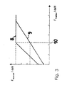
- the two drives 42 and 43 can be controlled independently of one another, it is particularly advantageous if, in the case of a standing material to be conveyed, which is to be conveyed by the sensor 7 above the drive unit 1, the second drive 43 is first switched on and after the necessary pressing force has been reached the first drive 42 is switched on, which then generates the necessary traction force. If the material to be conveyed has been recognized as being already moved and is to be transported further, first the first drive 42 is switched on to generate the necessary traction force and then only the second drive 43 to achieve the maximum desired pressing force. This minimizes wear on the conveyor roller 4. Further advantages of the sensible combination of the independently controllable drives 42 and 43 are supported by FIG. 3. For example, if heavy goods are to be transported, greater traction will be required.
- the maximum pressure force can be limited after a nominal traction force 10 is reached (see function curve 8).
- the advantages of this controllability are that additional mechanical stress is averted from the drive unit 1 (low pressure force with light and / or dry goods to be conveyed) and safe transport of the goods to be conveyed even under poor conditions (high pressure force with heavy and / or wet goods to be conveyed).
- simple and secure locking is possible with light goods to be conveyed, since this is not raised above the possible locking height by excessive pressure forces.
- the proposed cargo loading system with the invention Drive units 1 to a so-called anti-slip control.
- the speed specified by the first drive 42 is significantly greater than that actual transport speed of the conveyed goods. Compensation is achieved by increasing the pressure force.
- the regulation expediently takes over the central unit, since the necessary information is brought together in it, such as distances between the drive units 1, set speed of the conveyor roller 4 and Magnitude of the pressing force that is generated by the second drive 43.
- FIGS. 4 and 5 again show a drive unit 1 as part of a conveyor device with driveless rollers 2 and drivable conveyor roller 4.
- the driveless rollers 2 are shown in dash-dotted lines.
- a conveyor device of the type according to the invention in practice consists of a plurality of driveless rollers 2 and drivable conveyor rollers 4, the drivable conveyor rollers 4 each lying between the idler rollers 2.
- the distance between successive conveyor rollers 4 is to be selected in an application-specific manner in such a way that a material to be transported is always contacted by at least one drivable conveyor roller 4. In terms of weight, the material to be conveyed is essentially carried by the idler rollers 2.
- a prerequisite for a conveying active state of the driven conveyor rollers 4 is that a Conveyed goods with a contactable surface for the driven conveyor roller 4 are located above the conveyor roller 4.
- the reason why the drivable conveyor roller 4 is to be below the conveying level 3 in the inactive state is that the conveyed goods would otherwise abut the conveying roller 4 protruding from the conveying level 3 if the conveyed goods along the conveying level 3 onto the drivable conveying roller 4 is moved, or represents an obstacle to rolling, if the conveyor roller 4 is in the inactive state at the level of the conveyor level 3.
- the conveyor rollers 4 are oriented differently and have smaller distances from one another than the dimensions of the material to be conveyed, at least three conveyor rollers 4 not lying along a straight line having to act simultaneously under the material to be conveyed.
- the structure of the drive units 1 is explained below using a diagram according to FIG. 4.
- the drivable conveyor roller 4 is rotatably mounted on a cylindrical base body 41.
- This base body 41 is rotatably mounted about an eccentric axis 412 which is eccentric to its axis of symmetry 411, the base body 41 being pivotally mounted vertically (out of the plane of the drawing) in an eccentric counter bearing 432 with respect to the eccentric axis 412 fixed to the housing.
- the conveyor roller 4 is formed on its peripheral surface as an elastomer or coated with an elastomer material.
- the rotational movement of the drivable conveyor roller 4 is brought about by a first drive 42, which is connected to its own control unit 421 (control and power electronics).
- the driving force is supplied from the first drive 42 to the conveyor roller 4 via a gear mechanism (not shown in FIG. 4). With the drive 42 in conjunction with its control unit 421, the conveyor roller 4 can be driven in opposite directions.
- the start-up of the conveyor roller 4 can be regulated in terms of acceleration, which in particular enables a gentle start-up.
- an approximately known conveying speed of the conveyed material which is calculated via the connections 5 of all drive units 1 from the above-mentioned central unit, it is possible to have the drivable conveying roller 4 each act on the conveyed material at a speed that is the same as this speed.
- the required speed is calculated by the cross-system central unit, which supplies the adapted control data by means of the data provided by the individual drive units 1 via the connections 5 (speed, pressure force and traction force of the conveyor roller 4 and measured values from the sensor 7).
- the material to be conveyed can in particular also be braked in a defined manner by reducing the rotational speed of the conveying roller 4 contacting the material to be conveyed. Even when the material to be conveyed is at a standstill, the pressing force which is applied by the second drive 43 can be maintained, as a result of which the material to be conveyed is secured against displacement.
- Fig. 6 shows the drivable conveyor roller 4 in a hatched sectional view.
- the conveyor roller 4 is rotatably mounted on the outer surface of a cylindrical base body 41 about its axis of symmetry 411.
- This base body 41 is in turn rotatably mounted about an eccentric axis 412 that is eccentric to its axis of symmetry 411, the base body 41 being vertically pivotably mounted in an eccentric counter bearing 432 with respect to the eccentric axis 412 fixed to the housing.
- the rotational movement of the drivable conveyor roller 4 is brought about by a first drive 42, which is connected to its own control unit 421 and is located outside the main body 41.
- the driving force is supplied from the first drive 42 to the conveyor roller 4 via a gear transmission, the first part of the gear transmission being designed as a planetary gear 425.
- the gear lying between the planetary gear 425 and the conveyor roller 4 has a shaft mounted in the eccentric axis 412 on the base body 41 with a pinion 422.
- the pinion 422 acts via a spur gear toothing on an output gear 423, which in turn - the base body 41 radially outwards radical - drives the conveyor roller 4.
- the driven wheel 423 meshes in a region of the conveyor roller 4 designed as a ring gear 424.
- the rotation of the base body 41 about its eccentric axis 412 causes the second drive 43, which in turn is connected to its own control unit 431 (control and power electronics).
- the transmission of the drive energy of the drive 43 also takes place via a gear transmission, among other things with a planetary gear 433 directly downstream of the drive 43.
- FIG. 7 Another advantageous kinematic embodiment of the drive unit 1 according to the invention is shown in FIG. 7. This differs from the diagram in FIG. 6 only in the spatial arrangement of the first first drive 42. As is often the case in the prior art, this is preferably accommodated within the conveyor roller 4.
- the peculiarity in this example is that the drive shaft in the interior of the base body 41 has been moved from the eccentric axis 412 into the axis of symmetry 411 and the pinion 422 (from FIG. 6) here as a sun gear which at the same time as the drive 42 inside the conveyor roller 4 arranged planetary gear 425 is executed.
- the planet gears of the planetary gear 425 - like the output gear 423 in FIG. 6 - also engage through corresponding recesses in the lateral surface of the base body 41 in the region of the conveyor roller 4 designed as a ring gear 424. All other elements relating to the second drive 43 and the mounting of the base body 41 in the eccentric counter bearing 432 are unchanged from FIG. 6. Only the control unit 421 is no longer directly associated with the drive 42, but is positioned directly next to the control unit 431 of the second drive 43. As a result, there are no functional changes with respect to the basic idea of the invention, but further advantages due to the local concentration of the control electronics, also in cooperation with the other electronic components (not shown in FIGS. 6 and 7), the self-test device 6 and the networked via the connections 5 central processing unit.
- the conveying speed and the conveying conditions (such as weight and coefficient of friction) of the Conveyed goods are both jerky power transmissions and slip between the Conveyor roller 4 and the material to be conveyed avoided, causing wear on the material to be conveyed contacting elastomeric surface material of the conveyor roller 4 significantly reduced becomes.
- Such a reduction in wear is only after an extremely long time Operating times a replacement of the worn conveyor roller upper material or Drive unit necessary.
Landscapes
- Engineering & Computer Science (AREA)
- Mechanical Engineering (AREA)
- Rollers For Roller Conveyors For Transfer (AREA)
- Control Of Conveyors (AREA)
- Delivering By Means Of Belts And Rollers (AREA)
- Branching, Merging, And Special Transfer Between Conveyors (AREA)
- Attitude Control For Articles On Conveyors (AREA)
- Feeding Of Articles To Conveyors (AREA)
Description
Mit der erfindungsgemäßen Anordnung ist es möglich, Andruck- und Traktionskraft der Förderrolle in Abhängigkeit vom erkannten Bewegungszustand des Fördergutes einzustellen und den Verschleiß der Förderrolle zu vermindern. Weiterhin kann das Fördergut unter einer definierten Andruckkraft der Förderrolle erforderlichenfalls in entgegengesetzte Richtungen bewegt werden, wobei Beschleunigungen und Verzögerungen möglich sind. Insbesondere kann das Fördergut mittels der Förderrolle im Stillstand auch gegen ein Verschieben in Förderrichtung gesichert werden. Die Andruckkraft der Förderrolle an das Fördergut wird außerdem bei Unebenheiten der Angriffsfläche des Fördergutes auf einem konstanten Wert gehalten.
- Fig. 1:
- den prinzipiellen Aufbau eines Frachtladesystems,
- Fig. 2:
- einen prinzipiellen Aufbau der erfindungsgemäßen Antriebseinheit 1,
- Fig. 3:
- ein Rampenfunktionsdiagramm,
- Fig. 4:
- die Draufsicht auf eine Antriebseinheit 1,
- Fig. 5:
- eine Seitenansicht von Fig. 4,
- Fig. 6:
- eine schematische Darstellung eines vorteilhaften kinematischen Aufbaus der Antriebseinheit 1 und
- Fig. 7:
- eine schematische Darstellung eines weiteren vorteilhaften kinematischen Aufbaus der Antriebseinheit 1.
Wie aus Fig. 2 ersichtlich, besteht eine Antriebseinheit 1 aus einer Förderrolle 4, einem ersten Antrieb 42, einem zweiten Antrieb 43, einer ersten Ansteuereinheit 421, einer zweiten Ansteuereinheit 431, einer Selbsttesteinrichtung 6, einem Sensor 7 und den Verbindungen 5 zur Vernetzung mit der Zentraleinheit.
Die Antriebe 42 und 43 sind dabei als bürstenlose Gleichstrommotoren ausgebildet. Diese bürstenlosen Gleichstrommotoren, deren Rotoren Permanentmagnete enthalten, sind bestens steuer- und regelbar, nämlich in der Drehzahl und der zu übertragenden Kraft. Dieses geschieht mit den ihnen jeweils zugeordneten Ansteuereinheiten 421 und 431. Mit dem so ausgeführten ersten Antrieb 42, der zur Erzeugung der Traktionskraft für das Fördergut vorgesehen ist, lassen sich sowohl verschiedene Motordrehzahlen und somit unterschiedliche Transportgeschwindigkeiten als auch durch einfache Umpolung einer Sollwertvorgabe die entgegengesetzte Drehrichtung realisieren.
Der zweite Antrieb 43, der zur Erzeugung der Andruckkraft (Förderrolle 4 gegen Fördergut) vorgesehen ist, wird nach der Erkennung eines Fördergutes durch den Sensor 7 zugeschaltet und hebt somit über ein Getriebe die Förderrolle 4 bis zum Erreichen der gewünschten Andruckkraft an und verharrt in dieser Lage. Hierbei kommt die Verwendung des bürstenlosen Gleichstrommotors besonders zum Tragen, da er sich durch eine geringe Leistungsaufnahme auszeichnet, nachdem die gewünschte Andruckkraft erreicht wurde und der Gleichstrommotor in dieser Lage zur Gewährleistung einer gleichbleibenden Andruckkraft verharrt. Durch die geringe Leistungsaufnahme tritt demzufolge eine geringe Temperaturerhöhung des zweiten Antriebes 43 ein, was wiederum zu einem geringen Thermalstreß führt.
Da die beiden Antriebe 42 und 43 unabhängig voneinander ansteuerbar sind, ist es besonders vorteilhaft, wenn bei einem vom Sensor 7 über der Antriebseinheit 1 erkannten stehenden Fördergut, welches befördert werden soll, zunächst der zweite Antrieb 43 eingeschaltet wird und, nachdem die notwendige Andruckkraft erreicht wurde, der erste Antrieb 42 zugeschaltet wird, der sodann die notwendige Traktionskraft erzeugt. Falls das Fördergut als bereits bewegt erkannt wurde und weitertransportiert werden soll, wird zunächst der erste Antrieb 42 zur Erzeugung der notwendigen Traktionskraft zugeschalte und dann erst der zweite Antrieb 43 zum Erreichen der maximal gewünschter Andruckkraft. Dadurch wird der Verschleiß der Förderrolle 4 minimiert.
Weitere Vorteile der sinnvollen Kombination der unabhängig voneinander ansteuerbarer Antriebe 42 und 43 werden durch Fig. 3 gestützt.
Soll zum Beispiel ein schweres Fördergut transportiert werden, wird eine größere Traktionskraft erforderlich sein. Diese ist jedoch nur aufzubringen, wenn bei gleichbleibendem Reibwert die Förderrolle 4 mit einer größeren Andruckkraft an das Fördergut gepreßt wird, wie es in Fig. 3 die Funktionskurve 8 zeigt. Das gleiche gilt sinngemäß auch umgekehrt bei leichtem Fördergut, wobei gemäß Fig. 3 die Funktionskurve 9 zur Anwendung kommt.
Dasselbe Verhalten ist gefordert, wenn bei gleichem Gewicht des Fördergutes unterschiedliche Reibwerte auftreten. Dies ist zum Beispiel durch nasses bzw. trockenes Fördergut gegeben, wobei entsprechend ein niedrigerer bzw. ein höherer Reibwert auftritt. Dadurch wird bei niedrigem Reibwert eine höhere Andruckkraft erforderlich (Funktionskurve 8) sowie bei höherem Reibwert eine niedrigere Andruckkraft nötig sein (Funktionskurve 9). Eine Begrenzung der maximalen Andruckkraft kann nach Erreichen einer Nenntraktionskraft 10 erfolgen (siehe Funktionskurve 8). Die Vorteile dieser Steuerbarkeit sind, daß man zusätzlichen mechanischen Streß von der Antriebseinheit 1 abwendet (niedrige Andruckkraft bei leichtem und/oder trockenem Fördergut) sowie sicheren Transport des Fördergutes auch bei schlechten Bedingungen gewährleistet (hohe Andruckkraft bei schwerem und/oder nassem Fördergut). Zudem wird eine einfache und sichere Verriegelung bei leichtem Fördergut möglich, da dieses nicht durch zu hohe Andruckkräfte über die mögliche Verriegelungshöhe angehoben wird.
Für den Betrieb und für die Wartung werden wichtige Daten, wie Förderrollengeschwindigkeit, Andruckkraft, Traktionskraft und Sensorfunktion, von der Selbsttesteinrichtung 6 erfaßt, kontrolliert und erforderlichenfalls gespeichert, wobei einzelne Daten, die nicht nur für die Funktion der Antriebseinheit 1, in der sie gewonnen wurden, von Interesse sind, über die Verbindungen 5 der Zentraleinheit zugeführt. Diese Testfunktionen werden sowohl beim Einschalten der Antriebseinheit 1 als auch während des Betriebes durchgeführt.
Der Aufbau der Antriebseinheiten 1 wird nachstehend anhand eines Schemas gemäß Fig. 4 erläutert. Die antreibbare Förderrolle 4 ist drehbar auf einem zylindrischen Grundkörper 41 gelagert. Dieser Grundkörper 41 ist um eine zu seiner Symmetrieachse 411 exzentrische Exzenterachse 412 drehbar gelagert, wobei der Grundkörper 41 bezüglich der gehäusefesten Exzenterachse 412 in einem Exzentergegenlager 432 vertikal (aus der Zeichnungsebene heraus) schwenkbar gelagert ist. Die Förderrolle 4 ist auf ihrer Umfangsfläche als ein Elastomer ausgebildet oder mit einem Elastomermaterial überzogen.
Die Rotationsbewegung der antreibbaren Förderrolle 4 wird von einem ersten Antrieb 42 bewirkt, der mit einer eigenen Ansteuereinheit 421 (Steuerungs- und Leistungselektronik) verbunden ist. Die Antriebskraft wird von dem ersten Antrieb 42 über ein (in Fig. 4 nicht dargestelltes) Zahnradgetriebe der Förderrolle 4 zugeleitet. Mit dem Antrieb 42 kann in Verbindung mit dessen Ansteuereinheit 421 die Förderrolle 4 in entgegengesetzten Richtungen angetrieben werden. Der Anlauf der Förderrolle 4 kann beschleunigungsmäßig geregelt werden, wodurch insbesondere ein sanfter Anlauf möglich ist.
Bei einer in etwa bekannten Fördergeschwindigkeit des Fördergutes, die über die Verbindungen 5 aller Antriebseinheiten 1 von der oben erwähnten Zentralenheit berechnet wird, ist es möglich, die antreibbare Förderrolle 4 jeweils mit einer zu dieser Geschwindigkeit gleichen Geschwindigkeit an dem Fördergut angreifen zu lassen. Dabei wird die erforderliche Geschwindigkeit von der systemübergreifenden Zentraleinheit, die mittels der über die Verbindungen 5 von den einzelnen Antriebseinheiten 1 bereitgestellten Daten (Geschwindigkeit, Andruckkraft und Traktionskraft der Förderrolle 4 sowie Meßwerte des Sensors 7) versorgt, die angepaßten Ansteuerdaten berechnet.
Das Fördergut kann durch eine Reduzierung der Drehgeschwindigkeit der das Fördergut kontaktierenden Förderrolle 4 insbesondere auch definiert gebremst werden. Auch im Stillstand des Fördergutes kann die Andruckkraft, die von dem zweiten Antrieb 43 aufgebracht wird, erhalten bleiben, wodurch das Fördergut gegen Verschieben gesichert ist.
Die Rotationsbewegung der antreibbaren Förderrolle 4 wird von einem ersten Antrieb 42 bewirkt, der mit einer eigenen Ansteuereinheit 421 verbunden ist und sich außerhalb des Grundkörpers 41 befindet. Die Antriebskraft wird von dem ersten Antrieb 42 über ein Zahnradgetriebe der Förderrolle 4 zugeleitet, wobei der erste Teil des Zahnradgetriebes als ein Planetengetriebe 425 ausgebildet ist.
Das zwischen dem Planetengetriebe 425 und der Förderrolle 4 liegende Getriebe besitzt eine in der Exzenterachse 412 an dem Grundkörper 41 gelagerte Welle mit einem Ritzel 422. Das Ritzel 422 wirkt über eine Stirnradverzahnung auf ein Abtriebszahnrad 423 ein, das wiederum - den Grundkörper 41 radial nach außen durchgreifend - die Förderrolle 4 antreibt. Das Abtriebsrad 423 kämmt dabei in einem als Hohlrad 424 ausgebildeten Bereich der Förderrolle 4.
Die Drehung des Grundkörpers 41 um dessen Exzenterachse 412 bewirkt der zweite Antrieb 43, der wiederum mit einer eigenen Ansteuereinheit 431 (Steuerungs- und Leistungselektronik) verbunden ist. Die Übertragung der Antriebsenergie des Antriebs 43 erfolgt ebenfalls über ein Zahnradgetriebe unter anderem mit einem dem Antrieb 43 direkt nachgeordneten Planetengetriebe 433.
Eine weitere vorteilhafte kinematische Ausfürungsform der erfindungsmäßen Antriebseinheit 1 ist in Fig. 7 dargestellt. Diese unterscheidet sich von dem Schema in Fig. 6 lediglich in der räumlichen Anordnung des ersten ersten Antriebs 42. Dieser ist hier wie häufig im Stand der Technik bevorzugt innerhalb der Förderrolle 4 untergebracht. Die Besonderheit besteht in diesem Beispiel darin, daß die Antriebswelle im Innern des Grundkörpers 41 von der Exzenterachse 412 in die Symmetrieachse 411 verlegt wurde und das Ritzel 422 (von Fig. 6) hier als Sonnenrad des zugleich mit dem Antrieb 42 im Innern der Förderrolle 4 angeordneten Planetengetriebes 425 ausgeführt ist. Die Planetenräder der Planetengetriebes 425 greifen - wie in Fig. 6 das Abtriebszahnrad 423 - ebenfalls durch entsprechende Ausnehmungen in der Mantelfläche des Grundkörpers 41 hindurch in den als Hohlrad 424 ausgebildeten Bereich der Förderrolle 4 ein. Alle übrigen Elemente, die den zweiten Antrieb 43 sowie die Lagerung des Grundkörpers 41 im Exzentergegenlager 432 betreffen sind gegenüber Fig. 6 unverändert. Lediglich die Ansteuereinheit 421 ist nicht mehr direkt dem Antrieb 42 beigeordnet, sondern unmittelbar neben der Ansteuereinheit 431 des zweiten Antriebs 43 positioniert.
Dadurch ergeben sich bezüglich der erfindungsgemäßen Grundidee der Erfindung keinerlei funktionelle Veränderungen, sondern weitere Vorteile durch örtliche Konzentration der Steuerelektronik auch im Zusammenwirken mit den weiteren (in Fig. 6 und 7 nicht dargestellten) elektronischen Komponenten, der Selbsttesteinrichtung 6 und der über die Verbindungen 5 vernetzten Zentraleinheit.
- 1
- Antriebseinheit
- 2
- (antriebslose) Laufrolle
- 3
- Förderebene
- 4
- (antreibbare) Förderrolle
- 41
- Grundkörper
- 411
- Symmertrieachse
- 412
- Exzenterachse
- 42
- erster Antrieb
- 421
- Ansteuereinheit
- 422
- Ritzel
- 423
- Abtriebszahnrad
- 424
- Hohlrad
- 425
- Planetengetriebe
- 43
- zweiter Antrieb
- 431
- Ansteuereinheit
- 432
- Exzentergegenlager
- 433
- Planetengetriebe
- 5
- Verbindung zur Zentraleinheit
- 6
- Selbsttesteinrichtung
- 7
- Sensoreinheit
- 8,9
- Funktionskurve
- 10
- Nenntraktionskraft
Claims (12)
- Anordnung zum Bewegen eines Fördergutes entlang einer Förderebene, die durch antriebslose, zum Tragen und Führen eines Fördergutes dienende Laufrollen (2) gebildet wird, mit einer antreibbaren Förderrolle (4), die zwischen den antriebslosen Laufrollen (2) angeordnet ist, und einer Steuerelektronik zur Steuerung eines die Förderrolle (4) treibenden Antriebs (42 und 43) mit folgenden weiteren Merkmalena) die Förderrolle (4) steht mit einem ersten Antrieb (42) und zugeordneter erster Ansteuereinheit (421) zur Erzeugung einer notwendigen Traktionskraft zum Bewegen des Fördergutes entlang der Förderebene (3) in Verbindung,b) ein zweiter Antrieb (43) mit zugeordneter zweiter Ansteuereinheit (431) ist zur Erzeugung einer ausreichenden Andruckkraft der Förderrolle (4) gegen das Fördergut vorhanden,c) die beiden unabhängig voneinander ansteuerbaren Antriebe (42, 43) sind von der Steuerelektronik koordiniert angesteuert,d) die Förderrolle (4) ist in der Form eines Hohlzylinders auf einem zylindrischen Grundkörper (41) um dessen Symmetrieachse (411) drehbar gelagert, wobei sich das Getriebe für den ersten Antrieb (42) innerhalb des Grundkörpers (41) befindet,e) zur Kraftübertragung vom zweiten Antrieb (43) auf den Grundkörper (41) ist ein Zahnradgetriebe eingesetzt,f) der Grundkörper (41) ist um eine parallel zu seiner Symmetrieachse (411) verlaufende Exzenterachse (412) drehbar gelagert,g) der zweite Antrieb (43) ist mit dem Grundkörper (41) zum Ausschwenken des Grundkörpers (41) um dessen Exzenterachse (412) und Andrücken der Förderrolle (4) an das Fördergut auf der Förderebene (3) gekoppelt,h) zur Kraftübertragung vom ersten Antrieb (42) auf die Förderrolle (4) ist ein Zahnradgetriebe eingesetzt,i) das die Förderrolle (4) antreibende Getriebe weist ein in der Exzenterachse (412) des zylindrischen Grundkörpers (41) gelagertes Ritzel (422) auf, das mit dem ersten Antrieb (42) in Verbindung steht und innerhalb des zylindrischen Grundkörpers (41) liegt,k) ein radial zwischen diesem Ritzel (422) und der Förderrolle (4) achsparallel drehbar gelagertes Abtriebsrad (423) ist vorhanden, das den Grundkörper (41) radial nach außen überragend in einen als Hohlrad (424) ausgebildeten Bereich der Förderrolle (4) kämmend eingreift.
- Anordnung zum Bewegen eines Fördergutes entlang einer Förderebene, die durch antriebslose, zum Tragen und Führen eines Fördergutes dienende Laufrollen (2) gebildet wird, mit einer antreibbaren Förderrolle (4), die zwischen den antriebslosen Laufrollen (2) angeordnet ist, und einer Steuerelektronik zur Steuerung eines die Förderrolle (4) treibenden Antriebs (42 und 43) mit folgenden weiteren Merkmalena) die Förderrolle (4) steht mit einem ersten Antrieb (42) und zugeordneter erster Ansteuereinheit (421) zur Erzeugung einer notwendigen Traktionskraft zum Bewegen des Fördergutes entlang der Förderebene (3) in Verbindung,b) ein zweiter Antrieb (43) mit zugeordneter zweiter Ansteuereinheit (431) ist zur Erzeugung einer ausreichenden Andruckkraft der Förderrolle (4) gegen das Fördergut vorhanden,c) die beiden unabhängig voneinander ansteuerbaren Antriebe (42, 43) sind von der Steuerelektronik koordiniert angesteuert,d) die Förderrolle (4) ist in der Form eines Hohlzylinders auf einem zylindrischen Grundkörper (41) um dessen Symmetrieachse (411) drehbar gelagert, wobei sich das Getriebe für den ersten Antrieb (42) innerhalb des Grundkörpers (41) befindet,e) zur Kraftübertragung vom zweiten Antrieb (43) auf den Grundkörper (41) ist ein Zahnradgetriebe eingesetzt,f) der Grundkörper (41) ist um eine parallel zu seiner Symmetrieachse (411) verlaufende Exzenterachse (412) drehbar gelagert,g) der zweite Antrieb (43) ist mit dem Grundkörper (41) zum Ausschwenken des Grundkörpers (41) um dessen Exzenterachse (412) und Andrücken der Förderrolle (4) an das Fördergut auf der Förderebene (3) gekoppelt,h) zur Kraftübertragung vom ersten Antrieb (42) auf die Förderrolle (4) ist ein Zahnradgetriebe eingesetzt,i) das die Förderrolle (4) antreibende Getriebe ist zwischen dem ersten Antrieb (42) und der Förderrolle (4) zumindest in einem Teilbereich als Planetengetriebe (425) ausgebildet, undk) das die Förderrolle (4) antreibende Getriebe mit dem Planetengetriebe (425) sowie der erste Antrieb (42) sind innerhalb des Grundkörpers (41) angeordnet, wobei das Sonnenrad des Planetengetriebes (425) auf der Symmetrieachse (411) des Grundkörpers (41) angeordnet ist und die Planetenräder in einem als Hohlrad (424) ausgebildeten Bereich der Förderrolle (4) kämmen.
- Anordnung nach Anspruch 1 oder 2,
dadurch gekennzeichnet, dass zum Ausschwenken des Grundkörpers (41) in die Förderebene (3) zwischen dem zweiten Antrieb (43) und dem Grundkörper (41) ein zumindest in einem Teilbereich als Planetengetriebe ausgebildetes Zahnradgetriebe vorgesehen ist. - Anordnung nach einem der vorhergehenden Ansprüche,
dadurch gekennzeichnet, dass mindestens der zweite Antrieb (43) zur Einstellung vorbestimmbarer Andruckkräfte der Förderrolle (4) gegen das Fördergut bezüglich seines Antriebsmomentes regelbar ist. - Anordnung nach Anspruch 4,
dadurch gekennzeichnet, dass der erste und der zweite Antrieb (42, 43) als regelbare Servomotoren ausgebildet sind. - Anordnung nach Anspruch 5,
dadurch gekennzeichnet, dass die Antriebe (42, 43) bürstenlose Gleichstrommotoren sind. - Anordnung nach einem der vorhergehenden Ansprüche,
dadurch gekennzeichnet, dass die Steuerelektronik eine Sensoreinheit (7) zum Erkennen des Fördergutes und eine Selbsttesteinrichtung (6) enthält, die die beiden unabhängigen Antriebe (42, 43) in Abhängigkeit von einem mindestens mittels der internen Sensoreinheit (7) erkannten Bewegungszustand des Fördergutes steuert. - Anordnung nach Anspruch 7,
dadurch gekennzeichnet, dass die Selbsttesteinrichtung (6) mit der Sensoreinheit (7) in Verbindung steht, wobei in Abhängigkeit vom erkannten stehenden oder bewegten Zustand des Fördergutes alternativ zunächst der zweite Antrieb (43) vor dem Zuschalten des ersten (42) oder zuerst der erste Antrieb (42) vor dem Zuschalten des zweiten (43) über die Ansteuereinheiten (421, 431) ansteuerbar ist. - Anordnung nach Anspruch 6 oder 7,
dadurch gekennzeichnet, dass die Selbsttesteinrichtung (6) über Verbindungen (5) zur Übermittlung von gewonnenen Daten, wie Andruckkraft, Traktionskraft, Sensorfunktion und Drehgeschwindigkeit der Förderrolle (4) mit einer Zentraleinheit in Verbindung steht. - Anordnung nach Anspruch 9,
dadurch gekennzeichnet, dass in der Selbsttesteinrichtung (6) Mittel zur Antischlupfregelung vorgesehen sind, wobei über die Zentraleinheit mittels der gewonnen Daten aus verschiedenen Antriebseinheiten (1), der Kenntnis der genauen Abstände der Antriebseinheiten (1) sowie der Kenntnis der Drehgeschwindigkeit der Förderrolle (4) und der realen Transportgeschwindigkeit des Fördergutes ein entstehender Schlupf durch gezielte Erhöhung der Andruckkraft kompensierbar ist.
Applications Claiming Priority (4)
| Application Number | Priority Date | Filing Date | Title |
|---|---|---|---|
| DE19817713 | 1998-04-21 | ||
| DE1998117713 DE19817713A1 (de) | 1998-04-21 | 1998-04-21 | Förderrollen-Antrieb |
| DE19818522 | 1998-04-24 | ||
| DE1998118522 DE19818522A1 (de) | 1998-04-24 | 1998-04-24 | Frachtladesystem |
Publications (2)
| Publication Number | Publication Date |
|---|---|
| EP0952096A1 EP0952096A1 (de) | 1999-10-27 |
| EP0952096B1 true EP0952096B1 (de) | 2002-11-13 |
Family
ID=26045649
Family Applications (1)
| Application Number | Title | Priority Date | Filing Date |
|---|---|---|---|
| EP99107356A Expired - Lifetime EP0952096B1 (de) | 1998-04-21 | 1999-04-21 | Anordnung zum Bewegen eines Fördergutes entlang einer Förderebene |
Country Status (4)
| Country | Link |
|---|---|
| US (1) | US6279730B1 (de) |
| EP (1) | EP0952096B1 (de) |
| AT (1) | ATE227684T1 (de) |
| DE (1) | DE59903371D1 (de) |
Families Citing this family (8)
| Publication number | Priority date | Publication date | Assignee | Title |
|---|---|---|---|---|
| ATE517056T1 (de) * | 2001-03-29 | 2011-08-15 | Ancra Int Llc | Frachtkraftantriebseinheit |
| DE602004009053T2 (de) * | 2003-05-02 | 2008-06-12 | Ancra International, LLC, Hawthorne | Lenkbare /einziehbare frachtkraftantriebseinheit |
| TWD107385S1 (zh) * | 2004-07-20 | 2005-11-01 | 東京威力科創股份有限公司 | 晶圓搬運機 |
| DE102005008443B4 (de) * | 2005-02-24 | 2009-06-18 | Airbus Deutschland Gmbh | Ladevorrichtung zum zumindest teilautomatischen Beladen und Entladen eines Frachtraums eines Verkehrsmittels |
| DE102005030058A1 (de) * | 2005-06-27 | 2007-01-04 | Wittenstein Ag | Vorrichtung zum Transportieren von Frachtgut |
| US8109702B2 (en) * | 2008-08-28 | 2012-02-07 | Goodrich Corporation | Attenuated cargo caster |
| DE102011000820B4 (de) * | 2011-02-18 | 2012-09-06 | Telair International Gmbh | Frachtladesystem und Verfahren zur Steuerung einer Vielzahl von Frachtfördereinrichtungen |
| US9925906B1 (en) * | 2016-09-23 | 2018-03-27 | Philip L. Hoy | Self-unloading pipe trailer |
Citations (1)
| Publication number | Priority date | Publication date | Assignee | Title |
|---|---|---|---|---|
| EP0937661A1 (de) * | 1998-02-20 | 1999-08-25 | Telair International GmbH | Antriebsrolleneinheit |
Family Cites Families (14)
| Publication number | Priority date | Publication date | Assignee | Title |
|---|---|---|---|---|
| DE6910760U (de) | 1969-03-18 | 1970-09-10 | Noltemeyer Ludwig Fr | Vorrichtung zum vorbehandeln einer schlauchfolie |
| US3709450A (en) * | 1970-12-11 | 1973-01-09 | Boeing Co | Cargo loading system for aircraft |
| US3978975A (en) | 1975-06-30 | 1976-09-07 | The Boeing Company | Cargo power drive unit |
| US4589542A (en) | 1983-12-19 | 1986-05-20 | The Boeing Company | Cargo drive unit |
| DE3911214C3 (de) | 1989-04-06 | 1995-02-23 | Telair Int Cargo Sys Gmbh | Rollenantriebseinheit |
| US5042645A (en) * | 1990-10-18 | 1991-08-27 | Teleflex Incorporated | Dual motor cargo drive unit |
| EP0497045B1 (de) | 1991-01-30 | 1995-02-22 | Teleflex Incorporated | Rollenantriebseinheit für eine Förderbahn |
| US5186417A (en) | 1991-05-03 | 1993-02-16 | Teleflex Incorporated | Aircraft cargo control system |
| DE4136972C2 (de) | 1991-11-11 | 1994-05-11 | Deutsche Aerospace Airbus | Vorrichtung zum Transportieren von Lasten in Flugzeugfrachträumen |
| US5183150A (en) * | 1991-12-13 | 1993-02-02 | Allied-Signal Inc. | Cargo drive unit with a hysteresis coupling |
| DE4427696C2 (de) | 1994-08-04 | 1997-06-12 | Telair Int Cargo Sys Gmbh | Verfahren und Ladesystem zum Beladen eines Frachtraums in einem Flugzeug |
| US5803234A (en) | 1996-03-01 | 1998-09-08 | Ancra International Corporation | Roller drive system for vehicle conveyor |
| DE19608236C1 (de) | 1996-03-04 | 1997-05-22 | Jarl Dipl Ing Sundseth | Rollenantriebseinheit |
| DE19807229C2 (de) | 1998-02-20 | 1999-12-23 | Telair Int Gmbh | Rollenantriebseinheit und Ladesystem mit Sensoren und einer Steuerlogik, insbesondere zum motorgetriebenen Anheben und Absenken der Antriebsrollen von Rollenantriebseinheiten |
-
1999
- 1999-04-20 US US09/294,478 patent/US6279730B1/en not_active Expired - Fee Related
- 1999-04-21 EP EP99107356A patent/EP0952096B1/de not_active Expired - Lifetime
- 1999-04-21 AT AT99107356T patent/ATE227684T1/de not_active IP Right Cessation
- 1999-04-21 DE DE59903371T patent/DE59903371D1/de not_active Expired - Lifetime
Patent Citations (1)
| Publication number | Priority date | Publication date | Assignee | Title |
|---|---|---|---|---|
| EP0937661A1 (de) * | 1998-02-20 | 1999-08-25 | Telair International GmbH | Antriebsrolleneinheit |
Also Published As
| Publication number | Publication date |
|---|---|
| EP0952096A1 (de) | 1999-10-27 |
| US6279730B1 (en) | 2001-08-28 |
| ATE227684T1 (de) | 2002-11-15 |
| DE59903371D1 (de) | 2002-12-19 |
Similar Documents
| Publication | Publication Date | Title |
|---|---|---|
| EP2736822B1 (de) | Fördereinrichtung mit einem flächig ausgedehnten förderorgan | |
| DE602004009053T2 (de) | Lenkbare /einziehbare frachtkraftantriebseinheit | |
| DE112020000999T5 (de) | Achsanordnung für Niederflurfahrzeuge | |
| EP0595122A1 (de) | Reibradantrieb für eine Personentransporteinrichtung | |
| EP1676057B1 (de) | Getriebevorrichtung und verfahren zum steuern und regeln einer getriebevorrichtung | |
| DE102019108759B4 (de) | Bodenbearbeitungsmaschine | |
| DE1550654B1 (de) | Vorrichtung zum UEbertragen eines biegsamen Zugmittels auf einen Stuetzkoerper | |
| DE102013016707B4 (de) | Transportvorrichtung und Bestückvorrichtung damit | |
| AT405270B (de) | Seilbahnanlage | |
| EP0952096A1 (de) | Anordnung zum Bewegen eines Fördergutes entlang einer Förderebene | |
| DE102020120413A1 (de) | Radsatztransporteinheit für das Bewegen eines Radsatzes auf einem Gleis, Anordnung und Verfahren | |
| DE3408351A1 (de) | Tochterdrehvorrichtung fuer mechanische greifer eines foerderkrans | |
| DE10327423B4 (de) | Antrieb für eine Rotationsdruckmaschine | |
| DE19900461A1 (de) | Transportvorrichtung | |
| WO2022223610A1 (de) | Fahrantrieb | |
| EP0933314A2 (de) | Kanalfahrzeug für ein automatisches Lager | |
| WO2017149066A1 (de) | Linearmotoranordnung für eine aufzugsanlage | |
| CH706033A1 (de) | Fördereinrichtung mit einem flächig ausgedehnten Förderorgan. | |
| DE10051758B4 (de) | Positioniervorrichtung und deren Arbeitsverfahren | |
| WO1998051601A1 (de) | Aufwickelvorrichtung für papierbahnen und verfahren zum aufwickeln von papierbahnen | |
| DE20022495U1 (de) | Positioniervorrichtung | |
| DE102021206820B4 (de) | Fahrerloses Transportfahrzeug mit Nebenabtrieb, Ladungsträger und Fördersystem | |
| DE8812338U1 (de) | Fördervorrichtung | |
| WO2000037276A1 (de) | Getriebe mit stufenlos variablem übersetzungsverhältnis und verfahren zur verteilung eines drehmomentes auf ausgangswellen | |
| DE69315867T2 (de) | Drehmaschine für Eisenbahnräder |
Legal Events
| Date | Code | Title | Description |
|---|---|---|---|
| PUAI | Public reference made under article 153(3) epc to a published international application that has entered the european phase |
Free format text: ORIGINAL CODE: 0009012 |
|
| AK | Designated contracting states |
Kind code of ref document: A1 Designated state(s): AT DE ES FR GB IT |
|
| AX | Request for extension of the european patent |
Free format text: AL;LT;LV;MK;RO;SI |
|
| 17P | Request for examination filed |
Effective date: 19991224 |
|
| AKX | Designation fees paid |
Free format text: AT DE FR GB |
|
| RBV | Designated contracting states (corrected) |
Designated state(s): AT BE CH DE FR GB LI |
|
| RBV | Designated contracting states (corrected) |
Designated state(s): AT DE ES FR GB IT |
|
| 17Q | First examination report despatched |
Effective date: 20000801 |
|
| RBV | Designated contracting states (corrected) |
Designated state(s): DE ES FR GB IT |
|
| RBV | Designated contracting states (corrected) |
Designated state(s): AT DE ES FR GB IT |
|
| GRAG | Despatch of communication of intention to grant |
Free format text: ORIGINAL CODE: EPIDOS AGRA |
|
| RAP1 | Party data changed (applicant data changed or rights of an application transferred) |
Owner name: WITTENSTEIN MOTION CONTROL GMBH Owner name: JENOPTIK AKTIENGESELLSCHAFT |
|
| GRAG | Despatch of communication of intention to grant |
Free format text: ORIGINAL CODE: EPIDOS AGRA |
|
| GRAH | Despatch of communication of intention to grant a patent |
Free format text: ORIGINAL CODE: EPIDOS IGRA |
|
| GRAH | Despatch of communication of intention to grant a patent |
Free format text: ORIGINAL CODE: EPIDOS IGRA |
|
| GRAA | (expected) grant |
Free format text: ORIGINAL CODE: 0009210 |
|
| AK | Designated contracting states |
Kind code of ref document: B1 Designated state(s): AT DE ES FR GB IT |
|
| PG25 | Lapsed in a contracting state [announced via postgrant information from national office to epo] |
Ref country code: IT Free format text: LAPSE BECAUSE OF FAILURE TO SUBMIT A TRANSLATION OF THE DESCRIPTION OR TO PAY THE FEE WITHIN THE PRESCRIBED TIME-LIMIT;WARNING: LAPSES OF ITALIAN PATENTS WITH EFFECTIVE DATE BEFORE 2007 MAY HAVE OCCURRED AT ANY TIME BEFORE 2007. THE CORRECT EFFECTIVE DATE MAY BE DIFFERENT FROM THE ONE RECORDED. Effective date: 20021113 |
|
| REF | Corresponds to: |
Ref document number: 227684 Country of ref document: AT Date of ref document: 20021115 Kind code of ref document: T |
|
| REG | Reference to a national code |
Ref country code: GB Ref legal event code: FG4D Free format text: NOT ENGLISH |
|
| GBT | Gb: translation of ep patent filed (gb section 77(6)(a)/1977) |
Effective date: 20021113 |
|
| REF | Corresponds to: |
Ref document number: 59903371 Country of ref document: DE Date of ref document: 20021219 |
|
| ET | Fr: translation filed | ||
| PG25 | Lapsed in a contracting state [announced via postgrant information from national office to epo] |
Ref country code: AT Free format text: LAPSE BECAUSE OF NON-PAYMENT OF DUE FEES Effective date: 20030421 |
|
| PG25 | Lapsed in a contracting state [announced via postgrant information from national office to epo] |
Ref country code: ES Free format text: LAPSE BECAUSE OF FAILURE TO SUBMIT A TRANSLATION OF THE DESCRIPTION OR TO PAY THE FEE WITHIN THE PRESCRIBED TIME-LIMIT Effective date: 20030529 |
|
| PLBE | No opposition filed within time limit |
Free format text: ORIGINAL CODE: 0009261 |
|
| STAA | Information on the status of an ep patent application or granted ep patent |
Free format text: STATUS: NO OPPOSITION FILED WITHIN TIME LIMIT |
|
| 26N | No opposition filed |
Effective date: 20030814 |
|
| REG | Reference to a national code |
Ref country code: GB Ref legal event code: 732E |
|
| REG | Reference to a national code |
Ref country code: FR Ref legal event code: TP |
|
| PGFP | Annual fee paid to national office [announced via postgrant information from national office to epo] |
Ref country code: FR Payment date: 20100506 Year of fee payment: 12 |
|
| PGFP | Annual fee paid to national office [announced via postgrant information from national office to epo] |
Ref country code: GB Payment date: 20100420 Year of fee payment: 12 Ref country code: DE Payment date: 20100629 Year of fee payment: 12 |
|
| REG | Reference to a national code |
Ref country code: DE Ref legal event code: R119 Ref document number: 59903371 Country of ref document: DE |
|
| REG | Reference to a national code |
Ref country code: DE Ref legal event code: R119 Ref document number: 59903371 Country of ref document: DE |
|
| GBPC | Gb: european patent ceased through non-payment of renewal fee |
Effective date: 20110421 |
|
| REG | Reference to a national code |
Ref country code: FR Ref legal event code: ST Effective date: 20111230 |
|
| PG25 | Lapsed in a contracting state [announced via postgrant information from national office to epo] |
Ref country code: FR Free format text: LAPSE BECAUSE OF NON-PAYMENT OF DUE FEES Effective date: 20110502 |
|
| PG25 | Lapsed in a contracting state [announced via postgrant information from national office to epo] |
Ref country code: GB Free format text: LAPSE BECAUSE OF NON-PAYMENT OF DUE FEES Effective date: 20110421 |
|
| PG25 | Lapsed in a contracting state [announced via postgrant information from national office to epo] |
Ref country code: DE Free format text: LAPSE BECAUSE OF NON-PAYMENT OF DUE FEES Effective date: 20111031 |