EP0951345B1 - Fluid mixer and process using the same - Google Patents
Fluid mixer and process using the same Download PDFInfo
- Publication number
- EP0951345B1 EP0951345B1 EP98905287A EP98905287A EP0951345B1 EP 0951345 B1 EP0951345 B1 EP 0951345B1 EP 98905287 A EP98905287 A EP 98905287A EP 98905287 A EP98905287 A EP 98905287A EP 0951345 B1 EP0951345 B1 EP 0951345B1
- Authority
- EP
- European Patent Office
- Prior art keywords
- expander
- sectional area
- cross
- downstream
- upstream
- Prior art date
- Legal status (The legal status is an assumption and is not a legal conclusion. Google has not performed a legal analysis and makes no representation as to the accuracy of the status listed.)
- Expired - Lifetime
Links
- 239000012530 fluid Substances 0.000 title claims abstract description 68
- 238000000034 method Methods 0.000 title claims abstract description 32
- 238000011144 upstream manufacturing Methods 0.000 claims abstract description 42
- 238000006243 chemical reaction Methods 0.000 claims abstract description 26
- 239000003054 catalyst Substances 0.000 claims abstract description 24
- 238000004880 explosion Methods 0.000 claims abstract description 14
- 238000007254 oxidation reaction Methods 0.000 claims abstract description 12
- 230000003647 oxidation Effects 0.000 claims abstract description 11
- 230000036961 partial effect Effects 0.000 claims abstract description 11
- 239000004215 Carbon black (E152) Substances 0.000 claims abstract description 8
- 229930195733 hydrocarbon Natural products 0.000 claims abstract description 8
- 150000002430 hydrocarbons Chemical class 0.000 claims abstract description 8
- 238000002485 combustion reaction Methods 0.000 claims abstract description 7
- 230000003197 catalytic effect Effects 0.000 claims abstract description 6
- 239000007789 gas Substances 0.000 claims description 15
- QVGXLLKOCUKJST-UHFFFAOYSA-N atomic oxygen Chemical compound [O] QVGXLLKOCUKJST-UHFFFAOYSA-N 0.000 claims description 9
- 239000001301 oxygen Substances 0.000 claims description 9
- 229910052760 oxygen Inorganic materials 0.000 claims description 9
- 229910052799 carbon Inorganic materials 0.000 claims description 3
- 230000004323 axial length Effects 0.000 claims description 2
- 238000009792 diffusion process Methods 0.000 description 6
- 239000000463 material Substances 0.000 description 6
- VNWKTOKETHGBQD-UHFFFAOYSA-N methane Chemical compound C VNWKTOKETHGBQD-UHFFFAOYSA-N 0.000 description 6
- MCMNRKCIXSYSNV-UHFFFAOYSA-N Zirconium dioxide Chemical compound O=[Zr]=O MCMNRKCIXSYSNV-UHFFFAOYSA-N 0.000 description 4
- 239000000203 mixture Substances 0.000 description 4
- 239000000758 substrate Substances 0.000 description 4
- VYPSYNLAJGMNEJ-UHFFFAOYSA-N Silicium dioxide Chemical compound O=[Si]=O VYPSYNLAJGMNEJ-UHFFFAOYSA-N 0.000 description 2
- GWEVSGVZZGPLCZ-UHFFFAOYSA-N Titan oxide Chemical compound O=[Ti]=O GWEVSGVZZGPLCZ-UHFFFAOYSA-N 0.000 description 2
- 230000000694 effects Effects 0.000 description 2
- 230000003628 erosive effect Effects 0.000 description 2
- 239000000835 fiber Substances 0.000 description 2
- 239000006260 foam Substances 0.000 description 2
- 231100001261 hazardous Toxicity 0.000 description 2
- 230000000670 limiting effect Effects 0.000 description 2
- 229910001092 metal group alloy Inorganic materials 0.000 description 2
- 239000003345 natural gas Substances 0.000 description 2
- 230000002829 reductive effect Effects 0.000 description 2
- 238000003892 spreading Methods 0.000 description 2
- 230000006641 stabilisation Effects 0.000 description 2
- UGFAIRIUMAVXCW-UHFFFAOYSA-N Carbon monoxide Chemical compound [O+]#[C-] UGFAIRIUMAVXCW-UHFFFAOYSA-N 0.000 description 1
- UFHFLCQGNIYNRP-UHFFFAOYSA-N Hydrogen Chemical compound [H][H] UFHFLCQGNIYNRP-UHFFFAOYSA-N 0.000 description 1
- 239000011149 active material Substances 0.000 description 1
- 230000006978 adaptation Effects 0.000 description 1
- HSFWRNGVRCDJHI-UHFFFAOYSA-N alpha-acetylene Natural products C#C HSFWRNGVRCDJHI-UHFFFAOYSA-N 0.000 description 1
- PNEYBMLMFCGWSK-UHFFFAOYSA-N aluminium oxide Inorganic materials [O-2].[O-2].[O-2].[Al+3].[Al+3] PNEYBMLMFCGWSK-UHFFFAOYSA-N 0.000 description 1
- 230000015572 biosynthetic process Effects 0.000 description 1
- 229910002091 carbon monoxide Inorganic materials 0.000 description 1
- 239000012876 carrier material Substances 0.000 description 1
- 239000000567 combustion gas Substances 0.000 description 1
- 238000010960 commercial process Methods 0.000 description 1
- 230000003750 conditioning effect Effects 0.000 description 1
- 239000012084 conversion product Substances 0.000 description 1
- 230000007423 decrease Effects 0.000 description 1
- 230000018109 developmental process Effects 0.000 description 1
- 230000009699 differential effect Effects 0.000 description 1
- 125000002534 ethynyl group Chemical group [H]C#C* 0.000 description 1
- 239000004744 fabric Substances 0.000 description 1
- 239000001257 hydrogen Substances 0.000 description 1
- 229910052739 hydrogen Inorganic materials 0.000 description 1
- 229910001026 inconel Inorganic materials 0.000 description 1
- 229910010272 inorganic material Inorganic materials 0.000 description 1
- 239000011147 inorganic material Substances 0.000 description 1
- 239000007788 liquid Substances 0.000 description 1
- 238000004519 manufacturing process Methods 0.000 description 1
- 239000011159 matrix material Substances 0.000 description 1
- 229910052751 metal Inorganic materials 0.000 description 1
- 239000002184 metal Substances 0.000 description 1
- 238000005192 partition Methods 0.000 description 1
- 239000011148 porous material Substances 0.000 description 1
- 239000000047 product Substances 0.000 description 1
- 230000002787 reinforcement Effects 0.000 description 1
- 230000000717 retained effect Effects 0.000 description 1
- 238000000926 separation method Methods 0.000 description 1
- 239000000377 silicon dioxide Substances 0.000 description 1
- 239000010935 stainless steel Substances 0.000 description 1
- 229910001220 stainless steel Inorganic materials 0.000 description 1
Images
Classifications
-
- C—CHEMISTRY; METALLURGY
- C01—INORGANIC CHEMISTRY
- C01B—NON-METALLIC ELEMENTS; COMPOUNDS THEREOF; METALLOIDS OR COMPOUNDS THEREOF NOT COVERED BY SUBCLASS C01C
- C01B3/00—Hydrogen; Gaseous mixtures containing hydrogen; Separation of hydrogen from mixtures containing it; Purification of hydrogen
- C01B3/02—Production of hydrogen or of gaseous mixtures containing a substantial proportion of hydrogen
- C01B3/32—Production of hydrogen or of gaseous mixtures containing a substantial proportion of hydrogen by reaction of gaseous or liquid organic compounds with gasifying agents, e.g. water, carbon dioxide, air
- C01B3/34—Production of hydrogen or of gaseous mixtures containing a substantial proportion of hydrogen by reaction of gaseous or liquid organic compounds with gasifying agents, e.g. water, carbon dioxide, air by reaction of hydrocarbons with gasifying agents
- C01B3/38—Production of hydrogen or of gaseous mixtures containing a substantial proportion of hydrogen by reaction of gaseous or liquid organic compounds with gasifying agents, e.g. water, carbon dioxide, air by reaction of hydrocarbons with gasifying agents using catalysts
- C01B3/386—Catalytic partial combustion
-
- B—PERFORMING OPERATIONS; TRANSPORTING
- B01—PHYSICAL OR CHEMICAL PROCESSES OR APPARATUS IN GENERAL
- B01F—MIXING, e.g. DISSOLVING, EMULSIFYING OR DISPERSING
- B01F23/00—Mixing according to the phases to be mixed, e.g. dispersing or emulsifying
- B01F23/20—Mixing gases with liquids
-
- B—PERFORMING OPERATIONS; TRANSPORTING
- B01—PHYSICAL OR CHEMICAL PROCESSES OR APPARATUS IN GENERAL
- B01J—CHEMICAL OR PHYSICAL PROCESSES, e.g. CATALYSIS OR COLLOID CHEMISTRY; THEIR RELEVANT APPARATUS
- B01J8/00—Chemical or physical processes in general, conducted in the presence of fluids and solid particles; Apparatus for such processes
- B01J8/02—Chemical or physical processes in general, conducted in the presence of fluids and solid particles; Apparatus for such processes with stationary particles, e.g. in fixed beds
- B01J8/0278—Feeding reactive fluids
-
- B—PERFORMING OPERATIONS; TRANSPORTING
- B01—PHYSICAL OR CHEMICAL PROCESSES OR APPARATUS IN GENERAL
- B01J—CHEMICAL OR PHYSICAL PROCESSES, e.g. CATALYSIS OR COLLOID CHEMISTRY; THEIR RELEVANT APPARATUS
- B01J2208/00—Processes carried out in the presence of solid particles; Reactors therefor
- B01J2208/00008—Controlling the process
- B01J2208/00017—Controlling the temperature
- B01J2208/00504—Controlling the temperature by means of a burner
-
- C—CHEMISTRY; METALLURGY
- C01—INORGANIC CHEMISTRY
- C01B—NON-METALLIC ELEMENTS; COMPOUNDS THEREOF; METALLOIDS OR COMPOUNDS THEREOF NOT COVERED BY SUBCLASS C01C
- C01B2203/00—Integrated processes for the production of hydrogen or synthesis gas
- C01B2203/02—Processes for making hydrogen or synthesis gas
- C01B2203/025—Processes for making hydrogen or synthesis gas containing a partial oxidation step
- C01B2203/0261—Processes for making hydrogen or synthesis gas containing a partial oxidation step containing a catalytic partial oxidation step [CPO]
-
- C—CHEMISTRY; METALLURGY
- C01—INORGANIC CHEMISTRY
- C01B—NON-METALLIC ELEMENTS; COMPOUNDS THEREOF; METALLOIDS OR COMPOUNDS THEREOF NOT COVERED BY SUBCLASS C01C
- C01B2203/00—Integrated processes for the production of hydrogen or synthesis gas
- C01B2203/06—Integration with other chemical processes
- C01B2203/061—Methanol production
-
- C—CHEMISTRY; METALLURGY
- C01—INORGANIC CHEMISTRY
- C01B—NON-METALLIC ELEMENTS; COMPOUNDS THEREOF; METALLOIDS OR COMPOUNDS THEREOF NOT COVERED BY SUBCLASS C01C
- C01B2203/00—Integrated processes for the production of hydrogen or synthesis gas
- C01B2203/06—Integration with other chemical processes
- C01B2203/062—Hydrocarbon production, e.g. Fischer-Tropsch process
-
- C—CHEMISTRY; METALLURGY
- C01—INORGANIC CHEMISTRY
- C01B—NON-METALLIC ELEMENTS; COMPOUNDS THEREOF; METALLOIDS OR COMPOUNDS THEREOF NOT COVERED BY SUBCLASS C01C
- C01B2203/00—Integrated processes for the production of hydrogen or synthesis gas
- C01B2203/10—Catalysts for performing the hydrogen forming reactions
- C01B2203/1005—Arrangement or shape of catalyst
- C01B2203/1029—Catalysts in the form of a foam
-
- C—CHEMISTRY; METALLURGY
- C01—INORGANIC CHEMISTRY
- C01B—NON-METALLIC ELEMENTS; COMPOUNDS THEREOF; METALLOIDS OR COMPOUNDS THEREOF NOT COVERED BY SUBCLASS C01C
- C01B2203/00—Integrated processes for the production of hydrogen or synthesis gas
- C01B2203/10—Catalysts for performing the hydrogen forming reactions
- C01B2203/1041—Composition of the catalyst
- C01B2203/1047—Group VIII metal catalysts
- C01B2203/1064—Platinum group metal catalysts
-
- C—CHEMISTRY; METALLURGY
- C01—INORGANIC CHEMISTRY
- C01B—NON-METALLIC ELEMENTS; COMPOUNDS THEREOF; METALLOIDS OR COMPOUNDS THEREOF NOT COVERED BY SUBCLASS C01C
- C01B2203/00—Integrated processes for the production of hydrogen or synthesis gas
- C01B2203/10—Catalysts for performing the hydrogen forming reactions
- C01B2203/1041—Composition of the catalyst
- C01B2203/1082—Composition of support materials
-
- C—CHEMISTRY; METALLURGY
- C01—INORGANIC CHEMISTRY
- C01B—NON-METALLIC ELEMENTS; COMPOUNDS THEREOF; METALLOIDS OR COMPOUNDS THEREOF NOT COVERED BY SUBCLASS C01C
- C01B2203/00—Integrated processes for the production of hydrogen or synthesis gas
- C01B2203/12—Feeding the process for making hydrogen or synthesis gas
- C01B2203/1205—Composition of the feed
- C01B2203/1211—Organic compounds or organic mixtures used in the process for making hydrogen or synthesis gas
- C01B2203/1235—Hydrocarbons
- C01B2203/1241—Natural gas or methane
-
- C—CHEMISTRY; METALLURGY
- C01—INORGANIC CHEMISTRY
- C01B—NON-METALLIC ELEMENTS; COMPOUNDS THEREOF; METALLOIDS OR COMPOUNDS THEREOF NOT COVERED BY SUBCLASS C01C
- C01B2203/00—Integrated processes for the production of hydrogen or synthesis gas
- C01B2203/12—Feeding the process for making hydrogen or synthesis gas
- C01B2203/1276—Mixing of different feed components
Definitions
- the present invention relates to an apparatus for mixing and diffusion of reactive fluids, a process therefor and the use thereof, in particular to an apparatus for the rapid and effective mixing of respective fluid streams and diffusion thereof to provide a mixed stream of expanded cross-sectional area, a process therefor and the use thereof in a process for the conversion of a fluid substrate at elevated space velocity, temperature and pressure, more particularly in a process for the catalytic partial oxidation of hydrocarbon feedstock.
- Conversion processes employing rapid-reaction zones such as oxidation or combustion zones for the conversion of a gaseous or liquid fluid substrate in axial flow require a means for the mixing of the substrate in desired ratio with an oxidation or combustion gas for uniform contact with desired residence time within the reaction zone.
- Non-uniform mixing, i.e. composition, and non-uniform velocity, i.e. residence time may lead to over or under reaction and, where this is critical, are typical of poor quality or poor yield processes.
- Efficient mixing may for example be achieved with use of large mixing volumes, diffuser rings placed in-stream, or of small mixing volumes operating at high superficial velocities.
- the mixer should moreover not introduce an unacceptable pressure differential or excessively small fluid-stream dimensions which may introduce unacceptable changes in critical flow impedance by fouling or erosion.
- a further hazard arises with the above conversion processes employing flammable fluids which are liable to ignition or explosion in the event of misoperation.
- the hazard may be considerably lessened by minimising flammable-fluid volumes in potential hazard zones and by operation at elevated superficial velocity of flammable fluids whereby residence time is less than the auto-ignition delay period.
- the mixing of such fluids in elevated-pressure conversion processes is possibly the single most hazardous operational stage upstream of the reaction zone, and hence the volume and superficial velocity of the mixed fluids upstream of the reaction zone is critical.
- European patent application No. 656,317 contains a description of a process for the catalytic partial oxidation of a hydrocarbon feedstock in which the hydrocarbon is mixed with an oxygen-containing gas and contacted with a catalyst.
- the catalyst is retained in a fixed arrangement having a high tortuosity (defined as the ratio of the length of the path followed by a gas flowing through the structure to the length of the shortest possible straight line path through the structure) of at least 1.1 and having at least 750 pores per square centimetre.
- the catalyst preferably comprises a catalytically active metal supported on a carrier. Suitable carrier materials are described as including the refractory oxides, such as silica, alumina, titania, zirconia and mixtures thereof. A catalyst comprising a zirconia refractory foam as carrier is specifically exemplified. Comparable processes are described in European patent applications 576,096 and 629,578, and in International patent application WO 96/04200.
- An attractive catalytic partial oxidation process for application on a commercial scale would operate at elevated pressures, typically in excess of 10 bara, for example at around 50 bara, and at high gas hourly space velocities (normal litres of gas per kilogram of catalyst per hour), typically of the order of 20,000 to 100,000,000 Nl/kg/hr (Nl being the volume at STP (0 °C, 1 bara)). Due to the thermodynamic behaviour of the partial oxidation reaction, in order to obtain a high yield of carbon monoxide and hydrogen at elevated pressures, it is necessary to operate the reaction at elevated temperatures. Temperatures of the order of 800 °C or higher, in some cases 1000 °C or higher, are necessary for obtaining the yields demanded of a commercial process.
- Gas and fluid mixers are known, for example in partial combustion processes for the controlled combustion of hydrocarbon gases in the presence of oxygen-containing gases for acetylene production, comprising hollow conical chambers of increasing cross-sectional area in downstream direction.
- Diffusers are also known for the divergence of a gas or fluid stream, typically with increase of stream cross-sectional area, in manner to maintain uniformity of velocity, and to minimise recirculation (by minimising residence time) and pressure differential.
- total combustion processes employ fluid-flow diverters such as disc or tube shaped structures extending radially perpendicular to the fluid-flow path and comprising outlet apertures in the downstream disc or elongate face thereof whereby radial outward flow of fluid is encouraged by constrained outlet apertures.
- diffusers comprising a hollow diffuser cone and a (manifold of) hollow rotation symmetric splitting vanes of truncated conical form thereby providing a profile to assist in maintaining and minimising the above-mentioned properties.
- an apparatus and process for mixing and diffusion of reactive fluids may be provided in manner whereby excellent mixing is obtained in downstream direction, without conflict of the hereinbefore mentioned constraints.
- the apparatus and process minimises fluid volume in the mixer at high superficial velocity and in a subsequent divergence lowers the superficial velocity, whereby ignition and explosion hazard is minimised, without excessive pressure differential or change in critical flow impedance across the mixer, whereby operational problems are minimised, and which nevertheless serves to provide a mixed fluid stream adapted for excellent conversion quality and yield in a subsequent reaction zone.
- the invention relates to an apparatus for mixing reactive fluids which are capable of ignition or explosion, at elevated temperature and pressure, for subsequent conversion by contact with a catalyst, such as a (partial) oxidation catalyst or in a combustion zone, comprising in sequence an upstream inlet end, a mixer, an expander, a diffuser and a downstream outlet end, the outlet end having a greater available cross-sectional area than any of the inlet end, mixer and expander, and the expander having an internal cross-sectional area that is increasing in downstream direction such that the internal cross-sectional area at the downstream end of the expander is at least 4 times the internal cross-sectional area at the upstream end, wherein the expander comprises an insert which is substantially non-porous and which is adapted to be located in the expander, thereby modifying the available cross-section thereof and wherein the available cross-sectional area of the expander at any point along its length is less than the difference in internal cross-sectional area of the expander at its downstream and its upstream ends,
- a catalyst such
- the available cross-sectional area of the expander is less than 75%, more preferably less than 50%, still more preferably less than 25% of the difference in internal cross-sectional area of the expander at its downstream and upstream ends.
- the internal cross-sectional area of the expander at its downstream end may be 5 to 100 times, preferably 10 to 60 times the internal cross-sectional area at the upstream inlet end.
- the apparatus of the invention enables the mixing and diffusion of fluids by initial expansion of fluid stream in terms of greatest cross-sectional dimension (i.e. by increasing the internal cross-sectional area) without significant increase, i.e. up to 5 times, especially up to 3 times, preferably up to 2 times, of fluid-stream cross-sectional area (i.e. available cross-sectional area), and by subsequent divergence of fluid-stream cross-sectional area in manner to meet the hereinbefore mentioned objectives.
- references herein to cross-sectional area of stream or apparatus is to the area of the cross-section taken through a plane perpendicular to the stream or apparatus longitudinal axis.
- references herein to "available" and "internal" cross-sectional area respectively are to the area available for a fluid stream, i.e. the fluid-stream cross-sectional area, and to the area defined by, and enclosed within, the internal walls of the apparatus, i.e. the area enclosed by the confines of (mixed) fluid stream, respectively. The latter may include area which is unavailable to a fluid stream.
- the available cross-section will be determined with reference to ignition or explosion hazard constraint, and to constraint of unacceptable change in critical flow impedance. Where the internal cross-sectional area of the expander at its downstream section and of the diffuser at its upstream section, i.e. at the interface thereof, are rapidly changing, the internal cross-section of the expander at its downstream end will be taken to be the maximum internal cross-sectional area of the expander or to be a slightly lesser value corresponding to any profiling of the expander or the diffuser.
- references herein to an expander or to the expansion of a fluid stream is to the apparatus or process for the spreading of the fluid stream to provide a fluid-stream front of cross-sectional area corresponding to the available cross-sectional area of the expander, and of increased greatest fluid-stream cross-sectional dimension.
- a fluid-stream front of cross-sectional area corresponding to the available cross-sectional area of the expander, and of increased greatest fluid-stream cross-sectional dimension.
- stream front does not contain any in-stream objects, partitions or the like, which favour flame stabilisation or ignition.
- the expander comprises an upstream fluid receiving end, a spreading section and a downstream delivery end wherein the available cross-sectional area is substantially as hereinbefore defined and the internal cross-sectional area is largest at the downstream delivery end.
- Reference herein to a diffuser or to the diffusion of a fluid stream is to the apparatus or process for the divergence of the fluid stream to provide a fluid-stream front of increased cross-sectional area at the downstream end of the diffuser, thereby reducing superficial velocity while maintaining uniformity of velocity.
- the available cross-sectional area at the upstream receiving section of the diffuser is therefore rapidly increasing, to equalise with the internal cross-sectional area thereof, whereby the diffuser is of substantially constant and equal internal and available cross-sectional area at its downstream section.
- the upstream receiving section of the diffuser is profiled in order to direct the expanded mixed fluid stream flow towards the axis, thereby substantially preventing recirculation in known manner, for example the internal cross-sectional area slightly decreases in downstream direction.
- any accidental flames following ignition occurring in the downstream section of the diffuser are confined to the downstream section of the diffuser chamber of the apparatus of the invention, due to the uniformly high fluid-stream velocity in the expander and in the upstream receiving section of the diffuser.
- fluid stream is to any desired form or geometry of confined fluid duct, for example of continuous or polygonal confines, such as circular, oval, hexagonal flow and the like. It will be appreciated that for high pressure, high space velocity operation it is preferred to operate with substantially continuously confined fluid streams. Accordingly the confines of the apparatus of the invention, for example the catalyst mounting and the like in a reaction zone, are suitably adapted to be continuous with the downstream fluid-stream confines thereby minimising fluid-stream deviation and hence development of ignition or explosion hazard.
- the expander comprises an insert which is substantially non-porous and which is adapted to be located in the expander, thereby modifying the available cross-section thereof.
- Such insert may be of any desired shape or form adapted to the aforementioned objects.
- the insert comprises an upstream and a downstream section, wherein the upstream section has a substantially increasing cross-sectional area in the downstream direction and the cross-sectional area is largest at the interface of the upstream and downstream section; whereby the insert is adapted to be axially mounted within the expander thereby having its interface of the upstream and downstream section at the downstream end of the expander in manner to provide a substantially annular fluid stream path in the expander of increasing radius in downstream direction.
- the outer surface of the insert and the inner surfaces of the expander and of the upstream receiving section of the diffuser may be of substantially similar profile.
- the insert may, however, provide a concave profiled upstream section adapted to receive the fluid stream with minimum pressure differential formation, and may be similarly profiled at its downstream section, as hereinbefore defined for the upstream receiving section of the diffuser, in order to direct the expanded mixed fluid-stream flow towards the axis, thereby substantially preventing recirculation in known manner.
- the insert may comprise a convex profiled downstream section which projects into the diffuser section of the apparatus.
- a cone half angle which may be in the range of 30° to 90° to the axis, preferably in the range of 30° to 80°, more preferably in the range of 50° to 70°.
- the cone half angle is suitably selected with reference to other parameters such as fluid space velocity, acceptable pressure differential, profiling of expander, insert, and diffuser upstream section and acceptable residence time in the expander.
- cone half angle is to the angle defined by the cone central longitudinal axis and any "generator"; i.e. line contained in the cone surface thereof.
- the expander and insert are defined by the same or different ratio of average axial length to average diameter in the range of from 1:20 to 1:1, preferably 1:15 to 1:1, more preferably in the range of from 1:4 to 1:1.
- the relative and particular dimensions may for example depend on the acceptable residence time, the acceptable pressure differential for given operating conditions and the ignition or explosion hazard.
- the insert may be mounted in the expander in any desired manner.
- the insert may be mounted by axial or surface attachment, for example by means of one or more projections, recesses or attachments extending therefrom or associated therewith at the upstream and/or downstream ends thereof adapted to be associated with corresponding recesses, projections or attachments in the expander and/or diffuser wall, and the like.
- the manner of mounting may be selected in known manner with reference to the nature of materials employed, the temperature and pressure differential effects thereof and constraints with respect to flame stabilisation or ignition.
- the expander and diffuser are constructed in two respective parts, each comprising a truncated cone surface, adapted to be placed about an insert as hereinbefore defined and secured at the truncations by means of associating faces thereof, for example flanged projections thereof in known manner.
- the apparatus may be employed in any desired orientation, for example in vertical or horizontal substrate flow.
- the apparatus may also have any dimensions as hereinbefore defined, in particular may be of any desired magnitude, provided that the residence time does not exceed the auto-ignition delay period, the advantageous effects thereof being essentially scale independent.
- the apparatus has a cross-section, in its largest dimension, in the range of from 1 to 50 cm, in particular from 5 to 40 cm.
- the apparatus comprises means for mixing the respective fluids to be reacted as hereinbefore defined.
- the apparatus comprises a mixer at its upstream end which is adapted for rapid and thorough mixing of respective fluids for reaction.
- the mixer preferably comprises respective inlet means for each fluid adapted to enter as a fluid stream at desired space velocity.
- the inlet means are provided in respective conduit means adapted to receive respective fluids to be mixed.
- conduit means open in suitable manner into a mixing chamber which may be upstream of or integral with mixed fluid conduit means. It is a particular advantage of this invention that both unidirectional and rotating mixers may be employed, with suitable profile adaptation of the expander, insert, and/or upstream section of the diffuser, as appropriate.
- the apparatus of the invention may be adapted for mixing of two or more fluids.
- the apparatus of the invention is adapted for use with elevated-pressure conversion processes as hereinbefore defined which are prone to ignition or explosion on misoperation.
- the diffuser comprises a porous shield placed in the mixed fluid flow path at the downstream end thereof, whereby the velocity profile is improved, and so minimising unintentional ignition.
- a porous shield may comprise any suitable shield or cloth as known in the art and preferably comprises a flame-resistant material in the form of a fibres mesh, porous monolith such as foam and the like. It will be appreciated that such shield is suitably constructed in manner as not to interfere with the functioning of the reaction, and is characterised by a sufficiently high mechanical integrity and thermal-shock resistance to enable the functioning thereof.
- the component parts of the apparatus may be constructed of any material adapted to the prevailing or incidental conditions which are to be employed.
- the diffuser, expander and insert, mixer and optional porous shield and their respective mountings comprise a temperature-stable metal alloy, preferably stainless steel or inconel.
- the porous shield may alternatively or additionally comprise an inorganic material such as a refractory oxide, and comprise additional materials providing the required mechanical strength and the like, more preferably may comprise fibre reinforcement such as a continuous inorganic fibre reinforced inorganic matrix.
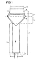
- apparatus (1) comprising inlet end (2), mixer (3) including mixing chamber (4), expander (5), insert (6), diffuser (7) including porous shield (8), and outlet end (9).
- apparatus (1) Upstream of the apparatus (1) are provided respective gaseous fluid conduits (10, 11).
- Gaseous conduits are adapted for the introduction of oxygen-containing gas and combustible gas, such as natural gas.
- the ratio of mixing of respective gaseous fluids may be controlled by known means such as varying of aperture of respective fluid conduits or varying concentration or flow rate of fluids themselves.
- catalyst (12) Downstream of apparatus (1) is illustrated catalyst (12) comprising a monolithic structure mounted in the fluid flow stream in manner to provide uniform fluid-catalyst contacting with diffused fluid having substantially uniform radial velocity profile.
- the gaseous fluids enter the apparatus (1) and are mixed.
- the mixed fluids enter the expander (5) at its upstream end and are equally divided about axially mounted insert (6).
- the annular mixed fluid stream merges by radial inward re-entry about the convex surface of insert (6).
- the diffuser (7) is suitably profiled to provide radial inward momentum component to the mixed fluid stream for the avoidance of flow separation (for example from the wall).
- the diffused mixed fluid stream passes through porous shield (8) and advances for a sufficient distance for the desired conditioning of feed prior to contacting catalyst (12).
- the fluids comprising oxygen and natural gas are pre-heated prior to entering the apparatus (1).
- the reaction is initiated by ignition of feed at the catalyst, whereby gaseous fluids are brought to reaction temperature on approaching the catalyst.
- the mixer (3, 4), expander (5), insert (6) and diffuser (7) are constructed of suitable materials having heat resistance in excess of 400 °C, suitably are constructed of metal alloy and similar compatible materials.
- the catalyst is suitably a catalytically active material as hereinbefore defined supported on a porous monolithic disc-shaped carrier as hereinbefore defined.
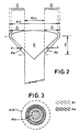
- Figure 2 is shown the expander (5)and insert (6) of Figure 1 wherein the available cross-section area (Aa) is shown, on a section A-A, as being less than the difference in the expander internal cross-sectional area at its downstream and upstream ends respectively (Aid and Aiu respectively).
- Figure 3 is shown the internal and available cross-sectional area (Ai and Aa) on the section A-A through Figure 2, and broken lines show the confines defining Aid and Aiu of Figure 2.
- Methane and oxygen were provided at a pressure in the range of 50 to 60 bara and at a temperature of up to 300 °C to conduits (10) and (11) respectively of the apparatus of Figure 1, were thoroughly mixed. Mixing was at an oxygen-to-carbon ratio of 0.5. The combined feed was supplied at gas hourly space velocity of 2,000,000 Nl/kg/hr.
- Example 1 The process of Example 1 was repeated at atmospheric conditions. The resultant stream was analysed at the outlet end (9).
- the flow velocity and oxygen concentration of the gas leaving the reactor were measured by pitot tube and by univox.
- the velocity profile was substantially uniform within 20%, neglecting surface effects.
- the oxygen partial pressure varied less than 1% over the cross-section.
- Example 1 The process of Example 1 was repeated. Accidental ignition was initiated. Damage due to the explosion that followed ignition was limited to a deformation of the internals. Safe shutdown of the process was achieved.
Landscapes
- Chemical & Material Sciences (AREA)
- Chemical Kinetics & Catalysis (AREA)
- Organic Chemistry (AREA)
- Engineering & Computer Science (AREA)
- Combustion & Propulsion (AREA)
- General Health & Medical Sciences (AREA)
- Health & Medical Sciences (AREA)
- Inorganic Chemistry (AREA)
- Organic Low-Molecular-Weight Compounds And Preparation Thereof (AREA)
- Physical Or Chemical Processes And Apparatus (AREA)
- Feeding And Controlling Fuel (AREA)
- Devices And Processes Conducted In The Presence Of Fluids And Solid Particles (AREA)
- Hydrogen, Water And Hydrids (AREA)
- Detergent Compositions (AREA)
Priority Applications (1)
| Application Number | Priority Date | Filing Date | Title |
|---|---|---|---|
| EP98905287A EP0951345B1 (en) | 1997-01-07 | 1998-01-06 | Fluid mixer and process using the same |
Applications Claiming Priority (4)
| Application Number | Priority Date | Filing Date | Title |
|---|---|---|---|
| EP97200033 | 1997-01-07 | ||
| EP97200033 | 1997-01-07 | ||
| EP98905287A EP0951345B1 (en) | 1997-01-07 | 1998-01-06 | Fluid mixer and process using the same |
| PCT/EP1998/000141 WO1998030322A1 (en) | 1997-01-07 | 1998-01-06 | Fluid mixer and process using the same |
Publications (2)
| Publication Number | Publication Date |
|---|---|
| EP0951345A1 EP0951345A1 (en) | 1999-10-27 |
| EP0951345B1 true EP0951345B1 (en) | 2003-03-26 |
Family
ID=8227915
Family Applications (1)
| Application Number | Title | Priority Date | Filing Date |
|---|---|---|---|
| EP98905287A Expired - Lifetime EP0951345B1 (en) | 1997-01-07 | 1998-01-06 | Fluid mixer and process using the same |
Country Status (12)
| Country | Link |
|---|---|
| US (1) | US6092921A (enExample) |
| EP (1) | EP0951345B1 (enExample) |
| JP (1) | JP4156036B2 (enExample) |
| KR (1) | KR20000069909A (enExample) |
| AU (1) | AU720655B2 (enExample) |
| CA (1) | CA2276464C (enExample) |
| DE (1) | DE69812585T2 (enExample) |
| ID (1) | ID21814A (enExample) |
| NO (1) | NO993339L (enExample) |
| NZ (1) | NZ336399A (enExample) |
| PL (1) | PL334445A1 (enExample) |
| WO (1) | WO1998030322A1 (enExample) |
Families Citing this family (41)
| Publication number | Priority date | Publication date | Assignee | Title |
|---|---|---|---|---|
| US7128278B2 (en) | 1997-10-24 | 2006-10-31 | Microdiffusion, Inc. | System and method for irritating with aerated water |
| US6702949B2 (en) | 1997-10-24 | 2004-03-09 | Microdiffusion, Inc. | Diffuser/emulsifier for aquaculture applications |
| US6386751B1 (en) | 1997-10-24 | 2002-05-14 | Diffusion Dynamics, Inc. | Diffuser/emulsifier |
| US7654728B2 (en) | 1997-10-24 | 2010-02-02 | Revalesio Corporation | System and method for therapeutic application of dissolved oxygen |
| EP0953842A1 (de) * | 1998-05-01 | 1999-11-03 | F. Hoffmann-La Roche Ag | Analysenautomat mit an der Unterseite verjüngter Mischkammer und mit dieser dichtend verbundener Sockeleinheit |
| EP1043271A1 (en) * | 1999-03-30 | 2000-10-11 | Shell Internationale Researchmaatschappij B.V. | Apparatus for the catalytic partial oxidation of hydrocarbons |
| ATE283450T1 (de) | 1999-09-06 | 2004-12-15 | Shell Int Research | Mischvorrichtung |
| AU2001279807A1 (en) | 2000-08-08 | 2002-02-18 | Shell Internationale Research Maatschappij B.V. | Flow distributor |
| DE10049327A1 (de) * | 2000-10-05 | 2002-04-18 | Honeywell Specialty Chemicals | Verfahren und Vorrichtung zur Herstellung von Nickelsulfamat |
| US20070080189A1 (en) * | 2001-06-21 | 2007-04-12 | Jozef Smit Jacobus A | Catalytic reactor |
| US6514316B1 (en) | 2001-08-22 | 2003-02-04 | Mt Systems, Llc | System for improving the maximum operating temperature and lifetime of chromatographic columns |
| WO2003022423A1 (de) * | 2001-09-05 | 2003-03-20 | Webasto Thermosysteme International Gmbh | System zum umsetzen von brennstoff und luft zu reformat und verfahren zur montage eines solchen systems |
| DE10219747B4 (de) * | 2002-05-02 | 2005-06-23 | Daimlerchrysler Ag | Verfahren zur Vermeidung einer Rückzündung in einem einen Reaktionsraum anströmenden Gemisch und Reaktor zur Durchführung des Verfahrens |
| US6783749B2 (en) * | 2002-05-13 | 2004-08-31 | The Boc Group, Inc. | Gas recovery process |
| US7255848B2 (en) * | 2002-10-01 | 2007-08-14 | Regents Of The Univeristy Of Minnesota | Production of hydrogen from alcohols |
| US7262334B2 (en) | 2002-11-13 | 2007-08-28 | Regents Of The University Of Minnesota | Catalytic partial oxidation of hydrocarbons |
| US20040133057A1 (en) * | 2003-01-02 | 2004-07-08 | Conocophillips Company | Gaseous hydrocarbon-oxygen bubble tank mixer |
| US7108838B2 (en) | 2003-10-30 | 2006-09-19 | Conocophillips Company | Feed mixer for a partial oxidation reactor |
| WO2005116168A1 (en) | 2004-05-25 | 2005-12-08 | Regents Of The University Of Minnesota | Production of olefins having a functional group |
| US7416571B2 (en) | 2005-03-09 | 2008-08-26 | Conocophillips Company | Compact mixer for the mixing of gaseous hydrocarbon and gaseous oxidants |
| EP2035128B1 (en) * | 2006-07-03 | 2010-09-01 | Hardi International A/S | An apparatus for dissolving solid particles and liquid substances in a liquid |
| US8445546B2 (en) | 2006-10-25 | 2013-05-21 | Revalesio Corporation | Electrokinetically-altered fluids comprising charge-stabilized gas-containing nanostructures |
| US8784897B2 (en) | 2006-10-25 | 2014-07-22 | Revalesio Corporation | Methods of therapeutic treatment of eyes |
| US8784898B2 (en) | 2006-10-25 | 2014-07-22 | Revalesio Corporation | Methods of wound care and treatment |
| JP5595041B2 (ja) | 2006-10-25 | 2014-09-24 | リバルシオ コーポレイション | 酸素富化溶液を用いる、眼および他のヒト組織の治療処置の方法 |
| US8609148B2 (en) | 2006-10-25 | 2013-12-17 | Revalesio Corporation | Methods of therapeutic treatment of eyes |
| WO2008115290A2 (en) | 2006-10-25 | 2008-09-25 | Revalesio Corporation | Methods of wound care and treatment |
| JP5306214B2 (ja) | 2006-10-25 | 2013-10-02 | リバルシオ コーポレイション | 混合装置 |
| WO2008052361A1 (en) * | 2006-11-03 | 2008-05-08 | Nxtgen Emission Controls Inc. | Fuel processor |
| DE602007009175D1 (de) * | 2006-12-09 | 2010-10-28 | Haldor Topsoe As | Verfahren und Vorrichtung zum Mischen zweier oder mehrerer Fluidströme |
| US9745567B2 (en) | 2008-04-28 | 2017-08-29 | Revalesio Corporation | Compositions and methods for treating multiple sclerosis |
| US9523090B2 (en) | 2007-10-25 | 2016-12-20 | Revalesio Corporation | Compositions and methods for treating inflammation |
| US10125359B2 (en) | 2007-10-25 | 2018-11-13 | Revalesio Corporation | Compositions and methods for treating inflammation |
| CN102076327B (zh) | 2008-05-01 | 2014-04-16 | 利发利希奥公司 | 治疗消化功能紊乱的组合物和方法 |
| US8815292B2 (en) | 2009-04-27 | 2014-08-26 | Revalesio Corporation | Compositions and methods for treating insulin resistance and diabetes mellitus |
| SG10201503600XA (en) | 2010-05-07 | 2015-06-29 | Revalesio Corp | Compositions and methods for enhancing physiological performance and recovery time |
| BR112013003110A2 (pt) | 2010-08-12 | 2016-06-28 | Revalesio Corp | composições e métodos para tratamento de taupatia |
| FR3008626B1 (fr) * | 2013-07-19 | 2015-08-07 | Arkema France | Reacteur pour preparer du cyanure d'hydrogene par le procede d'andrussow, equipement comprenant ledit reacteur et procede utilisant un tel equipement |
| JP6291903B2 (ja) * | 2014-02-26 | 2018-03-14 | 株式会社ジェイテクト | 混練装置 |
| CA2935564A1 (en) * | 2016-07-07 | 2018-01-07 | Nova Chemicals Corporation | Inherently safe oxygen/hydrocarbon gas mixer |
| CN111964052B (zh) * | 2019-05-19 | 2021-11-26 | 宁波方太厨具有限公司 | 一种用于燃气灶的引射管 |
Family Cites Families (11)
| Publication number | Priority date | Publication date | Assignee | Title |
|---|---|---|---|---|
| US2021092A (en) * | 1931-02-09 | 1935-11-12 | Teliet Jean Antoine Marcel | Improved method and means for incorporating a fluid to a stream of a fluid or of a pulverulent solid |
| US3020234A (en) * | 1959-10-06 | 1962-02-06 | Union Carbide Corp | Method and apparatus for producing a homogeneous thermal insulation mixture |
| DE1258835B (de) * | 1964-08-28 | 1968-01-18 | James R Lage Dr | Mischeinrichtung |
| GB1262436A (en) * | 1970-04-03 | 1972-02-02 | Shell Int Research | Apparatus for mixing two gas streams |
| US3702619A (en) * | 1971-01-28 | 1972-11-14 | Shell Oil Co | In-line mixing apparatus for gases |
| US4008580A (en) * | 1974-12-04 | 1977-02-22 | Frigoscandia Contracting, Inc. | Initial quick freeze pan for direct refrigerant contact cooler |
| US4299655A (en) * | 1978-03-13 | 1981-11-10 | Beloit Corporation | Foam generator for papermaking machine |
| JPS60137425A (ja) * | 1983-12-26 | 1985-07-22 | Hitachi Ltd | 流体混合装置 |
| EP0254395B1 (en) * | 1986-05-27 | 1990-11-22 | Imperial Chemical Industries Plc | Method of starting a process for the production of a gas stream containing hydrogen and carbon oxides |
| US5112527A (en) * | 1991-04-02 | 1992-05-12 | Amoco Corporation | Process for converting natural gas to synthesis gas |
| NZ264970A (en) * | 1993-11-29 | 1997-02-24 | Shell Int Research | Hydrocarbon oxidation; catalytic partial oxidation of hydrocarbon feedstock, preparation of carbon monoxide/hydrogen mixture, details regarding catalyst arrangement |
-
1998
- 1998-01-06 AU AU60935/98A patent/AU720655B2/en not_active Ceased
- 1998-01-06 WO PCT/EP1998/000141 patent/WO1998030322A1/en not_active Ceased
- 1998-01-06 NZ NZ336399A patent/NZ336399A/xx unknown
- 1998-01-06 KR KR1019997006121A patent/KR20000069909A/ko not_active Withdrawn
- 1998-01-06 CA CA002276464A patent/CA2276464C/en not_active Expired - Fee Related
- 1998-01-06 PL PL98334445A patent/PL334445A1/xx unknown
- 1998-01-06 EP EP98905287A patent/EP0951345B1/en not_active Expired - Lifetime
- 1998-01-06 DE DE69812585T patent/DE69812585T2/de not_active Expired - Fee Related
- 1998-01-06 ID IDW990651A patent/ID21814A/id unknown
- 1998-01-06 JP JP53056498A patent/JP4156036B2/ja not_active Expired - Fee Related
- 1998-01-07 US US09/004,072 patent/US6092921A/en not_active Expired - Fee Related
-
1999
- 1999-07-06 NO NO993339A patent/NO993339L/no not_active Application Discontinuation
Also Published As
| Publication number | Publication date |
|---|---|
| AU720655B2 (en) | 2000-06-08 |
| JP4156036B2 (ja) | 2008-09-24 |
| PL334445A1 (en) | 2000-02-28 |
| CA2276464A1 (en) | 1998-07-16 |
| NO993339D0 (no) | 1999-07-06 |
| KR20000069909A (ko) | 2000-11-25 |
| CA2276464C (en) | 2007-05-08 |
| DE69812585T2 (de) | 2004-01-08 |
| WO1998030322A1 (en) | 1998-07-16 |
| NO993339L (no) | 1999-09-02 |
| ID21814A (id) | 1999-07-29 |
| JP2001506183A (ja) | 2001-05-15 |
| EP0951345A1 (en) | 1999-10-27 |
| AU6093598A (en) | 1998-08-03 |
| DE69812585D1 (de) | 2003-04-30 |
| NZ336399A (en) | 2000-03-27 |
| US6092921A (en) | 2000-07-25 |
Similar Documents
| Publication | Publication Date | Title |
|---|---|---|
| EP0951345B1 (en) | Fluid mixer and process using the same | |
| CA2383833C (en) | Mixing device | |
| US7931709B2 (en) | Process and apparatus for generating hydrogen | |
| CA1314129C (en) | Gas mixer and distributor for reactor | |
| JPH01145301A (ja) | 炭化水素系原料からの合成ガスの製造 | |
| CN101304804A (zh) | 插入反应器中或与反应器组合的流体混合装置 | |
| KR101353719B1 (ko) | 촉매 반응기 | |
| US6096937A (en) | Process for dehydrogenation of ethylbenzene to styrene | |
| MXPA05008772A (es) | Reactor de cracking auto-termico. | |
| KR19980042067A (ko) | 에틸벤젠을 스티렌으로 탈수소화하기 위한 방법 | |
| EP1307281B1 (en) | Flow distributor | |
| MXPA99006216A (en) | Fluid mixer and process using the same | |
| US7008597B1 (en) | Catalytic reactor | |
| US7491380B2 (en) | Catalytic reactor | |
| CZ241199A3 (cs) | Míchač tekutiny a způsob jeho použití | |
| WO2020092595A1 (en) | Burners for use in producing synthesis gas | |
| RU99117519A (ru) | Устройство для смешения реакционноспособных текучих сред, способ смешения таких сред и способ каталитического парциального окисления углеводородного сырья |
Legal Events
| Date | Code | Title | Description |
|---|---|---|---|
| PUAI | Public reference made under article 153(3) epc to a published international application that has entered the european phase |
Free format text: ORIGINAL CODE: 0009012 |
|
| 17P | Request for examination filed |
Effective date: 19990614 |
|
| AK | Designated contracting states |
Kind code of ref document: A1 Designated state(s): CH DE DK ES FR GB IT LI NL SE |
|
| 17Q | First examination report despatched |
Effective date: 20010611 |
|
| GRAG | Despatch of communication of intention to grant |
Free format text: ORIGINAL CODE: EPIDOS AGRA |
|
| GRAG | Despatch of communication of intention to grant |
Free format text: ORIGINAL CODE: EPIDOS AGRA |
|
| GRAH | Despatch of communication of intention to grant a patent |
Free format text: ORIGINAL CODE: EPIDOS IGRA |
|
| GRAH | Despatch of communication of intention to grant a patent |
Free format text: ORIGINAL CODE: EPIDOS IGRA |
|
| GRAA | (expected) grant |
Free format text: ORIGINAL CODE: 0009210 |
|
| AK | Designated contracting states |
Designated state(s): CH DE DK ES FR GB IT LI NL SE |
|
| PG25 | Lapsed in a contracting state [announced via postgrant information from national office to epo] |
Ref country code: NL Free format text: LAPSE BECAUSE OF FAILURE TO SUBMIT A TRANSLATION OF THE DESCRIPTION OR TO PAY THE FEE WITHIN THE PRESCRIBED TIME-LIMIT Effective date: 20030326 Ref country code: LI Free format text: LAPSE BECAUSE OF FAILURE TO SUBMIT A TRANSLATION OF THE DESCRIPTION OR TO PAY THE FEE WITHIN THE PRESCRIBED TIME-LIMIT Effective date: 20030326 Ref country code: CH Free format text: LAPSE BECAUSE OF FAILURE TO SUBMIT A TRANSLATION OF THE DESCRIPTION OR TO PAY THE FEE WITHIN THE PRESCRIBED TIME-LIMIT Effective date: 20030326 |
|
| REG | Reference to a national code |
Ref country code: GB Ref legal event code: FG4D |
|
| REG | Reference to a national code |
Ref country code: CH Ref legal event code: EP |
|
| REF | Corresponds to: |
Ref document number: 69812585 Country of ref document: DE Date of ref document: 20030430 Kind code of ref document: P |
|
| PG25 | Lapsed in a contracting state [announced via postgrant information from national office to epo] |
Ref country code: SE Free format text: LAPSE BECAUSE OF FAILURE TO SUBMIT A TRANSLATION OF THE DESCRIPTION OR TO PAY THE FEE WITHIN THE PRESCRIBED TIME-LIMIT Effective date: 20030626 Ref country code: DK Free format text: LAPSE BECAUSE OF FAILURE TO SUBMIT A TRANSLATION OF THE DESCRIPTION OR TO PAY THE FEE WITHIN THE PRESCRIBED TIME-LIMIT Effective date: 20030626 |
|
| NLV1 | Nl: lapsed or annulled due to failure to fulfill the requirements of art. 29p and 29m of the patents act | ||
| PG25 | Lapsed in a contracting state [announced via postgrant information from national office to epo] |
Ref country code: ES Free format text: LAPSE BECAUSE OF FAILURE TO SUBMIT A TRANSLATION OF THE DESCRIPTION OR TO PAY THE FEE WITHIN THE PRESCRIBED TIME-LIMIT Effective date: 20030930 |
|
| ET | Fr: translation filed | ||
| REG | Reference to a national code |
Ref country code: CH Ref legal event code: PL |
|
| PLBE | No opposition filed within time limit |
Free format text: ORIGINAL CODE: 0009261 |
|
| STAA | Information on the status of an ep patent application or granted ep patent |
Free format text: STATUS: NO OPPOSITION FILED WITHIN TIME LIMIT |
|
| 26N | No opposition filed |
Effective date: 20031230 |
|
| PG25 | Lapsed in a contracting state [announced via postgrant information from national office to epo] |
Ref country code: IT Free format text: LAPSE BECAUSE OF NON-PAYMENT OF DUE FEES;WARNING: LAPSES OF ITALIAN PATENTS WITH EFFECTIVE DATE BEFORE 2007 MAY HAVE OCCURRED AT ANY TIME BEFORE 2007. THE CORRECT EFFECTIVE DATE MAY BE DIFFERENT FROM THE ONE RECORDED. Effective date: 20050106 |
|
| PGFP | Annual fee paid to national office [announced via postgrant information from national office to epo] |
Ref country code: FR Payment date: 20081120 Year of fee payment: 12 |
|
| PGFP | Annual fee paid to national office [announced via postgrant information from national office to epo] |
Ref country code: DE Payment date: 20090203 Year of fee payment: 12 |
|
| PGFP | Annual fee paid to national office [announced via postgrant information from national office to epo] |
Ref country code: GB Payment date: 20081222 Year of fee payment: 12 |
|
| PGFP | Annual fee paid to national office [announced via postgrant information from national office to epo] |
Ref country code: IT Payment date: 20081209 Year of fee payment: 12 |
|
| PGRI | Patent reinstated in contracting state [announced from national office to epo] |
Ref country code: IT Effective date: 20091201 |
|
| GBPC | Gb: european patent ceased through non-payment of renewal fee |
Effective date: 20100106 |
|
| REG | Reference to a national code |
Ref country code: FR Ref legal event code: ST Effective date: 20100930 |
|
| PG25 | Lapsed in a contracting state [announced via postgrant information from national office to epo] |
Ref country code: FR Free format text: LAPSE BECAUSE OF NON-PAYMENT OF DUE FEES Effective date: 20100201 |
|
| PG25 | Lapsed in a contracting state [announced via postgrant information from national office to epo] |
Ref country code: DE Free format text: LAPSE BECAUSE OF NON-PAYMENT OF DUE FEES Effective date: 20100803 |
|
| PG25 | Lapsed in a contracting state [announced via postgrant information from national office to epo] |
Ref country code: GB Free format text: LAPSE BECAUSE OF NON-PAYMENT OF DUE FEES Effective date: 20100106 |
|
| PG25 | Lapsed in a contracting state [announced via postgrant information from national office to epo] |
Ref country code: IT Free format text: LAPSE BECAUSE OF NON-PAYMENT OF DUE FEES Effective date: 20100106 |