EP0951052A2 - Sprudelvorrichtung und Kondensator dafür - Google Patents
Sprudelvorrichtung und Kondensator dafür Download PDFInfo
- Publication number
- EP0951052A2 EP0951052A2 EP99302180A EP99302180A EP0951052A2 EP 0951052 A2 EP0951052 A2 EP 0951052A2 EP 99302180 A EP99302180 A EP 99302180A EP 99302180 A EP99302180 A EP 99302180A EP 0951052 A2 EP0951052 A2 EP 0951052A2
- Authority
- EP
- European Patent Office
- Prior art keywords
- temperature
- gas mixture
- holding member
- source
- bubbler
- Prior art date
- Legal status (The legal status is an assumption and is not a legal conclusion. Google has not performed a legal analysis and makes no representation as to the accuracy of the status listed.)
- Granted
Links
Images




Classifications
-
- C—CHEMISTRY; METALLURGY
- C23—COATING METALLIC MATERIAL; COATING MATERIAL WITH METALLIC MATERIAL; CHEMICAL SURFACE TREATMENT; DIFFUSION TREATMENT OF METALLIC MATERIAL; COATING BY VACUUM EVAPORATION, BY SPUTTERING, BY ION IMPLANTATION OR BY CHEMICAL VAPOUR DEPOSITION, IN GENERAL; INHIBITING CORROSION OF METALLIC MATERIAL OR INCRUSTATION IN GENERAL
- C23C—COATING METALLIC MATERIAL; COATING MATERIAL WITH METALLIC MATERIAL; SURFACE TREATMENT OF METALLIC MATERIAL BY DIFFUSION INTO THE SURFACE, BY CHEMICAL CONVERSION OR SUBSTITUTION; COATING BY VACUUM EVAPORATION, BY SPUTTERING, BY ION IMPLANTATION OR BY CHEMICAL VAPOUR DEPOSITION, IN GENERAL
- C23C16/00—Chemical coating by decomposition of gaseous compounds, without leaving reaction products of surface material in the coating, i.e. chemical vapour deposition [CVD] processes
- C23C16/44—Chemical coating by decomposition of gaseous compounds, without leaving reaction products of surface material in the coating, i.e. chemical vapour deposition [CVD] processes characterised by the method of coating
- C23C16/448—Chemical coating by decomposition of gaseous compounds, without leaving reaction products of surface material in the coating, i.e. chemical vapour deposition [CVD] processes characterised by the method of coating characterised by the method used for generating reactive gas streams, e.g. by evaporation or sublimation of precursor materials
- C23C16/4487—Chemical coating by decomposition of gaseous compounds, without leaving reaction products of surface material in the coating, i.e. chemical vapour deposition [CVD] processes characterised by the method of coating characterised by the method used for generating reactive gas streams, e.g. by evaporation or sublimation of precursor materials by using a condenser
-
- C—CHEMISTRY; METALLURGY
- C03—GLASS; MINERAL OR SLAG WOOL
- C03B—MANUFACTURE, SHAPING, OR SUPPLEMENTARY PROCESSES
- C03B37/00—Manufacture or treatment of flakes, fibres, or filaments from softened glass, minerals, or slags
- C03B37/01—Manufacture of glass fibres or filaments
- C03B37/012—Manufacture of preforms for drawing fibres or filaments
- C03B37/014—Manufacture of preforms for drawing fibres or filaments made entirely or partially by chemical means, e.g. vapour phase deposition of bulk porous glass either by outside vapour deposition [OVD], or by outside vapour phase oxidation [OVPO] or by vapour axial deposition [VAD]
- C03B37/01413—Reactant delivery systems
-
- C—CHEMISTRY; METALLURGY
- C23—COATING METALLIC MATERIAL; COATING MATERIAL WITH METALLIC MATERIAL; CHEMICAL SURFACE TREATMENT; DIFFUSION TREATMENT OF METALLIC MATERIAL; COATING BY VACUUM EVAPORATION, BY SPUTTERING, BY ION IMPLANTATION OR BY CHEMICAL VAPOUR DEPOSITION, IN GENERAL; INHIBITING CORROSION OF METALLIC MATERIAL OR INCRUSTATION IN GENERAL
- C23C—COATING METALLIC MATERIAL; COATING MATERIAL WITH METALLIC MATERIAL; SURFACE TREATMENT OF METALLIC MATERIAL BY DIFFUSION INTO THE SURFACE, BY CHEMICAL CONVERSION OR SUBSTITUTION; COATING BY VACUUM EVAPORATION, BY SPUTTERING, BY ION IMPLANTATION OR BY CHEMICAL VAPOUR DEPOSITION, IN GENERAL
- C23C16/00—Chemical coating by decomposition of gaseous compounds, without leaving reaction products of surface material in the coating, i.e. chemical vapour deposition [CVD] processes
- C23C16/44—Chemical coating by decomposition of gaseous compounds, without leaving reaction products of surface material in the coating, i.e. chemical vapour deposition [CVD] processes characterised by the method of coating
- C23C16/448—Chemical coating by decomposition of gaseous compounds, without leaving reaction products of surface material in the coating, i.e. chemical vapour deposition [CVD] processes characterised by the method of coating characterised by the method used for generating reactive gas streams, e.g. by evaporation or sublimation of precursor materials
- C23C16/4481—Chemical coating by decomposition of gaseous compounds, without leaving reaction products of surface material in the coating, i.e. chemical vapour deposition [CVD] processes characterised by the method of coating characterised by the method used for generating reactive gas streams, e.g. by evaporation or sublimation of precursor materials by evaporation using carrier gas in contact with the source material
- C23C16/4482—Chemical coating by decomposition of gaseous compounds, without leaving reaction products of surface material in the coating, i.e. chemical vapour deposition [CVD] processes characterised by the method of coating characterised by the method used for generating reactive gas streams, e.g. by evaporation or sublimation of precursor materials by evaporation using carrier gas in contact with the source material by bubbling of carrier gas through liquid source material
Definitions
- This invention relates to a bubbler apparatus which can be employed in apparatuses for manufacturing semiconductors, optical fibers, liquid crystal panels, or the like, and a gas-laser oscillator, for feeding thereto a source contained in a gas mixture in a desired concentration, and a condenser for use with the bubbler apparatus.
- a bubbler apparatus of this kind has been proposed e.g. by Japanese Laid-Open Patent Publication (Kokai) No. 60-248228, which blows a carrier gas controlled at a constant flow rate into a source in a liquid phase (hereinafter referred to as "liquid source”) held in a bubbler vessel to carry out bubbling of the liquid source by using the carrier gas to produce a gas mixture of the carrier gas and the vaporized source.
- liquid source a carrier gas controlled at a constant flow rate into a source in a liquid phase
- the gas mixture thus produced is cooled by a condenser to a desired temperature at which condensation of the vaporized source occurs to thereby form a saturated vapor of the source at the desired temperature, whereby the vaporized source contained in the gas mixture (or the saturated vapor) in a predetermined concentration is fed to a reactor.
- the concentration (at a time point of generation) of the vaporized source in the gas mixture fed to a reactor as well should be maintained constant irrespective of the flow rate of the carrier gas.
- the concentration of the vaporized source is widely varied depending on the shape and hole diameter of a bubbler nozzle or a change in the level of the liquid source in the bubbler vessel.
- the proposed bubbler apparatus is configured such that the condenser is connected to an outlet port of the bubbler vessel to cause the vaporized source in the gas mixture sent from the bubbler vessel to condense at the desired temperature which is slightly lower than the temperature of the vessel.
- the gas mixture flows through a spiral tube arranged within the casing of the condenser, and the temperature of the gas mixture is controlled by causing hot water to circulate through the inside of the casing where the spiral pipe is arranged.
- This arrangement of the condenser cannot provide control of the temperature of the gas mixture in quick response to a change in the temperature thereof, and also makes it difficult to detect the true or approximately true temperature of the gas mixture flowing through the spiral tube. For this reason, the condenser cannot be maintained at a desired temperature, inevitably causing a variation in concentration of the vaporized source.
- feed rate represented by "the flow rate of the carrier gas x the concentration of the source in the gas mixture x K, wherein K is a constant, which is set to a value of about 1 in the case of a solid source, such as TMI (trimethyl indium), and in a range of 1 to 2, in the case of a liquid source").
- a bubbler apparatus including a bubbler vessel holding a source and having a carrier gas blown therein at a controlled flow rate to provide a gas mixture of the carrier gas and the source by bubbling, and a condenser for cooling the gas mixture to a desired temperature at which condensation of the source occurs to provide a saturated vapor of the source at the desired temperature, the source contained in the gas mixture in a desired concentration as the saturated vapor being fed to a reactor block.
- the bubbler apparatus according to a first aspect of the invention is characterized in that the condenser comprises:
- the gas mixture sent from the bubbler vessel is mixed as it flows through the static mixer, to thereby achieve a uniform temperature distribution of the gas mixture.
- the temperature of the gas mixture is transmitted to the holding member made of a material having a high thermal conductivity. This makes the temperature of the holding member approximately equal to a true temperature of the gas mixture in the static mixer.
- the temperature sensor When the temperature of the holding member is detected by the temperature sensor, it is possible to detect a temperature close to the true temperature of the gas mixture in the static mixer. Therefore, by controlling the temperature adjust means such that the temperature value detected by the temperature sensor becomes equal to a desired temperature, it is possible to cause the source in the gas mixture flowing in the static mixer to always condense at the predetermined temperature. This makes it possible to always feed the source contained in the gas mixture in a fixed concentration from the condenser to the reactor block.
- the temperature adjust means comprises at least one of heating means for heating the holding member and cooling means for cooling the holding member.
- the static mixer includes a pipe defining a passage through which flows the gas mixture supplied from the bubbler vessel, and at least one pair of mixing elements for mixing and stirring the gas mixture flowing through the pipe in a manner such that part of the gas mixture at a peripheral portion of the passage and part of the gas mixture at a central portion of the passage are replaced with each other.
- the mixing elements of the static mixer are made of a material having a high thermal conductivity.
- the heat of the gas mixture flowing through the pipe is transmitted to the holding member via the mixing elements made of the material having a high thermal conductivity, whereby the temperature of the holding member detected by the temperature sensor is made closer to the true temperature of the gas mixture, so that it becomes possible to control the temperature of the condenser with higher accuracy based on the thus detected temperature closer to the true temperature of the gas mixture.
- the source in the gas mixture can be caused to constantly condense at the predetermined temperature.
- the pipe of the static mixer and the holding member are made of a material having a high thermal conductivity in a manner such that the pipe and the holding member form a unitary flow path-forming member, the flow path-forming member defining a through hole therein through which the gas mixture flows and which is provided with the at least one pair of mixing elements therein, the temperature sensor detecting a temperature of the flow path-forming member.
- the heat of the gas mixture flowing in the through hole of the flow path-forming member is directly transmitted to the flow path-forming member made of a material having a high thermal conductivity, and at the same time the temperature of the flow path-forming member is detected by the temperature sensor.
- the temperature detected by the temperature sensor is made closer to the true temperature of the gas mixture, so that it becomes possible to control the temperature of the condenser with higher accuracy based on the thus detected temperature closer to the true temperature of the gas mixture.
- the source in the gas mixture is caused to constantly condense at the predetermined temperature.
- the cooling means comprises thermoelectric conversion elements arranged in a manner such that the thermoelectric conversion elements each have a heat absorption surface thereof in contact with an outer surface of the holding member, for cooling the holding member, and auxiliary cooling means for cooling a heat dissipation surface of each of the thermoelectric conversion elements.
- the holding member is cooled by the heat absorption surface of each thermoelectric conversion element, while the heat dissipation surface of each thermoelectric conversion element is cooled by the auxiliary cooling means, which makes it possible to efficiently cool the condenser to the desired temperature. This makes it possible to preserve the desired temperature of the gas mixture in quick response to a change in the detected temperature of the condenser.
- a condenser for use in cooling a gas mixture of a carrier gas and a source supplied from a bubbler vessel of a bubbler apparatus to a desired temperature at which condensation of the source occurs to thereby provide a saturated vapor of the source at the predetermined temperature.
- the condenser according to the second aspect of the invention is characterized by comprising:
- the gas mixture sent from the bubbler vessel is mixed in the static mixer, to thereby cause the gas mixture to have a uniform temperature distribution.
- the heat of this mixture is transmitted to the holding member made of a material having a high thermal conductivity. This makes the temperature value of the holding member detected by the temperature sensor approximately equal to the true temperature of the gas mixture in the static mixer.
- This enable the condenser to be kept at the predetermined temperature by controlling at least one of the heating means and the cooling means based on the temperature value detected by the temperature sensor, and what is more, the temperature control can be carried out more efficiently with higher accuracy.
- the bubbler apparatus is used with a semiconductor-manufacturing apparatus to feed a deposition source material thereto.
- the bubbler apparatus can be employed not only in the semiconductor-manufacturing apparatus but also in an apparatus for manufacturing optical fibers or liquid crystal panels, or a gas-laser oscillator that is required to be stably supplied with a gas mixture containing a source in a predetermined concentration.
- the bubbler apparatus blows a carrier gas controlled by a mass flow controller 1 at a constant flow rate into a source 3 in a liquid phase held in a bubbler vessel (bubbler bottle) 2 to thereby carry out bubbling of the liquid source 3 by using the carrier gas to produce a gas mixture of the carrier gas and the vaporized source 3.
- the gas mixture is cooled by a condenser 4 to a desired temperature (e.g. 40 °C) at which condensation of the source 3 occurs to provide a saturated vapor of the source at the desired temperature, and the saturated vapor is fed to a reactor 5.
- the bubbler vessel 2 is heated by a heater 6 such that the gas mixture is maintained at a predetermined temperature (e.g. 50 °C).
- the condenser 4 includes a static mixer 9 having a pipe 8 (see FIG. 7) connected to a mixture outlet side of the bubbler vessel 2, for mixing the gas mixture sent from the bubbler vessel 2 in the mixer pipe 8, a holding member 10 made of a material having a high thermal conductivity and enclosing the whole periphery of the pipe 8 of the static mixer 9, and a temperature sensor 11 for detecting a temperature of the holding member 10.
- the condenser 4 includes heaters 12 for heating the holding member 10, and thermoelectric conversion elements 13 for cooling the holding member 10.
- the condenser 4 is configured such that a condenser control unit 14 (see FIG. 2) controls the heaters 12 and the thermoelectric conversion elements 13 in response to an output (detection value) from the temperature sensor 11, to maintain the temperature of the gas mixture flowing through the mixer pipe 8 at a desired temperature (e.g. 40 °C).
- the pipe 8 of the static mixer 9 is connected to the mixture outlet side of the bubbler vessel 2 such that the vaporized source 3 having condensed to a liquid in the mixer pipe 8 can drop into the bubbler vessel 2 or flow down an inner wall of the mixer pipe 8 to return to the bubbler vessel 2. More specifically, the mixer pipe 8 is connected to a pipe 15 in a manner extending upward from the pipe 15.
- the pipe 15 has a lower end thereof arranged in an upper space 7 of the bubbler vessel 2 and extends upward to have an upper end thereof connected to the mixer pipe 8 (see FIG. 2).
- the mixer pipe 8 has pipe fittings 16, 17 provided at opposite ends thereof (see FIG. 7).
- the static mixer 9 has mixing elements 19 for mixing and stirring the gas mixture flowing through the mixer pipe 8 in a manner such that part of the gas mixture at a peripheral portion of a passage defined within the pipe 8 and part of the gas mixture at a central portion of the same are replaced with each other.
- three pairs of mixing elements 19 are arranged in the mixer pipe 8.
- Each mixing element 19 is comprised of a first guide plate group 20 for guiding part of the gas mixture flowing at the peripheral portion of the passage of the pipe 8 to the central portion of the same and a second guide plate group 21 for guiding part of the gas mixture flowing at the central portion of the passage within the pipe 8 to the peripheral portion of the same.
- Each of the guide plate groups 20, 21 is comprised of three triangular guide plates.
- Static Mixer for instance, disclosed in Japanese Patent No. 1942734 (Japanese Patent Publication (Kokoku) No. 6-071542) owned by the present applicant and incorporated herein by reference is used as the above static mixer 9.
- the above patented static mixer is employed as the static mixer 9, this is not limitative, but any static mixer may be used so long as it is capable of mixing and stirring a gas mixture flowing through the mixer pipe 8 in a manner such that part of the gas mixture flowing at a peripheral portion of a passage within the pipe 8 and part of the gas mixture flowing at a central portion of the same are replaced with each other, thereby attaining the uniform temperature distribution of the gas mixture.
- the mixer pipe 8 is made of a corrosion-resistant material, such as stainless steel or the like.
- the pipe fitting 16 on the mixture inlet side of the static mixer 9 has an internal diameter which is large enough to cause the source having condensed in the mixer pipe 8 and dropping down in the mixer pipe 8 to positively return to the bubbler vessel 2 and at the same time not to hinder the gas mixture from entering the mixer pipe 8. More specifically, the internal diameter of the pipe fitting 16 on the mixture inlet side of the mixer pipe 8 is made sufficiently large so as to prevent the condensed liquid source from joining to the liquid source adhering to the inner wall of the pipe fitting 16 and blocking the passage of the gas mixture to stop the flow of the gas mixture into the static mixer 9.
- the pipe fitting 17 on the saturated vapor outlet side of the mixer pipe 8 is only required to have an internal diameter large enough not to hinder the flow of the saturated vapor and hence made smaller than that of the pipe fitting 16 on the mixture inlet side.
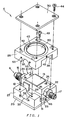
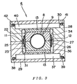
- the holding member 10 is comprised of a pair of holding. bodies 22, 23, as shown in FIGS. 1 and 3.
- Each of the holding bodies 22, 23 is in the form of a rectangular parallelepiped provided with a concave portion which has a semicylindrical shape and is in contact with an outer surface of the mixer pipe 8.
- each of the holding bodies 22, 23 is made of a material having a high thermal conductivity, such as a metal material, e.g., copper and silver, or a ceramic material, e.g. beryllia ceramics, or the like.
- the temperature sensor 11 is fixed to an outer surface of the holding member 10 by a retainer 25. An output signal from the temperature sensor 11 is delivered to the condenser control unit 14. Although in the present embodiment, the temperature sensor 11 is fixed to the outer surface of the holding member 10, this is not limitative, but the temperature sensor 11 may be embedded in the inside of the holding member 10. In such a case, it is possible to detect a temperature closer to the true temperature of the gas mixture flowing through the mixer pipe 8 of the static mixer 9.
- the heaters 12 are fixed to respective side walls of the holding member 10 at such locations that they extend across boundaries of the holding bodies 22, 23.
- the heating operation of each heater 12 is controlled by a heater control block, not shown, provided with the control unit 14. Further, such a heater 12 may be provided only on one side wall of the holding member 10.
- thermoelectric conversion elements 13 are each comprised of a combination of an n-type and a p-type semiconductor elements and operate to absorb heat at a rate dependent on electric current passing therethrough by the Peltier effect.
- the elements 13 are rigidly mounted on the top and bottom surfaces (surfaces without the heaters 12 provided thereon) of the holding member 10, as viewed in FIG. 3, respectively, with heat absorption-side surfaces (heat absorption surfaces) thereof in contact with the holding member 10, whereby the holding member 10 is cooled by the elements 13.
- a surface of each thermoelectric conversion element 13 (heat dissipation surface) opposite to the heat absorption surface is also heated by heat absorbed, and to dissipate the heat, this heat dissipation surface is cooled by water-cooling, as described hereinafter.
- thermoelectric conversion element 13 has a heat absorption amount thereof controlled by a thermoelectric conversion element control block, not shown, provided within the control unit 14. Further, the thermoelectric conversion element 13 of the above-mentioned kind may be provided only on one of the top and bottom surfaces of the holding member 10, as viewed in FIG. 3.
- the condenser 4 includes a pair of casings 27, 28 enclosing the whole periphery of the holding member 10 and a pair of lids 29, 30.
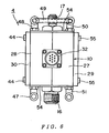
- the casing 27, one of the above casings is formed with a receiving groove 31 having a shape rectangular in cross-section and receiving the whole of one (23 in the illustrated example) of the pair of holding bodies 22, 23, and a concave portion 33 having a semi-cylindrical shape in cross section for receiving therein a hollow cylindrical portion, not shown, of a connector 32, shown in FIG. 6.
- the holding body 23 is received in the receiving groove 31 of the casing 27 in a stable manner.
- the other casing 28 is formed with a receiving groove 34 having a shape rectangular in cross-section and receiving the whole of the other holding body 22, and a concave portion 35 having a semi-cylindrical shape in cross section for receiving therein the hollow cylindrical portion of the connector 32. Further, a gap between the receiving groove 31 of the casing 27 and the holding body 23 and a gap between the receiving groove 34 of the casing 28 and the holding body 22 are filled with thermal insulators.
- the casing 27 is formed with a water-receiving space 37 having a circular shape and arranged adjacent to the inside of the receiving groove 31 via a thin wall, and an annular groove 39 in which an O-ring 38 is fitted for water-tightly sealing between the casing 27 and the lid 29.
- the casing 28 is formed with a water-receiving space 40 having a circular shape and arranged adjacent to the inside of the receiving groove 34 via a thin wall, and an annular groove 42 in which an O-ring 41 is fitted for water-tightly sealing between the casing 28 and the lid 30.
- the casings 27, 28 are secured to each other at four locations by using bolts 43. Further, the lid 30 is fixed to the casing 28 at four locations by using bolts 44. Similarly, the lid 29 is fixed to the casing 27 at four locations by using bolts 55 (see FIG. 6).
- the casing 28 has two through holes 45 formed through portions thereof opposite to each other, for communicating the water-receiving space 40 with the outside of the casing, while the casing 27 has two through holes 46 formed through portions thereof opposite to each other, for communicating the water-receiving space 37 with the outside of the casing 27.
- One of the two through holes 45 of the casing 28 has a cooling water tube fitting 47 attached thereto for guiding cooling water (tap water) into the water-receiving space 40, while the other through hole 45 has a cooling water pipe fitting 48 attached thereto (see FIGS. 4 to 6).
- one of the two through holes 46 of the casing 27 has a cooling water pipe fitting 50 connected to the water-receiving space 40 via the cooling water pipe fitting 48 and a tube 49, while the other through hole 46 has a cooling water pipe fitting 51 attached thereto for discharging cooling water from the water-receiving space 37 to the outside of the casing.
- cooling water which has entered the water-receiving space 40 via the cooling water tube fitting 47 is guided to the water-receiving space 37 via the pipe fitting 48, the tube 49 and the pipe fitting 50, and thereafter discharged from the water-receiving space 37 to the outside by way of the pipe fitting 51.
- Water-cooling means (auxiliary cooling means) constructed as described above cools the heat dissipation surface of the thermoelectric conversion element 13 by using cooling water.
- water-cooling means may be replaced by auxiliary cooling means of a forced-air cooling type which cools the heat dissipation surface by using a fan, auxiliary cooling means of a natural-air cooling type which cools the heat dissipation surface by a cooling plate for spontaneous heat dissipation, or auxiliary cooling means using a heat pipe.
- Reference numerals 52, 53 in FIG. 1 designate screw holes for rigidly mounting the connector 32 on the casings 27, 28 by using four screws (see Fig. 6).
- reference numeral 54 designates thermal insulators for filling two openings formed between the holding member 10 and the casing 27, 28 on the opposite sides of the holding member 10
- reference numeral 56 in FIG. 2 designates a tape heater for heating the pipe 18 so as to prevent recondensation of the saturated vapor before the saturated vapor reaches the reactor 5.
- the carrier gas controlled by the mass flow controller 1 at a constant flow rate is blown into the liquid source 3 contained in the bubbler vessel 2 to carry out bubbling of the liquid source 3 by using the carrier gas
- a mixture of the carrier gas and the vaporized liquid source 3 as a source gas fills the upper space 7 of the bubbler vessel 2 and is sent to the condenser 4 through the pipe 15.
- the gas mixture sent from the bubbler vessel 2 to the condenser 4 is preheated by the heater 6 to a predetermined temperature, for instance, to 50 °C.
- the gas mixture is guided into the pipe 8 of the static mixer 9 in the condenser 4 and mixed by the three pairs of mixing elements 19 as it flows through the mixer pipe 8, such that part of the gas mixture at a peripheral portion of the passage within the mixer pipe 8 and part of the gas mixture at a central portion of the same are replaced with each other, whereby the gas mixture is caused to have a uniform temperature distribution.
- the heat of the gas mixture is transmitted to the holding member 10 made of the metal material having a high thermal conductivity.
- the temperature of the holding member 10 approximately equal to a true temperature of the gas mixture in the mixer pipe 8, and hence by detecting the temperature of the holding member 10 by the temperature sensor 11, it is possible to detect a temperature value close to the true temperature of the gas mixture in the mixer pipe 8.
- the heaters 12 and the thermoelectric conversion elements 13 are controlled by the control unit 14 such that the temperature detected by the temperature sensor 11 becomes equal to a desired temperature, e.g. 40 °C, which enables the vaporized source in the gas mixture flowing in the mixer pipe 8 to constantly condense at a fixed and desired temperature.
- the relationship between a temperature at which the vaporized source in the gas mixture is caused to condense by the condenser 4 and a concentration in which the vaporized source is contained in the gas mixture when the condensation is effected by the condenser 4 is determined in advance by using a real-time gas concentration meter, so long as only the temperature at which the vaporized source in the gas mixture condenses is kept constant, the vaporized source, i.e. deposition source material is always supplied in a fixed concentration, even if the flow rate of the carrier gas is varied.
- the flow rate of the carrier gas and the feed rate of the source come to have a linear relationship or proportionality (in the case of a solid source, the aforementioned constant K as a proportionality constant is approximately equal to 1). Therefore, to increase the amount of the source material to be deposited (e.g. thickness of the deposition) by two times, it is only required e.g. in the case of a solid source that the flow rate of the carrier gas is increased by two times, so that it is possible to easily control the amount of the deposition source material taken out of the bubbler apparatus to the reactor per unit time.
- the pipe 8 of the static mixer 9 is straight and connected to the pipe 15 in a manner continuing upward from the pipe 15.
- the internal diameter of the pipe fitting 16 on the mixture inlet side of the pipe 8 is made sufficiently large so as to prevent the condensed liquid source from joining to the liquid source adhering to the inner wall of the pipe fitting 16 and closing the pipe hole as the passage of the gas mixture to block off the mixture flowing therein, so that the liquid source condensed from the vaporized source and dropping in the mixer pipe 8 is caused to positively return to the bubbler vessel 2 without blocking the gas mixture from entering the mixer pipe 8.
- the condensed liquid source is prevented from filling the pipe 8, which makes it possible to dispense with a countermeasure against the blocked pipe 8 as well as obtain saturated vapor of the source in a stable state.
- the cooling means for cooling the holding member 10 is comprised of the thermoelectric conversion elements 13 each having a heat absorption surface in contact with the outer surface of the holding member 10 for cooling the same, and the water-cooling means (auxiliary cooling means) for cooling the heat dissipation surface of each thermoelectric conversion element 13. Therefore, the holding member 10 is cooled by the heat absorption surface of each thermoelectric conversion element 13, while the heat dissipation surface of each thermoelectric conversion element 13 is cooled by the water-cooling means, which makes it possible to efficiently cool the condenser 4 to a desired temperature, whereby the cooling means can preserve the desired temperature of the condenser in a manner highly responsive to a change therein.
- the mixing elements 19 of the static mixer 9 are made of the above-mentioned material having a high thermal conductivity, whereby the temperature of the holding member 10 detected by the temperature sensor 11 is made closer to the true temperature of the gas mixture, enabling control of the temperature of the condenser 4 with higher accuracy in response to the detected temperature closer to the true temperature of the gas mixture. This makes it possible for the condenser 4 to cause the vaporized source in the gas mixture to constantly condense at a predetermined temperature.
- liquid source not only the liquid source but also a solid source, such as TMI (trimethyl indium), can be used.
- TMI trimethyl indium
- the pipe 8 of the static mixer 9 and the holding member 10 may be made of a material having a high thermal conductivity such that they form a unitary flow path-forming member defining therein a through hole for the gas mixture to flow therethrough, whereby a temperature of the flow path-forming member may be detected by the temperature sensor 11.
- the condenser 4 By configuring the condenser 4 as described above, the heat of the gas mixture flowing through the through hole of the flow path-forming member is directly transmitted to the flow path-forming member made of the material having a high thermal conductivity, and at the same time the temperature of the flow path-forming member is detected by the temperature sensor 11.
- the temperature detected by the temperature sensor 11 is made closer to the true temperature of the gas mixture, so that it becomes possible to control the temperature of the condenser 4 with higher accuracy based on the thus detected temperature closer to the true temperature of the gas mixture.
- This makes it possible for the condenser 4 to cause the vaporized source in the gas mixture to constantly condense at a predetermined temperature.
- the bubbler apparatus according to the present embodiment can be applied to a gas-laser oscillator, to thereby stably feed a source contained in a gas mixture in a predetermined concentration to the gas-laser oscillator.
- the gas-laser oscillator itself corresponds to the reactor 5, described above, to serve as a reactor block to which is fed the vaporized source in the gas mixture in a predetermined concentration.
- the bubbler apparatus of the invention it is possible to feed the source to the reactor block in a fixed concentration in the gas mixture to thereby maintain a constant rate of feed thereof to the reactor block.
- the condenser for use with the bubbler apparatus of the invention, it is possible to always maintain its temperature at a predetermined temperature, thereby permitting the vaporized source in the mixture to condense at a fixed temperature.
Landscapes
- Chemical & Material Sciences (AREA)
- Engineering & Computer Science (AREA)
- General Chemical & Material Sciences (AREA)
- Chemical Kinetics & Catalysis (AREA)
- Materials Engineering (AREA)
- Organic Chemistry (AREA)
- Metallurgy (AREA)
- Mechanical Engineering (AREA)
- Life Sciences & Earth Sciences (AREA)
- General Life Sciences & Earth Sciences (AREA)
- Geochemistry & Mineralogy (AREA)
- Manufacturing & Machinery (AREA)
- Feeding, Discharge, Calcimining, Fusing, And Gas-Generation Devices (AREA)
- Vaporization, Distillation, Condensation, Sublimation, And Cold Traps (AREA)
- Crystals, And After-Treatments Of Crystals (AREA)
Applications Claiming Priority (2)
| Application Number | Priority Date | Filing Date | Title |
|---|---|---|---|
| JP8135398 | 1998-03-27 | ||
| JP10081353A JP2969101B2 (ja) | 1998-03-27 | 1998-03-27 | バブリング装置に用いるコンデンサ |
Publications (3)
| Publication Number | Publication Date |
|---|---|
| EP0951052A2 true EP0951052A2 (de) | 1999-10-20 |
| EP0951052A3 EP0951052A3 (de) | 2003-03-05 |
| EP0951052B1 EP0951052B1 (de) | 2004-12-15 |
Family
ID=13744005
Family Applications (1)
| Application Number | Title | Priority Date | Filing Date |
|---|---|---|---|
| EP19990302180 Expired - Lifetime EP0951052B1 (de) | 1998-03-27 | 1999-03-22 | Sprudelvorrichtung und Kondensator dafür |
Country Status (3)
| Country | Link |
|---|---|
| EP (1) | EP0951052B1 (de) |
| JP (1) | JP2969101B2 (de) |
| DE (1) | DE69922573T2 (de) |
Cited By (2)
| Publication number | Priority date | Publication date | Assignee | Title |
|---|---|---|---|---|
| WO2007138439A1 (en) * | 2006-06-01 | 2007-12-06 | L'air Liquide-Societe Anonyme Pour L'etude Et L'exploitation Des Procedes Georges Claude | System and method for delivery of precursor material |
| US20220274071A1 (en) * | 2019-07-23 | 2022-09-01 | Nanomist Technologies Co., Ltd. | Dissolution method |
Family Cites Families (3)
| Publication number | Priority date | Publication date | Assignee | Title |
|---|---|---|---|---|
| JPS60248228A (ja) * | 1984-05-24 | 1985-12-07 | Sumitomo Electric Ind Ltd | バブリング装置 |
| JPH085690B2 (ja) * | 1987-01-14 | 1996-01-24 | 住友電気工業株式会社 | 原料供給方法および装置 |
| JPH0671542B2 (ja) * | 1991-04-24 | 1994-09-14 | アプリオリ株式会社 | 流体の静止型混合器 |
-
1998
- 1998-03-27 JP JP10081353A patent/JP2969101B2/ja not_active Expired - Lifetime
-
1999
- 1999-03-22 EP EP19990302180 patent/EP0951052B1/de not_active Expired - Lifetime
- 1999-03-22 DE DE69922573T patent/DE69922573T2/de not_active Expired - Lifetime
Cited By (4)
| Publication number | Priority date | Publication date | Assignee | Title |
|---|---|---|---|---|
| WO2007138439A1 (en) * | 2006-06-01 | 2007-12-06 | L'air Liquide-Societe Anonyme Pour L'etude Et L'exploitation Des Procedes Georges Claude | System and method for delivery of precursor material |
| FR2901713A1 (fr) * | 2006-06-01 | 2007-12-07 | Air Liquide | Procede de distribution de produits precurseurs, notamment pyrophoriques |
| US20220274071A1 (en) * | 2019-07-23 | 2022-09-01 | Nanomist Technologies Co., Ltd. | Dissolution method |
| US11806679B2 (en) * | 2019-07-23 | 2023-11-07 | Nanomist Technologies Co., Ltd. | Dissolution method |
Also Published As
| Publication number | Publication date |
|---|---|
| JPH11276880A (ja) | 1999-10-12 |
| DE69922573D1 (de) | 2005-01-20 |
| JP2969101B2 (ja) | 1999-11-02 |
| EP0951052B1 (de) | 2004-12-15 |
| EP0951052A3 (de) | 2003-03-05 |
| DE69922573T2 (de) | 2005-12-08 |
Similar Documents
| Publication | Publication Date | Title |
|---|---|---|
| TWI870434B (zh) | 溫度控制系統、化學品輸送系統、及將一化學品輸送至一反應室之方法 | |
| US6874770B2 (en) | High flow rate bubbler system and method | |
| US7201942B2 (en) | Coating method | |
| JP2789458B2 (ja) | 液体気化のための流量制御装置 | |
| US6214121B1 (en) | Pedestal with a thermally controlled platen | |
| US5183510A (en) | Apparatus and process for chemical vapor deposition | |
| KR100392712B1 (ko) | 화학처리 반응기의 정량 증기공급 시스템 | |
| JP4393677B2 (ja) | 液体材料気化方法および装置並びに制御バルブ | |
| KR101152715B1 (ko) | 증기 이송 장치, 기화기, 기화기 유닛 및 기화된 소스 물질 이송 방법 | |
| US7569191B2 (en) | Method and apparatus for providing precursor gas to a processing chamber | |
| TWI482875B (zh) | 固定濃度蒸發之方法及使用該方法之裝置 | |
| US11390951B2 (en) | Fluid control device | |
| US20160002788A1 (en) | Chemical vapour deposition device | |
| US4667730A (en) | Temperature regulating apparatus for a laboratory reaction vessel arrangement | |
| US20070194470A1 (en) | Direct liquid injector device | |
| US10066295B2 (en) | Source container and vapour-deposition reactor | |
| KR20000069866A (ko) | 플래시 기화기 | |
| US11976356B2 (en) | Vaporized feed device | |
| EP0951052B1 (de) | Sprudelvorrichtung und Kondensator dafür | |
| JP4490160B2 (ja) | 有機薄膜の成膜装置 | |
| US5731508A (en) | Calibrating gas generator | |
| KR20140094657A (ko) | 액체재료 기화장치 | |
| US9914997B2 (en) | Method for supplying a process with an enriched carrier gas | |
| US1176212A (en) | Valve. | |
| KR100322411B1 (ko) | 액체원료 기화장치 |
Legal Events
| Date | Code | Title | Description |
|---|---|---|---|
| PUAI | Public reference made under article 153(3) epc to a published international application that has entered the european phase |
Free format text: ORIGINAL CODE: 0009012 |
|
| AK | Designated contracting states |
Kind code of ref document: A2 Designated state(s): AT BE CH CY DE DK ES FI FR GB GR IE IT LI LU MC NL PT SE |
|
| AX | Request for extension of the european patent |
Free format text: AL;LT;LV;MK;RO;SI |
|
| PUAL | Search report despatched |
Free format text: ORIGINAL CODE: 0009013 |
|
| AK | Designated contracting states |
Kind code of ref document: A3 Designated state(s): AT BE CH CY DE DK ES FI FR GB GR IE IT LI LU MC NL PT SE |
|
| AX | Request for extension of the european patent |
Extension state: AL LT LV MK RO SI |
|
| 17P | Request for examination filed |
Effective date: 20030714 |
|
| 17Q | First examination report despatched |
Effective date: 20030929 |
|
| AKX | Designation fees paid |
Designated state(s): CH DE FR GB LI |
|
| GRAP | Despatch of communication of intention to grant a patent |
Free format text: ORIGINAL CODE: EPIDOSNIGR1 |
|
| GRAS | Grant fee paid |
Free format text: ORIGINAL CODE: EPIDOSNIGR3 |
|
| GRAA | (expected) grant |
Free format text: ORIGINAL CODE: 0009210 |
|
| AK | Designated contracting states |
Kind code of ref document: B1 Designated state(s): CH DE FR GB LI |
|
| REG | Reference to a national code |
Ref country code: GB Ref legal event code: FG4D Ref country code: CH Ref legal event code: EP |
|
| REG | Reference to a national code |
Ref country code: IE Ref legal event code: FG4D |
|
| REF | Corresponds to: |
Ref document number: 69922573 Country of ref document: DE Date of ref document: 20050120 Kind code of ref document: P |
|
| REG | Reference to a national code |
Ref country code: CH Ref legal event code: NV Representative=s name: CABINET GERMAIN & MAUREAU |
|
| PLBE | No opposition filed within time limit |
Free format text: ORIGINAL CODE: 0009261 |
|
| STAA | Information on the status of an ep patent application or granted ep patent |
Free format text: STATUS: NO OPPOSITION FILED WITHIN TIME LIMIT |
|
| 26N | No opposition filed |
Effective date: 20050916 |
|
| ET | Fr: translation filed | ||
| REG | Reference to a national code |
Ref country code: CH Ref legal event code: PUE Owner name: APRIORI CORPORATION Free format text: KOMIYA, KOSHO#2-12 TSUKUSHINO 1-CHOME#ABIKO-SHI, CHIBA-KEN (JP) -TRANSFER TO- APRIORI CORPORATION#KANDA CENTRAL BUILDING 1-7, KANDA-SUDACHO, CHIYODA-KU#TOKYO 101-0041 (JP) |
|
| REG | Reference to a national code |
Ref country code: GB Ref legal event code: 732E Free format text: REGISTERED BETWEEN 20100218 AND 20100224 |
|
| PGFP | Annual fee paid to national office [announced via postgrant information from national office to epo] |
Ref country code: CH Payment date: 20100325 Year of fee payment: 12 |
|
| REG | Reference to a national code |
Ref country code: FR Ref legal event code: TP |
|
| PGFP | Annual fee paid to national office [announced via postgrant information from national office to epo] |
Ref country code: FR Payment date: 20100402 Year of fee payment: 12 |
|
| PGFP | Annual fee paid to national office [announced via postgrant information from national office to epo] |
Ref country code: GB Payment date: 20100218 Year of fee payment: 12 |
|
| PGFP | Annual fee paid to national office [announced via postgrant information from national office to epo] |
Ref country code: DE Payment date: 20100419 Year of fee payment: 12 |
|
| REG | Reference to a national code |
Ref country code: CH Ref legal event code: PFA Owner name: APRIORI CORPORATION Free format text: APRIORI CORPORATION#KANDA CENTRAL BUILDING 1-7, KANDA-SUDACHO, CHIYODA-KU#TOKYO 101-0041 (JP) -TRANSFER TO- APRIORI CORPORATION#KANDA CENTRAL BUILDING 1-7, KANDA-SUDACHO, CHIYODA-KU#TOKYO 101-0041 (JP) |
|
| REG | Reference to a national code |
Ref country code: CH Ref legal event code: PL |
|
| GBPC | Gb: european patent ceased through non-payment of renewal fee |
Effective date: 20110322 |
|
| REG | Reference to a national code |
Ref country code: FR Ref legal event code: ST Effective date: 20111130 |
|
| PG25 | Lapsed in a contracting state [announced via postgrant information from national office to epo] |
Ref country code: DE Free format text: LAPSE BECAUSE OF NON-PAYMENT OF DUE FEES Effective date: 20111001 Ref country code: FR Free format text: LAPSE BECAUSE OF NON-PAYMENT OF DUE FEES Effective date: 20110331 Ref country code: CH Free format text: LAPSE BECAUSE OF NON-PAYMENT OF DUE FEES Effective date: 20110331 Ref country code: LI Free format text: LAPSE BECAUSE OF NON-PAYMENT OF DUE FEES Effective date: 20110331 |
|
| REG | Reference to a national code |
Ref country code: DE Ref legal event code: R119 Ref document number: 69922573 Country of ref document: DE Effective date: 20111001 |
|
| PG25 | Lapsed in a contracting state [announced via postgrant information from national office to epo] |
Ref country code: GB Free format text: LAPSE BECAUSE OF NON-PAYMENT OF DUE FEES Effective date: 20110322 |