EP0950503B1 - Verfahren zur Herstellung von thermoplastischen Hohlkörpern - Google Patents
Verfahren zur Herstellung von thermoplastischen Hohlkörpern Download PDFInfo
- Publication number
- EP0950503B1 EP0950503B1 EP19980105637 EP98105637A EP0950503B1 EP 0950503 B1 EP0950503 B1 EP 0950503B1 EP 19980105637 EP19980105637 EP 19980105637 EP 98105637 A EP98105637 A EP 98105637A EP 0950503 B1 EP0950503 B1 EP 0950503B1
- Authority
- EP
- European Patent Office
- Prior art keywords
- shell
- hollow body
- edge
- holding area
- moulded
- Prior art date
- Legal status (The legal status is an assumption and is not a legal conclusion. Google has not performed a legal analysis and makes no representation as to the accuracy of the status listed.)
- Expired - Lifetime
Links
- 238000000034 method Methods 0.000 title claims description 25
- 229920001169 thermoplastic Polymers 0.000 title claims description 17
- 239000004416 thermosoftening plastic Substances 0.000 title claims description 17
- 238000002347 injection Methods 0.000 claims description 9
- 239000007924 injection Substances 0.000 claims description 9
- 238000001746 injection moulding Methods 0.000 claims description 9
- 239000000463 material Substances 0.000 claims description 7
- 238000009757 thermoplastic moulding Methods 0.000 claims description 2
- 239000012779 reinforcing material Substances 0.000 claims 1
- 238000007711 solidification Methods 0.000 claims 1
- 230000008023 solidification Effects 0.000 claims 1
- 239000000126 substance Substances 0.000 claims 1
- 239000011257 shell material Substances 0.000 description 22
- 238000004519 manufacturing process Methods 0.000 description 10
- 150000001875 compounds Chemical class 0.000 description 4
- 238000007373 indentation Methods 0.000 description 3
- 238000000465 moulding Methods 0.000 description 3
- 238000005507 spraying Methods 0.000 description 3
- 238000004026 adhesive bonding Methods 0.000 description 2
- 238000001816 cooling Methods 0.000 description 2
- 230000000694 effects Effects 0.000 description 2
- 238000003466 welding Methods 0.000 description 2
- 238000010521 absorption reaction Methods 0.000 description 1
- 238000006243 chemical reaction Methods 0.000 description 1
- 230000006835 compression Effects 0.000 description 1
- 238000007906 compression Methods 0.000 description 1
- 230000006735 deficit Effects 0.000 description 1
- 238000001125 extrusion Methods 0.000 description 1
- 210000001503 joint Anatomy 0.000 description 1
- 230000002787 reinforcement Effects 0.000 description 1
- 239000012815 thermoplastic material Substances 0.000 description 1
- 239000011800 void material Substances 0.000 description 1
Images


Classifications
-
- B—PERFORMING OPERATIONS; TRANSPORTING
- B29—WORKING OF PLASTICS; WORKING OF SUBSTANCES IN A PLASTIC STATE IN GENERAL
- B29C—SHAPING OR JOINING OF PLASTICS; SHAPING OF MATERIAL IN A PLASTIC STATE, NOT OTHERWISE PROVIDED FOR; AFTER-TREATMENT OF THE SHAPED PRODUCTS, e.g. REPAIRING
- B29C45/00—Injection moulding, i.e. forcing the required volume of moulding material through a nozzle into a closed mould; Apparatus therefor
- B29C45/0053—Injection moulding, i.e. forcing the required volume of moulding material through a nozzle into a closed mould; Apparatus therefor combined with a final operation, e.g. shaping
- B29C45/006—Joining parts moulded in separate cavities
- B29C45/0062—Joined by injection moulding
-
- B—PERFORMING OPERATIONS; TRANSPORTING
- B29—WORKING OF PLASTICS; WORKING OF SUBSTANCES IN A PLASTIC STATE IN GENERAL
- B29C—SHAPING OR JOINING OF PLASTICS; SHAPING OF MATERIAL IN A PLASTIC STATE, NOT OTHERWISE PROVIDED FOR; AFTER-TREATMENT OF THE SHAPED PRODUCTS, e.g. REPAIRING
- B29C66/00—General aspects of processes or apparatus for joining preformed parts
- B29C66/50—General aspects of joining tubular articles; General aspects of joining long products, i.e. bars or profiled elements; General aspects of joining single elements to tubular articles, hollow articles or bars; General aspects of joining several hollow-preforms to form hollow or tubular articles
- B29C66/51—Joining tubular articles, profiled elements or bars; Joining single elements to tubular articles, hollow articles or bars; Joining several hollow-preforms to form hollow or tubular articles
- B29C66/53—Joining single elements to tubular articles, hollow articles or bars
- B29C66/534—Joining single elements to open ends of tubular or hollow articles or to the ends of bars
- B29C66/5346—Joining single elements to open ends of tubular or hollow articles or to the ends of bars said single elements being substantially flat
-
- B—PERFORMING OPERATIONS; TRANSPORTING
- B29—WORKING OF PLASTICS; WORKING OF SUBSTANCES IN A PLASTIC STATE IN GENERAL
- B29C—SHAPING OR JOINING OF PLASTICS; SHAPING OF MATERIAL IN A PLASTIC STATE, NOT OTHERWISE PROVIDED FOR; AFTER-TREATMENT OF THE SHAPED PRODUCTS, e.g. REPAIRING
- B29C66/00—General aspects of processes or apparatus for joining preformed parts
- B29C66/50—General aspects of joining tubular articles; General aspects of joining long products, i.e. bars or profiled elements; General aspects of joining single elements to tubular articles, hollow articles or bars; General aspects of joining several hollow-preforms to form hollow or tubular articles
- B29C66/51—Joining tubular articles, profiled elements or bars; Joining single elements to tubular articles, hollow articles or bars; Joining several hollow-preforms to form hollow or tubular articles
- B29C66/54—Joining several hollow-preforms, e.g. half-shells, to form hollow articles, e.g. for making balls, containers; Joining several hollow-preforms, e.g. half-cylinders, to form tubular articles
Definitions
- the invention relates to a method for producing thermoplastic hollow bodies by injection molding according to the preamble of claim 1.
- DE-OS 25 01 291 there is already a method for Manufacture of thermoplastic hollow bodies according to the Injection molding process known, in which two formed different individual shells and then these be connected in the same direction to form a convex-concave To produce a dome light.
- This is a Injection mold with three parts arranged one behind the other provided, the middle part with the two outer parts each a mold nest for the production of a single shell forms.
- the three parts of the injection mold moved apart and the middle part from the flow area moved out, after which the two outer parts in the way again be brought together so that the two individual shells in aligned in the same direction to form a hollow body become.
- the Contact seam of the shells formed an annular cavity and injected into this a thermoplastic molding compound.
- the invention is intended to make a method available, with the hollow body in a simple and reliable manner can be produced in which the void volume is determined at least by the size of a hollow body part.
- thermoplastic hollow body without subsequent Directly by gluing, welding, etc. an injection molding machine can be obtained.
- the worry Measures taken according to the invention to ensure that also at Injection pressures of about 1000 bar and temperatures of 200 - 300 ° C a trouble-free production of hollow bodies possible which is at least the volume of a hollow body part, for example a half shell, but preferably two oppositely arranged half shells, for the production of a Have buoyancy body or the like.
- measures are advantageous with regard to a mechanical reinforcement in the connection or butt or butt joint area and the other one special shape design on at least one hollow body part provided near the connection area by the part at least one tool part is a counteracting one or diametrical mechanical support against the Injection molding forces in the joint area by reaching behind the Tool is verified.
- This measure will advantageous a loss of strength when plasticizing due to the high temperatures on the part of the molding compound occurs effectively in the most vulnerable narrowest Compensation area compensated, while also a Cooling effect occurs.
- On the hollow parts is in Connection area also provided at least one chamfer, with the advantageous a material shrinkage or warpage can be compensated.
- the method according to the invention can also be used such hollow bodies without problems in a spraying machine manufacture that so far because of the missing Possibility of engagement and thus the risk of indentation not be produced in the connection area of the half shells could.
- the holding surfaces provided according to the invention can thereby are advantageously minimized to a minimum size such that they hardly work on the finished hollow body are visible.
- the method can be designed in such a way that on the flat shell for horizontal inner support the holding surface is formed as a groove molded in from the outside, according to a preferred further embodiment of the Invention between the angled inner edge or the molded groove and the lower end of the domed half-shell a receiving area for a thermoplastic connecting seam is formed.
- a larger one is advantageous Contact surface for the thermoplastic connecting material reached.
- the cross section of the connecting material to be sprayed on and thus the mass the same can be advantageously minimized.
- Process is for making the hollow body from two oppositely shaped half shells provided that each the half-shells a material-reinforced system edge area formed with a section folded outwards by approximately 180 ° is, the respective holding surface in the folded Section is formed and being used for spraying one Join the sections radially with a Recording indentation are provided.
- the width of the holding surface is advantageously approximately in the Wall width of the half-shell material designed near the butt edge and the material thickness of the folded section is in the range the butt edge is smaller than in the area of the holding surface.
- thermoplastic connecting seam is preferred with a approximately circular cross-section, preferably over several Injection points, overmolded, on the one hand, the amount to be used minimize on thermoplastic material and on the other hand one connection design that is as inconspicuous as possible from the outside realize.
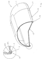
- a hollow body 10 is shown as a product of the method according to the invention from a domed half-shell 11 and a flat shell 12 made in an injection molding machine has been.
- the flat shell 12 has one after below or outside angled edge 13 on which the holding surface 14 is formed for a suitably designed tool.
- the holding surface 14 is exactly the connection area 15 opposite, in the one with high pressure a closed revolving thermoplastic connecting seam 16 has been injected.
- thermoplastic connecting seam 16 extends between the outer edge, partially from the lower edge 17 of the half-shell 11 is covered and the lower end of the half-shell 11. As a result, the thermoplastic connecting seam 16 is in the Hollow body 10 hardly recognizable as a connection and comes with one minimal cross section to fulfill the connection function.
- the hollow body 10 was in this way easily in the Injection molding machine manufactured without a subsequent separate operation by gluing, welding or the like. was required.
- the intended shape of the hollow body 10 was without any Shape impairment in the connection area 15 quickly and reproducibly manufactured, whereby to facilitate the overlapping hollow part edge merging, as in Figure 2, chamfers 24 and 25 are provided.
- FIG 2 shows a similar hollow body 10 ', with the deviating from the embodiment shown in Figure 1 the flat Half-shell with a groove 21 formed in from the outside in Connection area is formed on which the holding surface 14 'for reaching behind the tool against the injection pressure for the all-round thermoplastic connecting seam 16 ' is provided.
- the connection area 15 'does not only show one thermoplastic connecting seam 16 'with an approximately circular Cross-section, but also a quarter-circular arc molded receiving portion 22 at the lower end 17 'of upper half-shell and a quarter-circle-shaped indentation 23 on the outer edge of the flat shell 12 '.
- FIG 3 is a partially sectioned representation of a body 10 '', made of two identical half-shells that are curved in opposite directions 11 '' produced by the method according to the invention has been.
- the two half-shells 11 '' each have its mutually facing end 17 '' is a reinforced material Contact edge area 30 with an approximately 180 ° turned outwards Section 31.
- the holding surfaces 14 ' are each on the folded section 31, and for spraying a thermoplastic connecting seam 16 '' folded sections 31 radially with a quarter circle 22 '' recess.
- the thermoplastic seam 16 '' has an approximately circular cross section.
- the hollow body 10 ′′ also consists of two domes that are curved in opposite directions Half-shells 11 '' can be easily, quickly and hardly by visible from the outside without endangering the hollow shape, also after the Manufacture method according to the invention with secure tightness.
Landscapes
- Engineering & Computer Science (AREA)
- Manufacturing & Machinery (AREA)
- Mechanical Engineering (AREA)
- Injection Moulding Of Plastics Or The Like (AREA)
- Moulds For Moulding Plastics Or The Like (AREA)
- Lining Or Joining Of Plastics Or The Like (AREA)
Description
- Figur 1
- einen teilweise geschnittene perspektivische Darstellung eines Hohlkörpers aus einer gewölbten Halbschale und einer flachen Schale;
- Figur 2
- eine Darstellung gemäß Figur 1 mit einer von außen eingeformten Nut an der flachen Schale; und
- Figur 3
- einen nach dem Verfahren hergestellten Hohlkörper aus zwei gegensinnig gewölbten Halbschalen in perspektivischer teilgeschnittener Darstellung.
Claims (10)
- Verfahren zur Herstellung von thermoplastischen Hohlkörpern nach dem Spritzgießverfahren, wobei in einem Spritzgießwerkzeug zwei Hohlkörperteile (11, 12, 11', 12', 11") gebildet, nach ihrem Erstarren zusammengeführt und mit einer Naht (16, 16', 16") aus thermoplastischer Formmasse zur Verbindung mit hohem Druck umspritzt werden, und wobei an wenigstens einem Hohlkörperteil (12, 12', 11") nahe dem Verbindungsbereich (15, 15') eine den Hohlkörper gegen Verformungen infolge des Einwirkens der hohen Umspritzdrücke abstützende umlaufende Haltefläche (14, 14', 14") für ein werkzeugseitiges. Hintergreifen angeformt wird,
dadurch gekennzeichnet, dass an wenigstens einem der beiden Hohlkörperteile (11, 12, 11', 12', 11'') an dessen Verbindungsbereich (15, 15') eine materialverstärkte Anlage-Stoßkante zum Schwundausgleich angeformt wird. - Verfahren nach Anspruch 1, bei dem der Hohlkörper (10) aus einer gewölbten Halbschale (11) und aus einer flachen Schale (12) hergestellt wird,
dadurch gekennzeichnet, dass an der flachen Schale (12) für die horizontale innere Abstützung die Haltefläche (14) an einem nach außenabgewinkelten Rand (13) gebildet wird. - Verfahren nach Anspruch 1, bei dem der Hohlkörper (10') aus einer gewölbten Halbschale (11') und aus einer flachen Schale (12) hergestellt wird,
dadurch gekennzeichnet, dass an der flachen Schale (12') für die horizontale innere Abstützung die Haltefläche (14') als von außen eingeformte Nut (21) gebildet wird. - Verfahren nach Anspruch 2 oder 3,
dadurch gekennzeichnet, dass zwischen dem abgewinkelten Innenrand (13') der flachen Schale (12, 12') und dem unteren Ende (17) der gewölbten Halbschale (11, 11') ein Aufnahmebereich (22, 23) für eine thermoplastische Verbindungsnaht (16) geformt wird. - Verfahren nach einem der Ansprüche 2 bis 4,
dadurch gekennzeichnet, dass an dem nach außen abgewinkelten Rand (13) bzw. an der von außen eingeformten Nut (21) der flachen Schale (12, 12') oder/und an dem unteren Innenrand der Halbschale (11, 11') eine Anfasung (24, 25) gebildet wird. - Verfahren nach Anspruch 1, bei dem der Hohlkörper (10') aus zwei gegensinnig gewölbten Halbschalen (11'') hergestellt wird,
dadurch gekennzeichnet, dass, jeweils an den Halbschalen (11'') ein materialverstärkter Anlagenkantenbereich (30) mit einem um etwa 180° nach außen umgelegten Abschnitt (31) geformt wird,
wobei jeweils die Haltefläche (14'') an dem umgelegten Abschnitt (31) gebildet wird, und
wobei für das Aufspritzen einer thermoplastischen Verbindungsnaht (16") die Abschnitte (31) radial mit einer Aufnahmeeinformung (22") versehen werden. - Verfahren nach Anspruch 6,
dadurch gekennzeichnet, dass die Breite der Haltefläche (14") etwa in der Wandstärke der Halbschale (11'') nahe der Stoßkante gestaltet wird. - Verfahren nach Anspruch 6 oder 7,
dadurch gekennzeichnet, dass die Materialstärke des umgelegten Abschnitts (31) im Bereich der Stoßkante kleiner als im Bereich der Haltefläche (14 ") geformt wird. - Verfahren nach einem der vorangehenden Ansprüche,
dadurch gekennzeichnet, dass die Verbindungsnaht (16, 16', 16") mit einem annähernd kreisförmigen Querschnitt umspritzt wird. - Verfahren nach einem der vorangehenden Ansprüche,
dadurch gekennzeichnet, dass die Umspritzung zur Verbindung der beiden Hohlkörperteile (11, 12, 11', 12', 11'') über wenigstens zwei Anspritzpunkte vorgenommen wird.
Priority Applications (2)
| Application Number | Priority Date | Filing Date | Title |
|---|---|---|---|
| DE59810845T DE59810845D1 (de) | 1998-03-27 | 1998-03-27 | Verfahren zur Herstellung von thermoplastischen Hohlkörpern |
| EP19980105637 EP0950503B1 (de) | 1998-03-27 | 1998-03-27 | Verfahren zur Herstellung von thermoplastischen Hohlkörpern |
Applications Claiming Priority (1)
| Application Number | Priority Date | Filing Date | Title |
|---|---|---|---|
| EP19980105637 EP0950503B1 (de) | 1998-03-27 | 1998-03-27 | Verfahren zur Herstellung von thermoplastischen Hohlkörpern |
Publications (2)
| Publication Number | Publication Date |
|---|---|
| EP0950503A1 EP0950503A1 (de) | 1999-10-20 |
| EP0950503B1 true EP0950503B1 (de) | 2004-02-25 |
Family
ID=8231667
Family Applications (1)
| Application Number | Title | Priority Date | Filing Date |
|---|---|---|---|
| EP19980105637 Expired - Lifetime EP0950503B1 (de) | 1998-03-27 | 1998-03-27 | Verfahren zur Herstellung von thermoplastischen Hohlkörpern |
Country Status (2)
| Country | Link |
|---|---|
| EP (1) | EP0950503B1 (de) |
| DE (1) | DE59810845D1 (de) |
Cited By (4)
| Publication number | Priority date | Publication date | Assignee | Title |
|---|---|---|---|---|
| DE102007003413A1 (de) * | 2007-01-23 | 2008-07-24 | Wilo Ag | Pumpengehäuse aus Glasfaser-Spritzguss |
| USD639398S1 (en) | 2006-07-26 | 2011-06-07 | Colder Products Company | Fluid coupling |
| EP1986539B2 (de) † | 2006-02-16 | 2019-05-01 | BSH Hausgeräte GmbH | Geschirrspülmaschine mit sprühvorrichtung |
| IT202300011814A1 (it) * | 2023-06-09 | 2024-12-09 | Linea 3 S R L | Contenitore di una miscela liquida di alimentazione dei tergicristalli di un autoveicolo e metodo per realizzare tale contenitore |
Families Citing this family (1)
| Publication number | Priority date | Publication date | Assignee | Title |
|---|---|---|---|---|
| EP4736729A1 (de) * | 2024-10-31 | 2026-05-06 | Arçelik Anonim Sirketi | Geschirrspülmaschine mit einem personalisierten sprühelement |
Family Cites Families (4)
| Publication number | Priority date | Publication date | Assignee | Title |
|---|---|---|---|---|
| DE2501291A1 (de) * | 1975-01-15 | 1976-07-22 | Roehm Gmbh | Verfahren zur herstellung von hohlkoerpern nach dem spritzgiessverfahren |
| DE3405456C2 (de) * | 1984-02-16 | 1986-07-24 | Bayerische Motoren Werke AG, 8000 München | Verbindung zweier Bauteile, insbesondere zweier Kunststoff-Halbschalen für die Sauganlage einer Brennkraftmaschine |
| US5413743A (en) * | 1993-05-20 | 1995-05-09 | General Motors Corporation | Method of making a lamp assembly |
| JP3012914B2 (ja) * | 1994-12-28 | 2000-02-28 | 株式会社日本製鋼所 | 射出成形法による合成樹脂製中空製品およびその製造方法 |
-
1998
- 1998-03-27 EP EP19980105637 patent/EP0950503B1/de not_active Expired - Lifetime
- 1998-03-27 DE DE59810845T patent/DE59810845D1/de not_active Expired - Lifetime
Cited By (6)
| Publication number | Priority date | Publication date | Assignee | Title |
|---|---|---|---|---|
| EP1986539B2 (de) † | 2006-02-16 | 2019-05-01 | BSH Hausgeräte GmbH | Geschirrspülmaschine mit sprühvorrichtung |
| USD639398S1 (en) | 2006-07-26 | 2011-06-07 | Colder Products Company | Fluid coupling |
| USD642244S1 (en) | 2006-07-26 | 2011-07-26 | Colder Products Company | Fluid coupling |
| DE102007003413A1 (de) * | 2007-01-23 | 2008-07-24 | Wilo Ag | Pumpengehäuse aus Glasfaser-Spritzguss |
| IT202300011814A1 (it) * | 2023-06-09 | 2024-12-09 | Linea 3 S R L | Contenitore di una miscela liquida di alimentazione dei tergicristalli di un autoveicolo e metodo per realizzare tale contenitore |
| EP4474229A1 (de) * | 2023-06-09 | 2024-12-11 | LINEA 3 S.r.l. | Behälter für eine flüssigkeitsmischung zur versorgung der scheibenwischer eines kraftfahrzeugs und verfahren zur herstellung eines solchen behälters |
Also Published As
| Publication number | Publication date |
|---|---|
| DE59810845D1 (de) | 2004-04-01 |
| EP0950503A1 (de) | 1999-10-20 |
Similar Documents
| Publication | Publication Date | Title |
|---|---|---|
| DE19852553C2 (de) | Verfahren und Einrichtung zur Herstellung eines Kunstharzhohlteils, in welchem ein Zwischenelement vorgesehen ist | |
| EP0121207A2 (de) | Hohlkörper aus Kunststoffen | |
| EP0241009B1 (de) | Verfahren und Formwerkzeug zur Herstellung eines in ein Mauerwerk einsetzbaren Steigbügels | |
| DE20017288U1 (de) | Lenkrad mit Dekorelement | |
| EP0579799A1 (de) | Abstandhalter für einen in beton einzubettenden armierungsstab | |
| DE3405456C2 (de) | Verbindung zweier Bauteile, insbesondere zweier Kunststoff-Halbschalen für die Sauganlage einer Brennkraftmaschine | |
| DE2856462A1 (de) | Gehaeuse, insbesondere fahrzeugaufbau | |
| DE3935856C1 (de) | ||
| DE2555166A1 (de) | Zylinderkopf | |
| EP0950503A1 (de) | Verfahren zur Herstellung von thermoplastischen Hohlkörpern | |
| DE2523687A1 (de) | Verfahren und vorrichtung zur herstellung eines zusammengesetzten behaelters | |
| DE4241409C2 (de) | Verfahren sowie Vorrichtung zum Herstellen eines Bauteils durch Spritzen wenigstens zweier Elemente aus Kunststoff und durch Zusammenfügen dieser Elemente nach dem Spritzen | |
| DE2332462C3 (de) | Isolierkörper für Rohrbögen | |
| DE2511302C3 (de) | Verfahren zur Herstellung eines Wellendichtringes | |
| DE2821133B1 (de) | Verfahren zum Verbinden der Enden von auf Gehrung geschnittenen Hohlprofilen | |
| DE3445186C2 (de) | Wassereinlauf | |
| DE3328146A1 (de) | Stabfoermiges material und verfahren zu dessen herstellung | |
| DE1704130A1 (de) | Verfahren zur Herstellung eines Rohrabzweigers aus thermoplastischem,bei Zimmertemperatur hartem Kunststoff | |
| DE3017334C2 (de) | ||
| DE602005004880T2 (de) | Verbindungsstück für Bauteile | |
| EP0145012A2 (de) | Wassereinlauf | |
| DE10119246B4 (de) | Gelenkkette | |
| DE4216708A1 (de) | Rahmenaufbau fuer eine form zum expansionsformen | |
| DE8900015U1 (de) | Band- oder riemenförmiger Bauteil, insbesondere Uhrband | |
| DE1529799B1 (de) | Spritzgussform |
Legal Events
| Date | Code | Title | Description |
|---|---|---|---|
| PUAI | Public reference made under article 153(3) epc to a published international application that has entered the european phase |
Free format text: ORIGINAL CODE: 0009012 |
|
| 17P | Request for examination filed |
Effective date: 19981006 |
|
| AK | Designated contracting states |
Kind code of ref document: A1 Designated state(s): DE ES FR GB IT |
|
| AX | Request for extension of the european patent |
Free format text: AL;LT;LV;MK;RO;SI |
|
| AKX | Designation fees paid |
Free format text: DE ES FR GB IT |
|
| 17Q | First examination report despatched |
Effective date: 20010612 |
|
| GRAP | Despatch of communication of intention to grant a patent |
Free format text: ORIGINAL CODE: EPIDOSNIGR1 |
|
| GRAS | Grant fee paid |
Free format text: ORIGINAL CODE: EPIDOSNIGR3 |
|
| GRAA | (expected) grant |
Free format text: ORIGINAL CODE: 0009210 |
|
| AK | Designated contracting states |
Kind code of ref document: B1 Designated state(s): DE ES FR GB IT |
|
| PG25 | Lapsed in a contracting state [announced via postgrant information from national office to epo] |
Ref country code: IT Free format text: LAPSE BECAUSE OF FAILURE TO SUBMIT A TRANSLATION OF THE DESCRIPTION OR TO PAY THE FEE WITHIN THE PRESCRIBED TIME-LIMIT;WARNING: LAPSES OF ITALIAN PATENTS WITH EFFECTIVE DATE BEFORE 2007 MAY HAVE OCCURRED AT ANY TIME BEFORE 2007. THE CORRECT EFFECTIVE DATE MAY BE DIFFERENT FROM THE ONE RECORDED. Effective date: 20040225 Ref country code: GB Free format text: LAPSE BECAUSE OF FAILURE TO SUBMIT A TRANSLATION OF THE DESCRIPTION OR TO PAY THE FEE WITHIN THE PRESCRIBED TIME-LIMIT Effective date: 20040225 Ref country code: FR Free format text: LAPSE BECAUSE OF FAILURE TO SUBMIT A TRANSLATION OF THE DESCRIPTION OR TO PAY THE FEE WITHIN THE PRESCRIBED TIME-LIMIT Effective date: 20040225 |
|
| REG | Reference to a national code |
Ref country code: GB Ref legal event code: FG4D Free format text: NOT ENGLISH |
|
| REF | Corresponds to: |
Ref document number: 59810845 Country of ref document: DE Date of ref document: 20040401 Kind code of ref document: P |
|
| PG25 | Lapsed in a contracting state [announced via postgrant information from national office to epo] |
Ref country code: ES Free format text: LAPSE BECAUSE OF FAILURE TO SUBMIT A TRANSLATION OF THE DESCRIPTION OR TO PAY THE FEE WITHIN THE PRESCRIBED TIME-LIMIT Effective date: 20040605 |
|
| GBV | Gb: ep patent (uk) treated as always having been void in accordance with gb section 77(7)/1977 [no translation filed] |
Effective date: 20040225 |
|
| PLBE | No opposition filed within time limit |
Free format text: ORIGINAL CODE: 0009261 |
|
| STAA | Information on the status of an ep patent application or granted ep patent |
Free format text: STATUS: NO OPPOSITION FILED WITHIN TIME LIMIT |
|
| EN | Fr: translation not filed | ||
| 26N | No opposition filed |
Effective date: 20041126 |
|
| PGFP | Annual fee paid to national office [announced via postgrant information from national office to epo] |
Ref country code: DE Payment date: 20160331 Year of fee payment: 19 |
|
| REG | Reference to a national code |
Ref country code: DE Ref legal event code: R119 Ref document number: 59810845 Country of ref document: DE |
|
| PG25 | Lapsed in a contracting state [announced via postgrant information from national office to epo] |
Ref country code: DE Free format text: LAPSE BECAUSE OF NON-PAYMENT OF DUE FEES Effective date: 20171003 |