EP0949718A1 - Module de connexion/déconnexion de paires de conducteurs électriques isolés - Google Patents
Module de connexion/déconnexion de paires de conducteurs électriques isolés Download PDFInfo
- Publication number
- EP0949718A1 EP0949718A1 EP99400691A EP99400691A EP0949718A1 EP 0949718 A1 EP0949718 A1 EP 0949718A1 EP 99400691 A EP99400691 A EP 99400691A EP 99400691 A EP99400691 A EP 99400691A EP 0949718 A1 EP0949718 A1 EP 0949718A1
- Authority
- EP
- European Patent Office
- Prior art keywords
- contacts
- base
- module according
- housings
- pusher
- Prior art date
- Legal status (The legal status is an assumption and is not a legal conclusion. Google has not performed a legal analysis and makes no representation as to the accuracy of the status listed.)
- Granted
Links
- 239000004020 conductor Substances 0.000 title claims abstract description 36
- 238000006073 displacement reaction Methods 0.000 claims description 20
- 238000009413 insulation Methods 0.000 claims description 15
- 230000001012 protector Effects 0.000 claims description 13
- 238000003780 insertion Methods 0.000 claims description 10
- 230000037431 insertion Effects 0.000 claims description 10
- 230000000295 complement effect Effects 0.000 claims description 3
- 238000004873 anchoring Methods 0.000 claims description 2
- 230000002093 peripheral effect Effects 0.000 description 3
- 239000002184 metal Substances 0.000 description 2
- 230000000717 retained effect Effects 0.000 description 2
- 206010001488 Aggression Diseases 0.000 description 1
- 230000016571 aggressive behavior Effects 0.000 description 1
- 230000000712 assembly Effects 0.000 description 1
- 238000000429 assembly Methods 0.000 description 1
- 238000013461 design Methods 0.000 description 1
- 239000004519 grease Substances 0.000 description 1
- 239000012212 insulator Substances 0.000 description 1
- 238000012423 maintenance Methods 0.000 description 1
- 238000000034 method Methods 0.000 description 1
- 230000001681 protective effect Effects 0.000 description 1
- 238000000926 separation method Methods 0.000 description 1
- 238000012360 testing method Methods 0.000 description 1
- 238000013519 translation Methods 0.000 description 1
- 238000012795 verification Methods 0.000 description 1
Images


Classifications
-
- H—ELECTRICITY
- H01—ELECTRIC ELEMENTS
- H01R—ELECTRICALLY-CONDUCTIVE CONNECTIONS; STRUCTURAL ASSOCIATIONS OF A PLURALITY OF MUTUALLY-INSULATED ELECTRICAL CONNECTING ELEMENTS; COUPLING DEVICES; CURRENT COLLECTORS
- H01R4/00—Electrically-conductive connections between two or more conductive members in direct contact, i.e. touching one another; Means for effecting or maintaining such contact; Electrically-conductive connections having two or more spaced connecting locations for conductors and using contact members penetrating insulation
- H01R4/24—Connections using contact members penetrating or cutting insulation or cable strands
- H01R4/2416—Connections using contact members penetrating or cutting insulation or cable strands the contact members having insulation-cutting edges, e.g. of tuning fork type
- H01R4/242—Connections using contact members penetrating or cutting insulation or cable strands the contact members having insulation-cutting edges, e.g. of tuning fork type the contact members being plates having a single slot
- H01R4/2425—Flat plates, e.g. multi-layered flat plates
- H01R4/2429—Flat plates, e.g. multi-layered flat plates mounted in an insulating base
- H01R4/2433—Flat plates, e.g. multi-layered flat plates mounted in an insulating base one part of the base being movable to push the cable into the slot
-
- H—ELECTRICITY
- H01—ELECTRIC ELEMENTS
- H01R—ELECTRICALLY-CONDUCTIVE CONNECTIONS; STRUCTURAL ASSOCIATIONS OF A PLURALITY OF MUTUALLY-INSULATED ELECTRICAL CONNECTING ELEMENTS; COUPLING DEVICES; CURRENT COLLECTORS
- H01R13/00—Details of coupling devices of the kinds covered by groups H01R12/70 or H01R24/00 - H01R33/00
- H01R13/66—Structural association with built-in electrical component
- H01R13/665—Structural association with built-in electrical component with built-in electronic circuit
- H01R13/6666—Structural association with built-in electrical component with built-in electronic circuit with built-in overvoltage protection
-
- H—ELECTRICITY
- H01—ELECTRIC ELEMENTS
- H01R—ELECTRICALLY-CONDUCTIVE CONNECTIONS; STRUCTURAL ASSOCIATIONS OF A PLURALITY OF MUTUALLY-INSULATED ELECTRICAL CONNECTING ELEMENTS; COUPLING DEVICES; CURRENT COLLECTORS
- H01R2201/00—Connectors or connections adapted for particular applications
- H01R2201/16—Connectors or connections adapted for particular applications for telephony
-
- Y—GENERAL TAGGING OF NEW TECHNOLOGICAL DEVELOPMENTS; GENERAL TAGGING OF CROSS-SECTIONAL TECHNOLOGIES SPANNING OVER SEVERAL SECTIONS OF THE IPC; TECHNICAL SUBJECTS COVERED BY FORMER USPC CROSS-REFERENCE ART COLLECTIONS [XRACs] AND DIGESTS
- Y10—TECHNICAL SUBJECTS COVERED BY FORMER USPC
- Y10S—TECHNICAL SUBJECTS COVERED BY FORMER USPC CROSS-REFERENCE ART COLLECTIONS [XRACs] AND DIGESTS
- Y10S439/00—Electrical connectors
- Y10S439/922—Telephone switchboard protector
Definitions
- the present invention relates to a module for connecting / disconnecting pairs of insulated electrical conductors.
- modules are in particular intended for the constitution of connection and patching assemblies of connections between pairs of conductors.
- EP-A-0 248 743 discloses a modular device for connection of pairs of insulated conductors.
- This device includes a support insulator, two nested stacks of tubular contacts in the support, guide means allowing relative axial displacement, but not angular between each contact and the support, and an actuating screw ensuring this relative translation between two of the contacts side by side and the support.
- the contacts are all identical. Each of them has its two insulation-displacement ends, for connecting a conductor in one of the insulation displacement ends, and has one of its ends pluggable into the other end of another contact in each stack.
- the holder has plug-in sockets which are retained on a metal base and connected to earth and which retain internally between them the two contact stacks. Passages are provided in the sockets, being opposite the insulation-displacement ends of the contacts. They receive the electrical conductors, which are connected in the insulation displacement ends by the simultaneous relative displacement between the contacts side by side and one of the sockets, secured by actuation of the screw then anchoring in the base.
- Removal of stacked contacts can also be done by actuation of the screw and its removal from the base, for the resulting disengaging previously stacked contacts.
- This known device can also include a protective surge protector equipment connected to electrical conductors.
- This surge protector is removable mounted on an intermediate sleeve in the stacking of the sockets. he has two line protection terminals, connected to the two contacts of the two contact stacks, and a connected ground terminal electrically to the provided conductive screw.
- connection / disconnection device is relatively complex as long by the number of independent parts mounted separately from each other than by the resulting assembly / disassembly operations and duration for connecting / disconnecting pairs of conductors.
- the object of the present invention is to provide a module for connection / disconnection of pairs of conductors, design and implementation simplified work and thereby reduced cost.
- connection / disconnection modules in Figures 1 and 2 are described simultaneously by specifying their essential differences with regard to these figures.
- Each module has two connection plugs 1 and 2 and one insulating support 3, on which the two plugs are mounted opposite and come plug into each other and into the holder.
- sheet 1 contains the first two identical tubular contacts to each other, not visible but designated below by the reference 11, and a first pusher 12 movably mounted on a first end of these contacts.
- the pusher 12 maintains these side by side contacts and ensures the connection of a first pair of conductors in the first end of the contacts.
- It has two passages 13, provided transversely to the contacts and opposite their first end, for the driver reception.
- the second sheet 2 has similarly two second contacts identical to each other but not to the first, which are not visible in these figures, but designated below by the reference 21, and a second movable pusher 22 on the first end of these contacts. This second push-button ensures the two second contacts are held side by side. he has two passages 23 transverse to the second contacts and located opposite screw of their first end, for the connection of a second pair of conductors inserted in these passages at the second contacts.
- the second ends of the first two and second contacts are the plug-in ends of the plugs one inside the other.
- the support 3 defines a base 30 of overall rectangular shape and has a transverse connection stud projecting from a connection face 31 of the base.
- This pad is designated differently by the reference 5 in Figure 1 and the reference 6 in FIG. 6. It is of overall parallelepiped shape, the stud 6 being significantly more salient than the stud 5. It is provided on one of the parts base terminals. As a variant, this stud may be non-terminal, being median or not based.
- the pads 5 and 6 have the common function of ensuring the plugging of the plugs 1 and 2. They both have for this purpose, the first two housings interiors identical to each other, not visible in these figures 1 and 2, but designated below by reference 61. These first two dwellings, in one and the other of the pads, are provided side by side, are parallel to the base 30 and are open on either side of the stud, on two opposite faces for plugging in the plugs 1 and 2 in the plot.
- the pad 6 also provides an additional function of protection of equipment connected to the pairs of conductors connected by the connection / disconnection module of FIG. 2. It has for this purpose three additional housings, which are lateral for two of them 63 and lead on the one hand into the first two dwellings, and on the other hand onto the face of the stud 6 opposite the base, and which is median for the third 64 of these additional housing and opens on the one hand through the base 30 and on the other also leaves on the face of the stud 6 opposite the base.
- Two third contacts 65 are mounted in the two lateral housings 63 and a so-called earth contact 66 in the middle housing 64.
- connection / disconnection module of FIG. 2 comprises at correspondence with this pad 6 a three-pole surge protector module 7, which is plugged in on pad 6 and thus connects to the two third contacts 65 and to the contact of mass 66 in it.
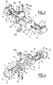
- FIGS. 3 and 4 and / or 5 and 6 relating to the module of connection / disconnection of figure 2, knowing that apart from the specific provisions for the additional function of the latter, the modules of connection / disconnection of Figures 1 and 2 are also identical to each other.
- the first two contacts 11 of the first plug 1 are tubular, while the second contacts 21 of the second plug 2 are flat.
- the first end of the first contacts has two slots insulation displacement opposites 14.
- the second opposite end also has two opposite slots 15, not self-stripping, but of elasticity of this end plug-in.
- the first end of the second contacts has an axial slot insulation displacement 24.
- the second end has another axial slot 25, not insulation displacement, but of elasticity of this second end. Its width is substantially equal to the inside diameter of the second end of each first contact, for their elastic plugging.
- the first pusher 12 defines a body comprising two pipes identical 17, which are projecting side by side on one side said before the pusher and receive the first ends of the first contacts.
- Each of these tubes has a slot 17A, which is superimposed on one of the slots 15 of one of the contacts 11 and comes above the slot 25 of one of the contacts 21 when the plugs 1 and 2 are plugged into pin 6 and one into the other.
- the passages 13 in this first pusher are defined by two other tubes, which are protruding side by side on an upper face of this pusher and are designated by these same references 13, to receive the two conductors to be connected simultaneously with the first two contacts in the first pusher 12.
- the pipes 13 are transverse to pipes 17 and open into the latter, respectively. They have only one open end, front or upper depending on the tubing, their other end being closed.
- the second pusher 22 has two grooves 27, internally deep and side by side, which receive the first ends of the second contacts 21 and open into two recesses 28 on the so-called front face of this pusher. It also includes the two passages 23, transverse to the grooves 27 and opening into them, to receive the two conductors to be connected in the first insulation displacement end of the contacts 21.
- the front ends grooves 27 and the upper ends of the passages 23 are only open, the opposite ends being closed.
- the first housings 61 for inserting the plugs 1 and 2 into the pad 6 and one inside the other are cylindrical in shape and have an internal diameter just intended for the insertion of the pipes 17 into them. They have a first opening circular 67, of the same diameter as them, for entering the pipes 17. They have a second adapted opening 69, rectangular, to receive the second plug-in ends of the second contacts 21. They also have a peripheral rim 68 around each second opening, which is complementary to each of the recesses 28 provided in the second pusher and fits into one of them.
- the two lateral contacts 65 in the stud are flat and straight contacts.
- the innermost end in the stud of each of these contacts forms a lug 65A, on which slide the slot 17A of one of the pipes 17, the slots 15 of one of the contacts 11 and the slot 25 of one of the contacts 21, when plugs 1 and 2 are plugged into the block and one into the other.
- the other so-called end upper of each of these contacts in the stud has an axial slot 65B of elastic clamping of the corresponding line tab of the surge protector plugging into this slot.
- Earth contact 66 in the stud is also a flat contact, more as long as the contacts 65, but not straight. It has a terminal portion cut into a U, which protrudes under the base, and whose terminal branch forms a friction spring 66A. This terminal friction spring 66A is substantially parallel at base 30 and at a relatively short distance from it. The other end of the earth contact 66 has an axial slot 66B, into which the surge protector ground tab.
- the pluggable surge protector module on the stud which was illustrated in Figure 2 is not shown in the other following figures. We understand easily as long as this module has a recess in its face lower, which is complementary to the stud and in which the two legs of line and the ground leg of the surge protector are protruding, so that the surge protector module plugs into the stud with the line and earth tabs plugging into the two contacts 65 and the contact 66.
- the base 30 serves as a slide for connection plug 2.
- base 30 has an axial slot 36, relatively narrow in its portion located on the side of stud 6 and wider in its opposite portion.
- the pusher 22 comprises at corresponds to a stepped foot 26 for its slide mounting on the base. The shouldered foot is inserted through the wide portion of the slot 36 and is retained and guided along the narrow portion of this slot.
- the support 3 is equipped for its removable mounting on a retaining rail and assembly of identical connection / disconnection modules side by side. Of peripheral edges protrude under the base. Longitudinal ledges 37 truncated in height with respect to the transverse edges and a tab transverse 38 integral with the transverse rim located under the stud 6 serve as support on the rail, on either side of it. An elastic tab 39 secured to the other transverse rim opposite the lug 38 secures the support 3 and thus of the connection / disconnection module on this rail. It is retractable using a screwdriver or the like for detaching the module as desired login / logout.
- This rail is a standard metal rail, in particular a "DIN 35" rail, on which the terminal contact shoe 66A of the earth contact is in contact elastic.
- Figures 5 and 6 show the connection / disconnection module in an initial position of the plugs 1 and 2 on the base 30 of the support 3, the pushers 12 and 22 being themselves in an initial position on their respective contacts 11 and 21.
- each of the pushers in the initial position of each of the pushers on its two contacts, the two passages 13 or 23 of the pusher are located just at the end of the insulation displacement slots 14 or 24 of contacts 11 and 21 and are therefore not closed through contacts.
- each of the pushers is movable in only one direction on its two contacts, from its initial position to a final position. In this final position of the pusher, the passages 13 or 23 will be blocked by the contacts concerned.
- a slight peripheral shoulder 11A on the intermediate part of the contacts 11 and two small side teeth 21A on the intermediate part of the contacts 21 allow a stable maintenance of the contacts in their pusher and only allow each of the pushers to move in one direction on the contacts.
- two large side teeth 21B on the flat contacts 21 are provided at substantially the same level as the bottom of their elasticity slot 25. They allow, on the one hand the stopping of the flat contacts 21 in their housings 61 in the stud 5, by abutment of the teeth 21B against the edge of the rectangular opening 69 of these dwellings. They also allow the stopping of the pusher 22 in its final position on the flat contacts, by abutment at the bottom of the recesses 27 against these teeth, while the pusher 22 itself abuts against the stud 6.
- the first sheet 1 is partially withdrawn or completely of support 3 for connection to the second plug 2 of that of pairs of conductors assigned to it. Partial or total withdrawal of the first sheet 1 is done by pulling on the pusher 12, which carries with it its two contacts tubular. It thus allows to sufficiently or completely free the face corresponding stud for the support of one of the jaws of the pliers against this face, while the other jaw will bear against the rear face of the pusher 22.
- the two conducting wires are inserted in the two passages 23 of the pusher 22.
- the clamp put in place to ensure that the pusher 22 and the pad 6 between its jaws, then actuates this pusher 22 in final position on its two contacts 21, themselves then in final position in the housings 61 of the stud 6.
- the resulting connection of the two conductors in the insulation displacement slots 24 of the contacts 21 is therefore permanent.
- the two isolated conductors of the other pair are inserted in the two passages 13 of the pusher 12 of the first sheet 1, this first plug being partially inserted in pin 6 after or before insertion conductors in the passages 13.
- the first pusher 12 is then actuated in the final position on its tubular contacts 11, using the clamp whose jaws take hold of the pusher 12 and the stud 6 or of the pusher 22 between they. This results, on the one hand, by plugging the contacts 11 fully into the housings. 21 of the pad and on the contacts 61 already in the final position therein.
- the result on the other hand the insertion of the pipes 17 to the bottom of the housings 61, then that at the same time the two conductors are engaged in the slots insulation displacement 14 of contacts 11.
- the connection of these two conductors to two contacts 11 is then also final.
- connection of the two pairs of conductors connected to plugs 1 and 2 results from the insertion of these two plugs into one another in the stud 6.
- Their disconnection for cutting the lines thus connected is done by drawing out plugs, using a screwdriver or the like lever operated or even finger, for the separation of one and / or the other of the plugs of the plot 6.
- An operation test can be performed similarly by unplugging the plugs.
- the pushers 12 and 13 are transparent to facilitate the direct verification of the correct connection of the conductors in the contacts.
- connection / disconnection module many reduced parts and pre-assembled to form the two plug-in plugs 1 and 2 in the support and thus one in the other, makes the operating mode very simple and easy, without special device integrated for this purpose in the module. It also reduces consequently the cost of the module and the duration of the operating mode.
- the module of connection / disconnection without associated protection includes the two plugs connection 1 and 2 and the insulating support 3 of the module in Figure 2 and a cover, which then replaces the surge protector module 7 and is used to come over the stud 6.
- This connection / disconnection module may or may not be fitted with two contacts 65 and of the earth contact 66 in the pad 6.
- Such a cover may have the form similar to that of the surge protector module, or of simplified form.
Abstract
Description
- deux fiches de connexion enfichables partiellement l'une dans l'autre et débrochables, formées pour une première desdites fiches par lesdits deux premiers contacts et un premier poussoir isolant monté sur lesdits premiers contacts et les retenant côte à côte, et pour la deuxième desdites fiches par lesdits deuxièmes contacts et un deuxième poussoir isolant monté sur ceux-ci et les retenant côte à côte, le poussoir de chacune desdites fiches étant monté mobile sur une première extrémité autodénudante des deux contacts de la fiche dans une seule direction vers la deuxième extrémité dite d'enfichage de ces mêmes contacts, pour le raccordement de l'une des paires de conducteurs dans la première extrémité autodénudante des deux contacts de ladite fiche, et
- ledit support comportant une base et un plot de connexion, ledit plot étant saillant sur une face de connexion de ladite base et pourvu de deux premiers logements intérieurs et côte à côte, lesdits premiers logements étant parallèles à ladite base et ouverts de part et d'autre sur deux faces latérales opposées dudit plot, pour l'enfichage des secondes extrémités d'enfichage des contacts desdites première et deuxième fiches dans lesdits premiers logements et pour l'enfichage résultant desdites fiches l'une dans l'autre, par les deux faces latérales opposées dudit plot, respectivement.
- lesdits premiers contacts sont des contacts tubulaires et lesdits deuxièmes contacts sont des contacts plats, le diamètre intérieur des deuxièmes extrémités des premiers contacts et la largeur des deuxièmes extrémités des deuxièmes contacts étant sensiblement identiques.,
- lesdites deuxièmes extrémités desdits premiers et deuxièmes contacts présentent chacune au moins une fente d'élasticité,
- ledit premier poussoir comporte deux premières tubulures identiques et côte à côte, dans lesquelles sont montés lesdits premiers contacts, et deux deuxièmes tubulures identiques et côte à côte, disposées transversalement aux premières tubulures, débouchant dans celles-ci et affectées à la réception des deux conducteurs isolés de l'une desdites paires de conducteurs,
- ledit deuxième poussoir comporte deux rainures profondes identiques parallèles et côte à côte, dans lesquelles sont montés lesdits deuxièmes contacts, et deux passages prévus côte à côte transversalement aux rainures et débouchant dans celles-ci, pour la réception des deux conducteurs de l'autre des paires,
- le module comporte en outre un dispositif modulaire parasurtenseur embrochable sur ledit plot, sur la face de celui-ci opposée à ladite base,
- ledit plot comporte deux deuxièmes logements identiques, prévus transversalement auxdits premiers logements et débouchant d'une part dans ceux-ci et d'autre part sur la face du plot opposée à ladite base, et un troisième logement médian, parallèle et disposé entre lesdits deuxièmes logements et débouchant d'une part à travers ladite base et d'autre part sur la face opposée à la base dudit plot, et comporte deux troisièmes contacts montés chacun dans l'un desdits deuxièmes logements et un contact de masse monté dans ledit troisième logement en étant saillant sur la face de la base opposée à celle dite de connexion.
- la figure 1 est une vue en perspective d'un module de connexion/déconnexion selon l'invention, sans protection associée à ce module,
- la figure 2 est une vue en perspective d'un module de connexion/déconnexion selon l'invention, à protection associée à ce module,
- les figures 3 et 4 sont deux vues recto et verso en perspective éclatée du module de la figure 2, et
- les figures 5 et 6 sont deux vues en coupe du module de la figure 2.
Claims (16)
- Module de connexion/déconnexion de paires de conducteurs électriques, comportant un support isolant et deux premiers et deux deuxièmes contacts autodénudants et partiellement enfichables les uns dans les autres, caractérisé en ce qu'il comporte :deux fiches de connexion (1, 2) enfichables partiellement l'une dans l'autre et débrochables, formées pour une première (1) desdites fiches par lesdits deux premiers contacts (11) et un premier poussoir isolant (12) monté sur lesdits premiers contacts et les retenant côte à côte, et pour la deuxième (2) desdites fiches par lesdits deuxièmes contacts (21) et un deuxième poussoir isolant (22) monté sur ceux-ci et les retenant côte à côte, le poussoir (12, 22) de chacune desdites fiches étant monté mobile sur une première extrémité autodénudante (14, 24) des deux contacts de la fiche dans une seule direction vers la deuxième extrémité (15, 25) dite d'enfichage de ces mêmes contacts, pour le raccordement de l'une des paires de conducteurs dans la première extrémité autodénudante des deux contacts de ladite fiche, etledit support (3) comportant une base (30) et un plot de connexion (6), ledit plot étant saillant sur une face de connexion de ladite base et pourvu de deux premiers logements (61) intérieurs et côte à côte, lesdits premiers logements (61) étant parallèles à ladite base et ouverts de part et d'autre sur deux faces latérales opposées dudit plot, pour l'enfichage des secondes extrémités d'enfichage des contacts desdites première et deuxième fiches dans lesdits premiers logements et pour l'enfichage résultant desdites fiches l'une dans l'autre, par les deux faces latérales opposées dudit plot, respectivement.
- Module selon la revendication 1, caractérisé en ce que lesdits premiers contacts (11) sont des contacts tubulaires et lesdits deuxièmes contacts (21) sont des contacts plats, le diamètre intérieur des deuxièmes extrémités des premiers contacts et la largeur des deuxièmes extrémités des deuxièmes contacts étant sensiblement identiques.
- Module selon la revendication 2, caractérisé en ce que les deuxièmes extrémités desdits premiers et deuxièmes contacts (11, 21) présentent chacune au moins une fente d'élasticité (15, 25).
- Module selon l'une des revendications 1 à 3, caractérisé en ce que lesdits premiers et deuxièmes contacts (11, 21) présentent des moyens d'ancrage (11A, 21A), prévus sur une portion intermédiaire de chacun d'eux, pour n'autoriser le déplacement de chacun desdits poussoirs (12, 22) que de ladite position initiale à ladite position finale.
- Module selon l'une des revendications 3 et 4, caractérisé en ce que lesdits premiers logements (61) présentent chacun une première ouverture circulaire (67) et une deuxième ouverture rectangulaire (69), sur lesdites deux faces latérales opposées dudit plot (6) respectivement.
- Module selon la revendication 5, caractérisé en ce que ledit premier poussoir (12) comporte deux premières tubulures identiques et côte à côte (17), dans lesquelles sont montés lesdits premiers contacts (11), et deux deuxièmes tubulures identiques et côte à côte (13), disposées transversalement aux premières tubulures, débouchant dans celles-ci et affectées à la réception des deux conducteurs isolés de l'une desdites paires de conducteurs.
- Module selon la revendication 6, caractérisé en ce que lesdites premières tubulures (17) comportent au moins une fente terminale (17A) et sont de diamètre extérieur sensiblement égal au diamètre de ladite première ouverture circulaire (67) desdits premiers logements (61), pour s'enficher dans ceux-ci.
- Module selon l'une des revendications 5 à 7, caractérisé en ce que ledit deuxième poussoir (22) comporte deux rainures profondes identiques (27) parallèles et côte à côte, dans lesquelles sont montés lesdits deuxièmes contacts, et deux passages (23) prévus côte à côte transversalement aux rainures et débouchant dans celles-ci, pour la réception des deux conducteurs de l'autre des paires.
- Module selon la revendication 8, caractérisé en ce que des moyens complémentaires d'emboitement (68, 28) sont prévus d'une part autour de la deuxième ouverture desdits premiers logements (61) dudit plot et d'autre part autour de l'extrémité correspondante des rainures (27) dudit deuxième poussoir (22).
- Module selon l'une des revendications 8 et 9, caractérisé en ce que ladite base (30) dudit support et au moins ledit deuxième poussoir (22) comportent des moyens de guidage (36, 26), pour le guidage en coulisseau dudit deuxième poussoir sur ladite base.
- Module selon la revendication 10, caractérisé en ce que lesdits moyens de guidage comportent une fente axiale de guidage (36) sur la base et un pied de coulisseau (26) sur ledit deuxième poussoir.
- Module selon l'une des revendications 1 à 11, caractérisé en ce que ladite base (30) est pourvue de pattes (38, 39) de maintien sur un rail, dont au moins l'une est élastiquement escamotable, pour un montage amovible du module sur le rail.
- Module selon l'une des revendications 1 à 12, caractérisé en ce qu'il comporte en outre un dispositif modulaire parasurtenseur (7) embrochable sur ledit plot (6), sur la face de celui-ci opposée à ladite base (30).
- Module selon l'une des revendications 1 à 12, caractérisé en ce qu'il comporte un cache embrochable sur ledit plot (6) pour coiffer la face de celui-ci opposée à ladite base (30).
- Module selon l'une des revendications 13 et 14, caractérisé en ce que ledit plot (6) comporte deux deuxièmes logements identiques (63), prévus transversalement auxdits premiers logements (61) et débouchant d'une part dans ceux-ci et d'autre part sur la face du plot opposée à ladite base, et un troisième logement médian (64), parallèle et disposé entre lesdits deuxièmes logements et débouchant d'une part à travers ladite base et d'autre part sur la face opposée à la base dudit plot, et comporte deux troisièmes contacts (65) montés chacun dans l'un desdits deuxièmes logements et un contact de masse (66) monté dans ledit troisième logement et saillant sur la base (30), sur la face de la base opposée à celle dite de connexion (32).
- Module selon la revendication 15, caractérisé en ce que la partie dudit contact de masse saillante sur la base forme un frotteur terminal (66A) de raccordement à la masse.
Applications Claiming Priority (2)
| Application Number | Priority Date | Filing Date | Title |
|---|---|---|---|
| FR9804433 | 1998-04-09 | ||
| FR9804433A FR2777389B1 (fr) | 1998-04-09 | 1998-04-09 | Module de connexion/deconnexion de paires de conducteurs electriques isoles |
Publications (2)
| Publication Number | Publication Date |
|---|---|
| EP0949718A1 true EP0949718A1 (fr) | 1999-10-13 |
| EP0949718B1 EP0949718B1 (fr) | 2006-07-12 |
Family
ID=9525048
Family Applications (1)
| Application Number | Title | Priority Date | Filing Date |
|---|---|---|---|
| EP99400691A Expired - Lifetime EP0949718B1 (fr) | 1998-04-09 | 1999-03-22 | Module de connexion/déconnexion de paires de conducteurs électriques isolés |
Country Status (5)
| Country | Link |
|---|---|
| US (1) | US6120317A (fr) |
| EP (1) | EP0949718B1 (fr) |
| DE (1) | DE69932278T2 (fr) |
| ES (1) | ES2268833T3 (fr) |
| FR (1) | FR2777389B1 (fr) |
Families Citing this family (2)
| Publication number | Priority date | Publication date | Assignee | Title |
|---|---|---|---|---|
| US6604957B2 (en) * | 2001-04-20 | 2003-08-12 | Woodhead Industries, Inc. | Field-attachable connector |
| JP6952462B2 (ja) * | 2016-12-15 | 2021-10-20 | スリーエム イノベイティブ プロパティズ カンパニー | 電線収容体、コネクタアセンブリ、及び防水性コネクタ |
Citations (2)
| Publication number | Priority date | Publication date | Assignee | Title |
|---|---|---|---|---|
| GB2261773A (en) * | 1991-11-15 | 1993-05-26 | Egerton A C Ltd | Transmission line connectors and assemblies thereof |
| FR2725312A1 (fr) * | 1994-09-29 | 1996-04-05 | Whitaker Corp | Assemblage de connecteur electrique pour telecommunications |
Family Cites Families (2)
| Publication number | Priority date | Publication date | Assignee | Title |
|---|---|---|---|---|
| DE7421399U (de) * | 1974-06-22 | 1975-09-04 | Feierabend H Gmbh | Furnierschwarte |
| NL9301050A (nl) * | 1993-06-16 | 1995-01-16 | Connector Systems Tech Nv | Tweezijdige connector voor de aansluiting op een electrische kabel. |
-
1998
- 1998-04-09 FR FR9804433A patent/FR2777389B1/fr not_active Expired - Lifetime
-
1999
- 1999-03-22 DE DE69932278T patent/DE69932278T2/de not_active Expired - Fee Related
- 1999-03-22 ES ES99400691T patent/ES2268833T3/es not_active Expired - Lifetime
- 1999-03-22 EP EP99400691A patent/EP0949718B1/fr not_active Expired - Lifetime
- 1999-04-07 US US09/287,287 patent/US6120317A/en not_active Expired - Fee Related
Patent Citations (2)
| Publication number | Priority date | Publication date | Assignee | Title |
|---|---|---|---|---|
| GB2261773A (en) * | 1991-11-15 | 1993-05-26 | Egerton A C Ltd | Transmission line connectors and assemblies thereof |
| FR2725312A1 (fr) * | 1994-09-29 | 1996-04-05 | Whitaker Corp | Assemblage de connecteur electrique pour telecommunications |
Also Published As
| Publication number | Publication date |
|---|---|
| FR2777389A1 (fr) | 1999-10-15 |
| DE69932278D1 (de) | 2006-08-24 |
| EP0949718B1 (fr) | 2006-07-12 |
| FR2777389B1 (fr) | 2000-05-12 |
| ES2268833T3 (es) | 2007-03-16 |
| US6120317A (en) | 2000-09-19 |
| DE69932278T2 (de) | 2007-07-12 |
Similar Documents
| Publication | Publication Date | Title |
|---|---|---|
| EP1916743B1 (fr) | Appareil électrique comprenant au moins une borne de raccordement à ressort | |
| EP2849287B1 (fr) | Dispositif de raccordement électrique d'au moins un conducteur dans une borne appartenant à un appareil électrique | |
| EP0633704B1 (fr) | Dispositif terminal d'interconnexion téléphonique d'abonné | |
| FR2662042A1 (fr) | Dispositif de connexion de lignes telephoniques, ce dispositif comportant au moins un module enfichable de protection contre les surtensions. | |
| WO2006048530A1 (fr) | Element de bornier et connecteur sans vis | |
| EP0578576B1 (fr) | Borne de connexion électrique | |
| EP2680379B1 (fr) | Ensemble d'appareils électriques modulaires avec dispositif de verrouillage sur un rail de montage | |
| FR2930080A3 (fr) | Fiche ou prise industrielle equipee de bornes a pince a ressort avec actionneurs | |
| EP0805605A1 (fr) | Organe de branchement pour réseau de transmission, en particulier pour réseau téléphonique ou informatique | |
| EP1026782B1 (fr) | Bloc d'interconnexion pour appareils électriques | |
| EP3487006B1 (fr) | Système électrique comprenant un appareil électrique et un module de connexion interchangeable | |
| EP0949718B1 (fr) | Module de connexion/déconnexion de paires de conducteurs électriques isolés | |
| EP1278224B1 (fr) | Dispositif de raccordement électrique de deux appareils électriques montés côte à côte sur un mème support de montage | |
| FR2514956A1 (fr) | Dispositif de connexion a enfichage | |
| FR2936367A1 (fr) | Connecteur electrique | |
| EP3975353A1 (fr) | Dispositif de distribution électrique | |
| FR2691846A1 (fr) | Prise de courant électrique à contact auto-dénudant. | |
| EP3651273A1 (fr) | Dispositif de raccordement electrique des bornes aval d'un appareil de protection electrique | |
| EP0609136B1 (fr) | Connecteur terminal de jarretière | |
| FR2815180A1 (fr) | Connecteur a plots amovibles pour canalisation electrique | |
| FR2813997A1 (fr) | Dispositif de liaison d'un conducteur a une piste conductrice | |
| FR2655207A1 (fr) | Connecteur electrique comportant des moyens perfectionnes de retenue de bornes. | |
| EP1353408B1 (fr) | Collecteur électrique | |
| CH716357A2 (fr) | Appareil modulaire électrique muni d'un élément de blocage. | |
| FR2626123A1 (fr) | Adaptateur gigogne pour conjoncteur telephonique |
Legal Events
| Date | Code | Title | Description |
|---|---|---|---|
| PUAI | Public reference made under article 153(3) epc to a published international application that has entered the european phase |
Free format text: ORIGINAL CODE: 0009012 |
|
| AK | Designated contracting states |
Kind code of ref document: A1 Designated state(s): CH DE ES GB LI |
|
| AX | Request for extension of the european patent |
Free format text: AL;LT;LV;MK;RO;SI |
|
| 17P | Request for examination filed |
Effective date: 20000413 |
|
| AKX | Designation fees paid |
Free format text: CH DE ES GB LI |
|
| RAP1 | Party data changed (applicant data changed or rights of an application transferred) |
Owner name: NEXANS |
|
| GRAP | Despatch of communication of intention to grant a patent |
Free format text: ORIGINAL CODE: EPIDOSNIGR1 |
|
| GRAS | Grant fee paid |
Free format text: ORIGINAL CODE: EPIDOSNIGR3 |
|
| GRAA | (expected) grant |
Free format text: ORIGINAL CODE: 0009210 |
|
| AK | Designated contracting states |
Kind code of ref document: B1 Designated state(s): CH DE ES GB LI |
|
| REG | Reference to a national code |
Ref country code: GB Ref legal event code: FG4D Free format text: NOT ENGLISH |
|
| REG | Reference to a national code |
Ref country code: CH Ref legal event code: EP |
|
| REF | Corresponds to: |
Ref document number: 69932278 Country of ref document: DE Date of ref document: 20060824 Kind code of ref document: P |
|
| GBT | Gb: translation of ep patent filed (gb section 77(6)(a)/1977) |
Effective date: 20061002 |
|
| REG | Reference to a national code |
Ref country code: ES Ref legal event code: FG2A Ref document number: 2268833 Country of ref document: ES Kind code of ref document: T3 |
|
| PLBE | No opposition filed within time limit |
Free format text: ORIGINAL CODE: 0009261 |
|
| STAA | Information on the status of an ep patent application or granted ep patent |
Free format text: STATUS: NO OPPOSITION FILED WITHIN TIME LIMIT |
|
| 26N | No opposition filed |
Effective date: 20070413 |
|
| REG | Reference to a national code |
Ref country code: CH Ref legal event code: PL |
|
| PG25 | Lapsed in a contracting state [announced via postgrant information from national office to epo] |
Ref country code: CH Free format text: LAPSE BECAUSE OF NON-PAYMENT OF DUE FEES Effective date: 20070331 Ref country code: LI Free format text: LAPSE BECAUSE OF NON-PAYMENT OF DUE FEES Effective date: 20070331 |
|
| PGFP | Annual fee paid to national office [announced via postgrant information from national office to epo] |
Ref country code: DE Payment date: 20090320 Year of fee payment: 11 |
|
| PGFP | Annual fee paid to national office [announced via postgrant information from national office to epo] |
Ref country code: ES Payment date: 20100324 Year of fee payment: 12 |
|
| PGFP | Annual fee paid to national office [announced via postgrant information from national office to epo] |
Ref country code: GB Payment date: 20100322 Year of fee payment: 12 |
|
| PG25 | Lapsed in a contracting state [announced via postgrant information from national office to epo] |
Ref country code: DE Free format text: LAPSE BECAUSE OF NON-PAYMENT OF DUE FEES Effective date: 20101001 |
|
| GBPC | Gb: european patent ceased through non-payment of renewal fee |
Effective date: 20110322 |
|
| PG25 | Lapsed in a contracting state [announced via postgrant information from national office to epo] |
Ref country code: GB Free format text: LAPSE BECAUSE OF NON-PAYMENT OF DUE FEES Effective date: 20110322 |
|
| REG | Reference to a national code |
Ref country code: ES Ref legal event code: FD2A Effective date: 20120424 |
|
| PG25 | Lapsed in a contracting state [announced via postgrant information from national office to epo] |
Ref country code: ES Free format text: LAPSE BECAUSE OF NON-PAYMENT OF DUE FEES Effective date: 20110323 |