EP0949502A2 - Vorrichtung zum Nachweis eines Fluoreszenzfarbstoffs - Google Patents
Vorrichtung zum Nachweis eines Fluoreszenzfarbstoffs Download PDFInfo
- Publication number
- EP0949502A2 EP0949502A2 EP98123363A EP98123363A EP0949502A2 EP 0949502 A2 EP0949502 A2 EP 0949502A2 EP 98123363 A EP98123363 A EP 98123363A EP 98123363 A EP98123363 A EP 98123363A EP 0949502 A2 EP0949502 A2 EP 0949502A2
- Authority
- EP
- European Patent Office
- Prior art keywords
- detected
- light
- fluorescent dye
- fluorescent
- glass plate
- Prior art date
- Legal status (The legal status is an assumption and is not a legal conclusion. Google has not performed a legal analysis and makes no representation as to the accuracy of the status listed.)
- Withdrawn
Links
- 0 C*1CCCC1 Chemical compound C*1CCCC1 0.000 description 1
Images


Classifications
-
- G—PHYSICS
- G01—MEASURING; TESTING
- G01N—INVESTIGATING OR ANALYSING MATERIALS BY DETERMINING THEIR CHEMICAL OR PHYSICAL PROPERTIES
- G01N21/00—Investigating or analysing materials by the use of optical means, i.e. using sub-millimetre waves, infrared, visible or ultraviolet light
- G01N21/62—Systems in which the material investigated is excited whereby it emits light or causes a change in wavelength of the incident light
- G01N21/63—Systems in which the material investigated is excited whereby it emits light or causes a change in wavelength of the incident light optically excited
- G01N21/64—Fluorescence; Phosphorescence
- G01N21/645—Specially adapted constructive features of fluorimeters
- G01N21/648—Specially adapted constructive features of fluorimeters using evanescent coupling or surface plasmon coupling for the excitation of fluorescence
-
- G—PHYSICS
- G01—MEASURING; TESTING
- G01N—INVESTIGATING OR ANALYSING MATERIALS BY DETERMINING THEIR CHEMICAL OR PHYSICAL PROPERTIES
- G01N2201/00—Features of devices classified in G01N21/00
- G01N2201/06—Illumination; Optics
- G01N2201/065—Integrating spheres
Definitions
- the invention relates to a device for detecting a fluorescent dye in a sample with a device for exciting the fluorescent dye to be detected, the one light coupling device through which light to excite of the fluorescent dye can be coupled into the device, and one for application of the sample provided surface, and with a device for detection of fluorescent radiation caused by the fluorescent dye to be detected has been issued.
- Such a device is from the article "A Planar Indium Phosphate Monomode Waveguide Evanescent Field Immunosensor "by A.N. Sloper, J.K. Deacon and M.T. Flanagan, in Sensors and Actuators, B1 (1990), pages 589-591.
- this article discloses a first embodiment in which a thin film waveguide is provided on a glass substrate. Through a light coupling device becomes monochromatic laser light in the thin film waveguide so coupled that it passes parallel to the surface of the thin film waveguide the same is directed. Fluorescent dye applied in a on the waveguide Sample is contained by the evanescent field located along the Thin film waveguide excited laser radiation. That through the depletion of the fluorescent dye is finally emitted with a Detected photomultiplier.
- this article discloses a second embodiment of the one described above Device in which the device for exciting the fluorescent dye to be detected provided in the form of a glass plate with a light coupling device is, wherein monochromatic laser light through the light coupling device is coupled into the glass plate so that it is totally reflected by the Glass plate is passed.
- the invention has for its object the known device for detecting a Fluorescent dye to improve the probability of detection is increased.
- a device of the type mentioned at the outset is characterized by a cavity that has a highly reflective inner surface, a first, the device for exciting the fluorescent dye to be detected opposite opening and a second, opposite the device for detection Has opening.
- the device for exciting the fluorescent dye to be detected on the surface of which the sample is applied, the first opening of the cavity is almost half of the emitted fluorescence radiation in irradiated the cavity. Because the cavity continues to be a highly reflective interior Has surface, the radiation radiated into the cavity can be almost there Spread without loss until it is detected by a detector.
- the highly reflective Surface barium sulfate or spectral Such surfaces have a reflectivity up to 99.8%. Accordingly, the reflection losses in the cavity be kept very small.
- each further device provided for detecting opposite openings in the cavity be.
- this arrangement allows the measurement of a dye at an excitation wavelength, but at the same time at different wavelengths of fluorescent radiation. Because such simultaneous measurements of fluorescence radiation at different Wavelengths are not possible with the known devices, according to the invention the time to carry out the measurement of the fluorescent radiation different wavelengths can be reduced by a factor of N if N is the number of the different wavelengths of fluorescence radiation.
- the fluorescent radiation can be several Fluorescent dyes detected at different wavelengths become.
- the devices for detection are provided light-tight in their corresponding openings in the cavity.
- each device for detecting one Have photomultiplier is configured to detect one Have photomultiplier.
- each device for detection can comprise a color filter device, which are tuned to the wavelength of the fluorescence radiation to be detected is.
- each device for detection can be provided with collimation optics become.
- a blocking filter device before the first opening of the A blocking filter device can be provided in the cavity, which device is used for excitation Blocks light and allows the fluorescence radiation to be detected to pass through.
- This measure can be used to avoid using the excitation Laser light, for example due to the inevitable micro-roughness of the glass surface, is scattered into the cavity and there the detection of the fluorescent radiation unfavorably overlaid.
- such a notch filter device can be replaced by a state of the art Technology known interference filter can be realized.
- this filter can be compared to the device be inclined to excite the fluorescent dye to be detected.
- the device for excitation of the fluorescent dye or fluorescent dyes to be detected in the form of a glass plate, which in particular has a relatively high refractive index, in particular of n> 1.46, such as pyrex glass or synthetic Quartz.
- the light coupling device in the form of an optically tight provided on the glass plate prism or in the form of a grating coupler is through the light coupling device, the light for exciting the fluorescent dye or the fluorescent dyes are so coupled into the glass plate, that it is passed through the glass plate with total reflection.
- the device for exciting the fluorescent dye to be detected or fluorescent dye to be detected be in the form of a thin film waveguide.
- This thin film waveguide can comprise, for example, Ta 2 O 5 .
- the light coupling device can be a Have grating couplers, the light for excitation of the fluorescent dye to be detected or the fluorescent dyes to be detected in the thin-film waveguide that it is parallel to the surface of the thin film waveguide is guided by this.
- all previously formed arrangements can a light decoupling device for the in the device for excitation of the fluorescent dye or fluorescent dyes to be detected coupled light may be provided.
- the light decoupling device can be ground by a provided the light coupling device opposite end surface of the glass plate be.
- the launched light can advantageously be coupled out by a grating coupler.
- the outcoupled light can be caught in a light trap, so that an uncontrolled re-entry into the device to excite the detected Fluorescent dye or the fluorescent dyes to be detected is avoided.
- FIG. 1 shows a first embodiment of a device 100 for detecting a Fluorescent dye F shown in a sample P according to the present invention.
- the device 100 comprises means for exciting the contained in the sample P.
- Fluorescent dye F which is provided in the form of a glass plate 110.
- This glass plate 110 consists of a glass with a relatively high refractive index.
- Pyrex glass with n 1.478 or a synthetic one can be used for the glass plate 110
- the glass plate 110 has a light coupling device in the form of an optical Prism 111 lying tight on the glass plate, through which light for excitation of the fluorescent dye can be coupled into the glass plate 110.
- the glass plate 110 comprises a surface 112 on which those to be detected Sample P containing fluorescent dye F is applied.
- a cavity 130 which in the present case is spherical is formed, the surface 112 on which the sample is applied is towards a first opening 132 of the cavity 130.
- the size of the spherical cavity 130 is in the embodiment shown in FIG. 1 80 mm.
- the cavity 130 includes a highly reflective inner surface 131, for example Include barium sulfate or spectral. With this special coating 99.8% reflectivity of the inner surface can be achieved.
- a second opening 133 is provided in the cavity 130, into which one Detection device 120 for detecting fluorescence radiation which is emitted by the fluorescent dye F to be detected has been emitted, for example a Photomultiplier device used.
- the operation of the device 100 is described below.
- the prism 111 emits light that corresponds to the excitation wavelength contains, or monochromatic laser light of the excitation wavelength in the glass plate 110 coupled.
- the monochromatic is planted in the glass plate 110 Laser light continues through several total reflections until it finally hits one of the Prism 111 opposite side emerges from the glass plate 110.
- the evanescent becomes Field of laser radiation used to excite the fluorescent dye F.
- the fluorescent radiation emitted by the excited fluorescent dye is irradiated into cavity 130, and finally after several total reflections detected on the highly reflective surface 131 by the detector 120.
- the fluorescence radiation generally has no preferred direction in the present arrangement approximately 50% of the intensity of the fluorescent radiation in the cavity 130, where it can finally be detected, irradiated.
- the fluorescence radiation is in the device according to the invention collected in the cavity 130 from a solid angle of almost 2 ⁇ steradiene and detected there.
- the device 100 shown in FIG. 1 can be changed in a variety of ways.
- the prism 111 can be used by other known light coupling devices, such as being replaced by a grating coupler.
- the cavity 130 can also have other geometric shapes, such as, for example have a cube shape or the like. Compared to that shown in Fig. 1 spherical arrangement, however, the number of reflections of the Increase fluorescence radiation in the cavity until it is detected by the detector, which may can increase the reflection losses in the cavity.
- the detector 120 is in the form of a photomultiplier in the present embodiment intended.
- a color filter can preferably be placed in front of the photomultiplier be emitted on the fluorescent dye F to be detected Wavelength is tuned.
- the reflection losses in the cavity 130 are to be reduced further, it makes sense to insert the detector 120 light-tight into the opening 133.
- the detector can be provided with collimation optics become.
- a monochromatic beam through the light coupling device into the Glass plate is coupled
- the device shown in Fig. 1 can also with two or several excitation wavelengths can be operated.
- the suggestion be modulated in the frequency domain, and the fluorescent radiation with the respective Frequency detected by an appropriately controlled detector device become.
- the device 100 is arranged so that the cavity 130 under the Excitation device 120 is located.
- the device 100 can also, in particular if liquid samples are to be examined, provide that the Cavity 130 lies above the excitation device 120.
- sample to be examined can also be used to examine liquid samples Sample applied to the glass plate 120 in the arrangement shown in FIG. 1 become. In this case, the fluorescence radiation passes through the glass plate, before entering the cavity.
- FIG. 2 shows a second embodiment of a device 200 for the detection of a Fluorescent dye F shown in a sample P.
- This device differs from that shown in Fig. 1 in that in addition to a first detector device 220 further detector devices 221 and 222, and a notch filter 240 are provided.
- a Glass plate 210 provided device for exciting the fluorescent dye to be detected provided with a light decoupling device 213, to which a Light trap 214 connects.
- the light plate 210 comprises an outcoupling device 213 which by sanding the end face of the glass plate 210, that of the light coupling device 211 opposite, is provided.
- the angle of the cut 213 with respect to the surface 212 of the glass plate is chosen so that the light from the Glass plate 210 can emerge unhindered, for example vertically. This will Avoided that light that has already passed through the glass plate back into the Glass plate 210 is reflected back and thereby to an uncontrolled excitation of the fluorescent dye leads.
- a light trap 214 is also provided, which prevents light, which has already emerged from the glass plate 210 into the glass plate 210 occurs and thereby to an uncontrolled excitation of the fluorescent dye leads.
- Blocking filter device 240 is provided between the glass plate 210 on which the sample P has been applied and the opening 232 of the cavity 230 .
- This blocking filter device 240 is for Excitation used light due to the inevitable micro-roughness of the glass surface or dust on the glass surface or defects in the glass body in Scattered towards the cavity, impermeable and for the to be detected Fluorescence radiation is transparent.
- the notch filter must have two notch areas and two pass areas exhibit.
- the detectors 221 and 222 can be constructed identically to the detector 220 or be specially adapted to a fluorescence radiation, which changes in its wavelength from the fluorescence radiation to be detected with the detector device 220 differs.
- the detector devices can also be provided so that they provided for the simultaneous detection of at least one further fluorescent dye F ' are. For this, it may be required to have light with different excitation wavelengths coupled into the glass plate 210 via the coupling device 211 becomes.
- the fluorescent radiation can several fluorescent dyes F and F ', each with different Wavelengths are detected.
- the decoupling device 213, the light trap 214, the blocking filter device 240 and the additional detection devices 221 and 222 have been shown together, it should be noted that these features are independent of each other and therefore each of these features Needs can be used to address those related to that Feature described to achieve advantages.
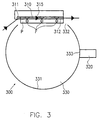
- FIG. 3 shows a third embodiment of a device 300 for the detection of a Fluorescent dye F shown in a sample P.
- This device differs from that shown in Fig. 1 in that instead of the glass plate 110 is a thin film waveguide provided on a substrate 315 310 is used, on the surface of which the sample P to be detected with the Fluorescent dye F is applied.
- 111 is used instead of the prism Grating coupler 311 for coupling the excitation light into the thin film waveguide 310 used.
- the device shown in FIG. 3 includes the same features as that in FIG Fig. 1 shown first embodiment. To avoid repetitions, in with respect to these components, therefore, only related to the description 1 with reference, it should be noted that the reference numerals of only differentiate corresponding components in their first digit.
- light that is the excitation wavelength contains, for example, monochromatic laser light
- fluorescent dye F which is in a on the waveguide applied sample P is contained by the evanescent field of excited laser radiation moving along the thin film waveguide 310.
- the fluorescent radiation emitted by the fluorescent dye F is finally transformed into a cavity 330 is blasted and detected there with a detector device 320.
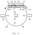
- FIG. 4 shows a fourth embodiment of a device 400 for the detection of a Fluorescent dye F shown in a sample P.
- Thin film waveguide 410 provided on a substrate 415 is used.
- the light to be used to excite the fluorescent dye also becomes coupled into the thin-film waveguide via a grating coupler 411.
- a coupling device 413 which is also preferred is provided in the form of a grating coupler.
- Analogous to the embodiment shown in FIG. 2 is also in this embodiment the outcoupled light led into a light trap 414 to an uncontrolled Avoid entry into the thin film waveguide.
Abstract
Description
- Fig. 1
- ein schematische Darstellung einer ersten Ausführungsform der vorliegenden Erfindung;
- Fig. 2
- eine schematische Darstellung einer zweiten Ausführungsform der vorliegenden Erfindung;
- Fig. 3
- eine schematische Darstellung einer dritten Ausführungsform der vorliegenden Erfindung; und
- Fig. 4
- eine schematische Darstellung einer vierten Ausführungsform der vorliegenden Erfindung.
Claims (24)
- Vorrichtung (100; 200; 300; 400) zum Nachweis eines Fluorenszenzfarbstoffs (F) in einer Probe (P), miteiner Einrichtung (110; 210; 310; 410) zum Anregen des nachzuweisenden Fluoreszenzfarbstoffs (F), die eine Lichteinkopplungseinrichtung (111; 211; 311; 411), durch welche Licht zum Anregen des Fluoreszenzfarbstoffs (F) in die Einrichtung (110; 210; 310; 410) einkoppelbar ist, und eine zum Aufbringen der Probe (P) vorgesehene Oberfläche (112; 212; 312; 412) aufweist, undeiner Einrichtung (120; 220; 320; 420) zum Detektieren von Fluoreszenzstrahlung, die durch den nachzuweisenden Fluoreszenzfarbstoff (F) emittiert worden ist,
gekennzeichnet durcheinen Hohlraum (130; 230; 330; 430), der eine hochreflektive innere Oberfläche (131; 231; 331; 431), eine erste, der Einrichtung (110; 210; 310; 410) zum Anregen des nachzuweisenden Fluoreszenzfarbstoffs (F) gegenüberliegende Öffnung (132; 232; 332; 432) und eine zweite, der Einrichtung (120; 220; 320; 420) zum Detektieren gegenüberliegende Öffnung (133; 233; 333; 433) aufweist. - Vorrichtung nach Anspruch 1, in welcher der Hohlraum (130; 230; 330; 430) im wesentlichen kugelförmig ausgebildet ist.
- Vorrichtung nach Anspruch 1 oder 2, in welcher die hochreflektive Oberfläche (131; 231; 331; 431) Bariumsulfat oder Spectralon umfaßt.
- Vorrichtung nach einem der vorangegangenen Ansprüche, in welcher wenigstens eine weitere Einrichtung (221, 222, ...; 421, 422, ...) zum Detektieren und eine entsprechende jeder weiteren Einrichtung zum Detektieren gegenüberliegende Öffnung (234, 235, ...; 434, 435, ...) in dem Hohlraum (230; 430) vorgesehen ist.
- Vorrichtung nach Anspruch 4, in welcher die wenigstens eine weitere Einrichtung (221, 222; 421, 422) zum Detektieren von Fluoreszenzstrahlung vorgesehen ist, welche durch den nachzuweisenden Fluoreszenzfarbstoff (F) emittiert worden ist und deren Wellenlänge sich von der Fluoreszenzstrahlung, die von der Einrichtung (220; 420) zum Detektieren nachzuweisen ist, unterscheidet.
- Vorrichtung nach Anspruch 4 oder 5, in welcher die wenigstens eine weitere Einrichtung (221, 222) zum Detektieren zum gleichzeitigen Nachweis wenigstens eines weiteren Fluorenszenzfarbstoffs (F') vorgesehen ist.
- Vorrichtung nach einem der vorangegangenen Ansprüche, in welcher jede Einrichtung (120; 220, 221, 222; 320; 420, 421, 422) zum Detektieren lichtdicht in der ihr entsprechenden zweiten Öffnung (133; 233, 234, 235; 333; 433, 434, 435) in dem Hohlraum (130; 230; 330; 430) vorgesehen ist.
- Vorrichtung nach einem der vorangegangenen Ansprüche, in welcherjede Einrichtung (120; 220, 221, 222; 320; 420, 421, 422) zum Detektieren eine Photomultipliereinrichtung aufweist.
- Vorrichtung nach Anspruch 8, in welcher jede Einrichtung (120; 220, 221, 222; 320; 420, 421, 422) zum Detektieren eine auf die Wellenlänge der von ihr nachzuweisende Fluoreszenzstrahlung abgestimmte Farbfiltereinrichtung aufweist.
- Vorrichtung nach einem der vorangegangenen Ansprüche, in welcher jede Einrichtung (120; 220, 221, 222; 320; 420, 421, 422) zum Detektieren eine Kollimationsoptik aufweist.
- Vorrichtung nach einem der vorangegangenen Ansprüche, in welchem vor der ersten Öffnung (231; 431) des Hohlraums (230; 430) eine Sperrfiltereinrichtung (240; 440), die für das zur Anregung verwendete Licht undurchlässig und für die zu detektierende Fluorenszenzstrahlung durchlässig ist, vorgesehen ist.
- Vorrichtung nach Anspruch 10, in welcher die Sperrfiltereinrichtung (240; 440) ein Interferenzfilter aufweist.
- Vorrichtung nach Anspruch 11 oder 12, in welcher die Sperrfiltereinrichtung (240; 440) gegenüber der Einrichtung zum Anregen des nachzuweisenden Fluoreszenzfarbstoffs bzw. der nachzuweisenden Fluoreszenzfarbstoffe geneigt ist.
- Vorrichtung nach einem der vorangegangenen Ansprüche, in welcher die Einrichtung zum Anregen des nachzuweisenden Fluoreszenzfarbstoffs bzw. der nachzuweisenden Fluoreszenzfarbstoffe eine Glasplatte (110; 210) aufweist.
- Vorrichtung nach Anspruch 14, in welcher die Glasplatte (110; 210) einen relativ hohen Brechungsindex, insbesondere von n >1,46, aufweist.
- Vorrichtung nach Anspruch 15, in welcher die Glasplatte (110; 210) Pyrexglas oder synthetisches Quarzglas umfaßt.
- Vorrichtung nach einem der Ansprüche 14 bis 16, in welcher die Lichteinkopplungseinrichtung in Form eines optisch dicht auf der Glasplatte aufliegenden Prismas (111; 211) oder in Form eines Gitterkopplers vorgesehen ist, und durch die Lichteinkopplungseinrichtung das Licht zur Anregung des nachzuweisenden Fluoreszenzfarbstoffs bzw. der nachzuweisenden Fluoreszenzfarbstoffe so in die Glasplatte (110; 210) eingekoppelt wird, daß es unter Totalreflexion durch dieselbe geleitet wird.
- Vorrichtung nach einem der Ansprüche 1 bis 13, in welcher die Einrichtung zum Anregen des nachzuweisenden Fluoreszenzfarbstoffs bzw. der nachzuweisenden Fluoreszenzfarbstoffe einen auf einem Substrat (315; 415) vorgesehenen Dünnfilm-Wellenleiter (310; 410) aufweist.
- Vorrichtung nach Anspruch 18, in welcher der Dünnfilm-Wellenleiter (310; 410) Ta2O5 umfaßt.
- Vorrichtung nach einem der Ansprüche 18 oder 19, in welcher die Lichteinkopplungseinrichtung einen Gitterkoppler (311; 411) aufweist, der das Licht zur Anregung des nachzuweisenden Fluoreszenzfarbstoffs bzw. der nachzuweisenden Fluoreszenzfarbstoffe so in den Dünnfilm-Wellenleiter (310; 410) eingekoppelt, daß es parallel zur Oberfläche des Dünnfilm-Wellenleiters (310; 410) durch denselben geleitet wird.
- Vorrichtung nach einem der vorangegangenen Ansprüche, in welcher eine Lichtauskopplungseinrichtung (213; 413) für das in die Einrichtung (210; 410) zum Anregen des nachzuweisenden Fluoreszenzfarbstoffs bzw. der nachzuweisenden Fluoreszenzfarbstoffe eingekoppelte Licht vorgesehen ist.
- Vorrichtung nach Anspruch 21 in Verbindung mit einem der Ansprüche 14 bis 17, in welcher die Lichtauskopplungseinrichtung durch einen Schliff (213) der der Lichteinkopplungseinrichtung (211) gegenüberliegenden Endfläche der Glasplatte (210), die vorgesehen ist.
- Vorrichtung nach Anspruch 21 in Verbindung mit einem der Ansprüche 18 bis 20, in welcher die Lichtauskopplungseinrichtung durch einen Gitterkoppler (413) im Bereich der Endfläche des Dünnfilm-Wellenleiters (410), die der Lichteinkopplungseinrichtung (411) gegenüberliegt, vorgesehen ist.
- Vorrichtung nach einem der Ansprüche 21 bis 23, in welcher eine Lichtfalle (214; 414) für das aus der Einrichtung (210; 410) zum Anregen des nachzuweisenden Fluoreszenzfarbstoffs bzw. der nachzuweisenden Fluoreszenzfarbstoffe ausgekoppelte Licht vorgesehen ist.
Applications Claiming Priority (2)
| Application Number | Priority Date | Filing Date | Title |
|---|---|---|---|
| DE19812681 | 1998-03-23 | ||
| DE1998112681 DE19812681A1 (de) | 1998-03-23 | 1998-03-23 | Vorrichtung zum Nachweis eines Fluoreszenzfarbstoffs |
Publications (2)
| Publication Number | Publication Date |
|---|---|
| EP0949502A2 true EP0949502A2 (de) | 1999-10-13 |
| EP0949502A3 EP0949502A3 (de) | 1999-12-29 |
Family
ID=7861968
Family Applications (1)
| Application Number | Title | Priority Date | Filing Date |
|---|---|---|---|
| EP98123363A Withdrawn EP0949502A3 (de) | 1998-03-23 | 1998-12-08 | Vorrichtung zum Nachweis eines Fluoreszenzfarbstoffs |
Country Status (2)
| Country | Link |
|---|---|
| EP (1) | EP0949502A3 (de) |
| DE (1) | DE19812681A1 (de) |
Cited By (1)
| Publication number | Priority date | Publication date | Assignee | Title |
|---|---|---|---|---|
| EP0947823A2 (de) * | 1998-04-03 | 1999-10-06 | Bodenseewerk Perkin-Elmer Gmbh | Vorrichtung zum Nachweis eines Fluoreszenzfarbstoffs |
Citations (7)
| Publication number | Priority date | Publication date | Assignee | Title |
|---|---|---|---|---|
| US4583860A (en) * | 1983-11-30 | 1986-04-22 | The United States Of America As Represented By The Administrator Of The National Aeronautics And Space Administration | Optical multiple sample vacuum integrating sphere |
| US4900923A (en) * | 1988-06-03 | 1990-02-13 | Carl-Zeiss-Stiftung | Reflectance measuring apparatus including a cylinder-shaped light conducting device between the measuring aperture and the specimen |
| US5315375A (en) * | 1992-02-11 | 1994-05-24 | Acrogen, Inc. | Sensitive light detection system |
| US5408312A (en) * | 1990-09-28 | 1995-04-18 | Kim Yoon-Ok | Device for the qualitative and/or quantitative determination of the composition of a sample that is to be analyzed |
| WO1996037761A1 (en) * | 1995-05-26 | 1996-11-28 | Lxr Biotechnology Inc. | Multi-channel acquisition using integrating sphere |
| US5633724A (en) * | 1995-08-29 | 1997-05-27 | Hewlett-Packard Company | Evanescent scanning of biochemical array |
| US5636015A (en) * | 1995-05-17 | 1997-06-03 | Minolta Co., Ltd. | Measuring apparatus for measuring an optical property of a fluorescent sample |
-
1998
- 1998-03-23 DE DE1998112681 patent/DE19812681A1/de not_active Withdrawn
- 1998-12-08 EP EP98123363A patent/EP0949502A3/de not_active Withdrawn
Patent Citations (7)
| Publication number | Priority date | Publication date | Assignee | Title |
|---|---|---|---|---|
| US4583860A (en) * | 1983-11-30 | 1986-04-22 | The United States Of America As Represented By The Administrator Of The National Aeronautics And Space Administration | Optical multiple sample vacuum integrating sphere |
| US4900923A (en) * | 1988-06-03 | 1990-02-13 | Carl-Zeiss-Stiftung | Reflectance measuring apparatus including a cylinder-shaped light conducting device between the measuring aperture and the specimen |
| US5408312A (en) * | 1990-09-28 | 1995-04-18 | Kim Yoon-Ok | Device for the qualitative and/or quantitative determination of the composition of a sample that is to be analyzed |
| US5315375A (en) * | 1992-02-11 | 1994-05-24 | Acrogen, Inc. | Sensitive light detection system |
| US5636015A (en) * | 1995-05-17 | 1997-06-03 | Minolta Co., Ltd. | Measuring apparatus for measuring an optical property of a fluorescent sample |
| WO1996037761A1 (en) * | 1995-05-26 | 1996-11-28 | Lxr Biotechnology Inc. | Multi-channel acquisition using integrating sphere |
| US5633724A (en) * | 1995-08-29 | 1997-05-27 | Hewlett-Packard Company | Evanescent scanning of biochemical array |
Cited By (1)
| Publication number | Priority date | Publication date | Assignee | Title |
|---|---|---|---|---|
| EP0947823A2 (de) * | 1998-04-03 | 1999-10-06 | Bodenseewerk Perkin-Elmer Gmbh | Vorrichtung zum Nachweis eines Fluoreszenzfarbstoffs |
Also Published As
| Publication number | Publication date |
|---|---|
| EP0949502A3 (de) | 1999-12-29 |
| DE19812681A1 (de) | 1999-09-30 |
Similar Documents
| Publication | Publication Date | Title |
|---|---|---|
| AT403745B (de) | Messanordnung mit einem für anregungs- und messstrahlung transparentem trägerelement | |
| DE69634963T2 (de) | Fluorometer | |
| DE3500247A1 (de) | Vorrichtung zum eliminieren der hintergrundstoerung bei fluoreszenzmessungen | |
| DE3414261A1 (de) | Interferenz-refraktometer | |
| DE102015101847B4 (de) | Strahlteiler und Anordnung zur Untersuchung einer mittels elektromagnetischer Strahlung anregbaren Probe | |
| DE3741940C2 (de) | Farbsensor | |
| EP0947823A2 (de) | Vorrichtung zum Nachweis eines Fluoreszenzfarbstoffs | |
| EP0174496A2 (de) | Verfahren zur Bestimmung der Strahlungswellenlänge und der wellenlängenkorrigierten Strahlungsleistung monochromatischer Lichtquellen, sowie Einrichtung zur Durchführung des Verfahrens | |
| EP0256280A2 (de) | Anordnung zur zeitlich aufgelösten optischen Rückstreumessung an Lichtwellenleitern | |
| DE102013224463B4 (de) | Vorrichtung zur Ermittlung von Fluoreszenzeigenschaften von Proben | |
| DE3214051A1 (de) | Spektralfluorometer | |
| DE19507119C2 (de) | Vorrichtung zur Bestimmung von Verunreinigungen | |
| DE102004049541A1 (de) | Meßsystem zur Vermessung von Oberflächen sowie Kalibrierverfahren hierfür | |
| DE2948590C2 (de) | Vorrichtung zur Absorptionsmessung von Gasgemischen | |
| DE3938142A1 (de) | Verfahren und vorrichtung zur qualitativen und quantitativen bestimmung von inhaltsstoffen | |
| DE69721910T2 (de) | Verfahren zur Kalibrierung eines spektroskopischen Gerätes | |
| EP0949502A2 (de) | Vorrichtung zum Nachweis eines Fluoreszenzfarbstoffs | |
| DE10042003B4 (de) | Materialprüfvorrichtung und deren Verwendung | |
| DD159567B1 (de) | Spektralfluorometer | |
| EP0950893A2 (de) | Vorrichtung zum Nachweis eines Fluoreszenzfarbstoffs | |
| DE19848120C2 (de) | Einrichtung zur Messung der Strahlungsabsorption von Gasen | |
| DE10033142C2 (de) | Erregerfilter für ein Endoskop zur Fluoreszenzuntersuchung | |
| EP0540715A1 (de) | Optischer sensor | |
| DE10131724B4 (de) | Optisches Absorptions-Messgerät | |
| DE19506192A1 (de) | Edelstein-Absorbtionsspektralphotometer |
Legal Events
| Date | Code | Title | Description |
|---|---|---|---|
| PUAI | Public reference made under article 153(3) epc to a published international application that has entered the european phase |
Free format text: ORIGINAL CODE: 0009012 |
|
| AK | Designated contracting states |
Kind code of ref document: A2 Designated state(s): DE FR GB IT |
|
| AX | Request for extension of the european patent |
Free format text: AL;LT;LV;MK;RO;SI |
|
| PUAL | Search report despatched |
Free format text: ORIGINAL CODE: 0009013 |
|
| AK | Designated contracting states |
Kind code of ref document: A3 Designated state(s): AT BE CH CY DE DK ES FI FR GB GR IE IT LI LU MC NL PT SE |
|
| AX | Request for extension of the european patent |
Free format text: AL;LT;LV;MK;RO;SI |
|
| RIC1 | Information provided on ipc code assigned before grant |
Free format text: 6G 01N 21/64 A, 6G 01N 21/55 B, 6G 01N 21/77 B |
|
| 17P | Request for examination filed |
Effective date: 20000221 |
|
| AKX | Designation fees paid |
Free format text: DE FR GB IT |
|
| 17Q | First examination report despatched |
Effective date: 20040510 |
|
| STAA | Information on the status of an ep patent application or granted ep patent |
Free format text: STATUS: THE APPLICATION IS DEEMED TO BE WITHDRAWN |
|
| 18D | Application deemed to be withdrawn |
Effective date: 20060601 |