EP0949377B1 - Continuous drying apparatus for porous web - Google Patents
Continuous drying apparatus for porous web Download PDFInfo
- Publication number
- EP0949377B1 EP0949377B1 EP99106155A EP99106155A EP0949377B1 EP 0949377 B1 EP0949377 B1 EP 0949377B1 EP 99106155 A EP99106155 A EP 99106155A EP 99106155 A EP99106155 A EP 99106155A EP 0949377 B1 EP0949377 B1 EP 0949377B1
- Authority
- EP
- European Patent Office
- Prior art keywords
- porous web
- heating cylinder
- drying
- cooling
- surface element
- Prior art date
- Legal status (The legal status is an assumption and is not a legal conclusion. Google has not performed a legal analysis and makes no representation as to the accuracy of the status listed.)
- Expired - Lifetime
Links
Images


Classifications
-
- D—TEXTILES; PAPER
- D21—PAPER-MAKING; PRODUCTION OF CELLULOSE
- D21F—PAPER-MAKING MACHINES; METHODS OF PRODUCING PAPER THEREON
- D21F5/00—Dryer section of machines for making continuous webs of paper
- D21F5/004—Drying webs by contact with heated surfaces or materials
-
- D—TEXTILES; PAPER
- D21—PAPER-MAKING; PRODUCTION OF CELLULOSE
- D21F—PAPER-MAKING MACHINES; METHODS OF PRODUCING PAPER THEREON
- D21F3/00—Press section of machines for making continuous webs of paper
- D21F3/02—Wet presses
- D21F3/0281—Wet presses in combination with a dryer roll
-
- D—TEXTILES; PAPER
- D21—PAPER-MAKING; PRODUCTION OF CELLULOSE
- D21F—PAPER-MAKING MACHINES; METHODS OF PRODUCING PAPER THEREON
- D21F5/00—Dryer section of machines for making continuous webs of paper
- D21F5/02—Drying on cylinders
Definitions
- the present invention relates to a continuous drying apparatus for porous web, according to the preamble of claim 1, suitable for use in a pressure drying apparatus applied to the dryer part of a paper machine, a pressure drying apparatus for porous web other than paper (e.g., a sheet drying apparatus), or the like.
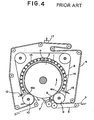
- Fig. 4 is a schematic diagram showing a conventional continuous drying apparatus according to the preamble of claim 1 for porous web as disclosed in US-A-4,461,095 (corresponding to Japanese Patent Publication No. HEI 1-56198).
- this apparatus as shown in Fig. 4, both porous web 3 (such as paper, a sheet or the like) to be dried and a drying band (e.g., a drying felt or wire) 4 for supporting this porous web 3 enter an air removing chamber 6 along with an auxiliary wire 5. After being subjected to an air removing process, they are passed through between two surface elements 1 and 8 having satisfactory. heat conductivity and air non-permeability.
- the above-mentioned surface elements 1 and 8 interpose the porous web 3 therebetween over the entire width.
- the surface element 1 in contact with the porous web 3 is heated by a heating medium in a heating space 2.
- the surface element 8 in contact with the drying band 4 is cooled by a liquid flowing through a cooling space 11.
- the porous web 3 is heated through the surface element 1, whereby the moisture contained in the porous web 3 vaporizes and turns into steam.
- the drying band 4 is cooled through the surface element 8
- the steam vaporized from the porous web 3 condenses into water within the drying band 4.
- the water (moisture) contained in the porous web 3 is gradually removed by external heating and cooling, so that the drying of the porous web 3 is continuously performed.
- the pressurized cooling water applies a pressure on the drying band 4.
- drying band 4 is separated from the surface elements 1 and 8, it is separated from the porous web 3 and the condensed water within the drying band 4 is removed at a suction box 17.
- cooling space 11 is sealed through appropriate seals 16a and 16b with respect to a hood 13 supported by support beams 14 and to rolls 9 and 10.
- the cooling liquid flowing through this cooling space 11 is supplied from a liquid supply port 12 and exhausted from a liquid exhaust port 15.
- the space between the hood 13 and various members, which constitute the cooling space 11, is sealed and the support beam 14 is increased in size due to pressure-proof structure, so there is also a problem that substantial time and labor will be required in replacing the surface element 8 or the drying band 4. More specifically, since the surface element 8 and the drying band 4 have endless structure, they must be slid and replaced in a direction perpendicular to the paper surface of Fig. 4.
- a closed space is formed upstream of the cooling space 11 serving as a drying section (more specifically, a range from the liquid supply port 12 to the liquid exhaust port 15).
- An air removing chamber 6 is provided in the closed space. With this, the air 7 in the closed chamber 6 is continuously exhausted with a suction pump, whereby an air removing process is performed.
- the pressure within the closed space has to be reduced to about 1 Torr or less. For this reason, there is also a problem that the exhausting speed of the suction pump will become too high.
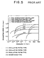
- an oil-sealed rotary vacuum pump or a mechanical booster pump is selected from the condition of the degree of vacuum. These characteristics are shown in Figs. 5 and 6, respectively.
- Fig. 7 shows the influence of air (noncondensable gases) on the condensation heat transfer rate of steam.
- air noncondensable gases
- a range that can neglect such an influence of air is air content rate ⁇ about 0.002 kg (air)/kg (steam).
- the range is also air content rate ⁇ about 0.001 m 3 (air)/m 3 (steam) in terms of a volume ratio.
- partial air pressure is equivalent to 1 Torr or less with respect to the total pressure 1000 Torr of atmospheric pressure.
- the present invention has been made in view of the problems mentioned with the continuous drying apparatus disclosed in US-A-4,461,095. Accordingly it is an object of the present invention to provide a continuous drying apparatus for porous web which is capable of drying porous web at higher efficiency.
- the continuous drying apparatus for porous web according to the present invention is constructed so as to have the following features.
- the continuous drying apparatus for porous web comprises a porous web for travelling on a drying line; a heating cylinder for contacting a surface of the porous web at its circumferential surface and rotating in synchronization with the travel of the porous web to heat the porous web; a drying band, permeable to air and water, for contacting and supporting a surface of the porous web which is not in contact with the heating cylinder and also for rotating in synchronization with the travel of the porous web; and a cooling surface element, impermeable to air and water, disposed on a surface of the drying band which is not in contact with the porous web.
- the continuous drying apparatus for porous web is provided with a pluralily of cooling water injection nozzles for cooling the cooling surface element disposed near the circumference of the heating cylinder on the side of the cooling surface element which is not in contact with the drying band; and with one or more pressure rotating bodies disposed near the circumference of the heating cylinder on the side of the cooling surface element which is not in contact with the drying band, and constructed of a rotating member and pressure means for pressurizing the rotating member toward the heating cylinder in such a way that the rotating member presses the cooling surface element, the drying band and the porous web against the circumferential surface of the heating cylinder.
- the drying band contacts and supports the porous web that travels on the drying line, and furthermore, the heating cylinder is pressurized by the pressure rotating body.
- a plurality of pressure rotating bodies may be provided according to need. With this, there is an advantage that a degree of contact between the porous web and the heating cylinder is improved to dry the porous web at higher efficiency.
- the drying band for contacting and supporting porous web may be constructed of a porous body.
- a hydraulic unit may be employed as the pressure means.
- the drying band is permeable to air and water, and a cooling surface element impermeable to air and water is disposed on a surface of the permeable drying band which is not in contact with the porous web.
- the cooling surface element can prevent the entry of external moisture without leaking the absorbed water therefrom.
- the permeable drying band and the cooling surface element may be constructed so as to be separable.
- the permeable drying band may make contact with a surface of the porous web which is not in contact with the heating cylinder, before the porous web makes contact with the heating cylinder.
- the cooling surface element may make contact with the permeable drying band at a predetermined position on the heating cylinder.
- an air-eliminating mechanism for eliminating air within both the permeable drying band and the porous web may be provided over the heating cylinder and upstream of the drying line beyond a position at which the porous web makes contact with the cooling surface element.
- the air-eliminating mechanism can absorb air in the porous web without reducing the pressure therein significantly, can also dry the air at higher efficiency, and can considerably reduce dissipation power required of this apparatus.
- a plurality of cooling water injection nozzles for cooling the drying band are disposed near the circumference of the heating cylinder on the side of the cooling surface element which is not in contact with the drying band.
- the cooling surface element is cooled by the cooling water injection nozzles, so there is an advantage that water within porous web can be efficiently absorbed.
- cooling units may be provided according to need. With this, so there is an advantage that cooling power is improved to absorb water within porous web at higher efficiency.
- the drying band may be constructed into a loop shape, and a dehydrator for removing water condensed within the drying band may be provided over a path along which the drying band rotates.
- the water in porous web, absorbed at the heating cylinder, can be removed with the dehydrator.
- the looped drying band can be continuously used.
- the above-mentioned continuous drying apparatus for porous web may further comprise a conveyor roll for conveying the cooling surface element.
- a slippage preventing process may be performed on a surface of the conveyor roll.
- a groove may be formed in the surface of the conveyor roll as the slippage preventing process.
- a plurality of heating-medium flow passages may be provided near an interior surface of the heating cylinder.
- an induction heating coil may be provided near an exterior surface of the heating cylinder.
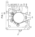
- Figs. 1 through 3 illustrate the construction of a continuous drying apparatus for porous web as an embodiment of the present invention.
- Fig. 1 is a schematic diagram showing the construction
- Fig. 2 a horizontal sectional diagram showing the essential part
- Fig. 3 a perspective diagram showing the essential part.
- the continuous drying apparatus for porous web (the concept of this porous web includes paper, hygroscopic sheet and the like), as illustrated in Fig. 1, has a plurality of pressure rotating bodies 115 installed over a heating cylinder (heating surface element) 101 and also has an air removing chamber (air-eliminating chamber) 110 provided upstream of these pressure rotating bodies 115 for removing air in porous web 102 which travels on a conveyor line (also referred to simply as a line) on the heating cylinder 101.
- a drying band (permeable drying band) 104 permeable to water and air is brought into contact with a surface of the porous web 102 traveling on the line on the heating cylinder 101, the surface being out of contact with the heating cylinder 101.
- a cooling surface element 105 impermeable to water and air is superposed on the drying band 104 and contacts and supports the drying band 104, thereby drying the porous web 102.
- the heating cylinder 101 contacts at its circumferential surface with the porous web 102, thereby heating the porous web 102.
- the heating cylinder 101 as shown in Fig. 2, is provided near the interior surface thereof with a plurality of heating-medium flow passages 1011 and is constructed into a hollow shape.
- a heating medium e.g., Therm S series produced by Shin-nittetu Kagaku Kabushiki Kaisha
- 1012 which is supplied and exhausted through rotary joints 1013, is passed through these heat-medium flow passages 1011, whereby the heating cylinder 101 is heated.
- the heating cylinder 101 is supported by bearings 1014 so that it can rotate.
- an induction heating coil 114 may be installed near the circumference of the heating cylinder 101 to heat the heating cylinder 101.
- the heating medium 1012 or the induction heating coil 114 may be installed for heating, or both of them may be installed to use either one as auxiliary heat.
- Advantageous methods can be freely selected according to the heating and other conditions.
- the drying band (permeable drying band) 104 contacts and supports the surface of the porous web 102 which is out of contact with the heating cylinder 101.
- the drying band 104 is constructed so as to be permeable to air and water (e.g., it employs porous material), and travels on an endless line that is conveyed by conveyor rolls (drying-band conveyor rolls) 103.
- the drying band 104 absorbs water within the porous web 102 while traveling on this endless line.
- the absorbed and collected water is removed by a suction box (dehydrator) 109 provided at a predetermined position over the endless belt.
- This suction box 109 dehydrates water contained in the drying band 104 by a vacuum pump, etc.
- this drying band 104 (measurement in a direction perpendicular to the line) is, for example, made wider than that of the porous web 102, as shown in Fig. 3. This is not only because the porous web 102 must be dried uniformly in the width direction thereof but also because the drying band 104, along with the porous web 102, sometimes meander to some degree during travel. Therefore, the width of this drying band 104 is thus made wider than that of the porous web 102 so that the porous web 102 can be reliably dried.
- the air removing chamber 110 is installed ahead of the position at which the porous web 102 makes contact with the cooling surface element 105, i.e., in a region (closed space) to which the drying band 104 on the heating cylinder 101 is exposed.
- This air removing chamber 110 eliminates air contained within both the drying band 104 and the porous web 102. More specifically, both the steam that is evaporated when the porous web 102 contacts with and is heated by the heating cylinder 101 and the air within the porous web 102 are absorbed by a suction pump (not shown) provided in this air removing chamber 110.
- this air removing chamber 110 equals the pressure within the suction box 109 positioned over the drying band 104, a water sealed pump, for example, is employed as the suction pump to suck air.
- the air removing chamber 110 is installed so as to have a narrower width than the width (measurement in the direction perpendicular to the line) of the cooling surface element 105 that travels on the line.
- water for cooling the cooling surface element 105 injected by cooling-water injection nozzles (cooling units) 118 to be described later, is prevented from entering this air removing chamber 110.
- the cooling surface element 105 contacts and supports the surface of the porous web 102 which is out of contact with the heating cylinder 101.
- the cooling surface element 105 is constructed so as to be impermeable to air and water and is traveled on the endless line by grooved conveyor rolls (grooved cooling-surface-element conveyor rolls) 106. And the cooling surface element 105 cools the porous web 102 being fed, while traveling on this endless line. Note that the grooved conveyor rolls 106 will be described later.
- the drying band 104 is brought into contact with the surface of the porous web 102 which is out of contact with the heating cylinder 101.
- this cooling surface element 105 is brought into contact at a predetermined position on the heating cylinder 101 (downstream side of the air removing chamber 110) with the surface of the drying band 104 which is out of contact with the porous web 102.
- this cooling surface element 105 In order to effectively push the porous web 102 which is dried against the heating cylinder 101, there is a need to process steam evaporated within the closed space enclosed by the heating cylinder 1 and the cooling surface element 105. If the porous web 102 is not cooled by this cooling surface element 105, then the pressure within this closed space will be raised by the pressure of steam evaporated from the porous web 102 and will exceed the pressure with which the cooling surface element 105 presses the porous web 102 against the heating cylinder 101. Also, if the pressure of steam within this closed space reaches saturation vapor pressure, water within the porous web 102 will no longer evaporate. In other words, in order to prevent this, a particular cooling surface such as the cooling surface element 105 is made, whereby steam within the porous web 102 is condensed and removed.
- the plurality of pressure rotating bodies 115 are disposed near the circumference of the heating cylinder 101 at predetermined intervals from the outside of the cooling surface element 105.
- the pressure rotating body 115 is constructed of a rotating member 107 for contacting and pressurizing the exterior surface of the cooling surface element 105, and a hydraulic cylinder (hydraulic unit as pressure means) 108 for pressurizing this rotating member 107 toward the heating cylinder 101 through a film of oil.
- the hydraulic cylinder 108 is provided with a pressure piston 113 that applies pressure to the rotating member 107.
- the pressure piston 113 is pushed by the pressure of oil supplied from an oil supply port 112 provided in the hydraulic cylinder 108, so that the rotating member 107 is pressurized.
- the cooling surface element 105 can be pressurized with arbitrary pressure developed by the hydraulic cylinder 108.
- part of the oil supplied from the oil supply port 112 is also supplied to the pressure space 117 between the rotating member 107 and the pressure piston 113, and a film of oil is formed within the pressure space 117.
- the pressure piston 113 pressurizes the rotating member 107 toward the heating cylinder 101 through a film of oil within the pressure space 117 instead of directly pressurizing the rotating member 107.
- the rotating member 107 is free to rotate although being pressurized by the pressure piston 113.
- the rotating member 107 is prevented from resisting the traveling of the cooling surface element 105 when contacting and pushing the cooling surface element 105.
- the pressure rotating body 115 is equipped with drive means (e.g., a hydraulic unit, a motor, etc.(not shown)). With this drive means, the pressure rotating body 115 is movable toward and away from the heating cylinder 101 in the radial direction of the heating cylinder 101. With this, the exchange of the cooling surface element 105 or the drying band 104 can be readily performed by moving the pressure rotating body 115 away from the heating cylinder 101 in the radial direction.
- drive means e.g., a hydraulic unit, a motor, etc.(not shown)
- cooling-water injection nozzles (cooling units) 118 are disposed near the circumference of the heating cylinder 101 along with the pressure rotating bodies 115. These cooling-water injection nozzles 118 are used to inject cooling water for cooling the cooling surface element 105. Between the pressure rotating bodies 115, the cooling-water injection nozzles 118 are disposed at appropriate intervals so that the entire cooling surface element 105 can be uniformly cooled. Furthermore, the cooling water that is injected from the cooling-water injection nozzle 118 is used not only for cooling the cooling surface element 105 but also for reducing the friction between the rotating member 107 and the cooling surface element 105. Note that this cooling water is collected and recirculated.
- the cooling surface element 105 incidentally, is conveyed by the grooved conveyor rolls 106, as described above.
- the groove (not shown) formed in the surface of this grooved conveyor roll 106 is provided for a slippage preventing process.
- the groove is formed in the surface of the roll, so water injected from the cooling-water injection nozzle 118 can enter this groove. And the water that entered this groove is flung away by centrifugal force, or adheres to the cooling surface element 105 and is exhausted.
- the groove in the roll surface can be formed in various forms. For instance, the groove can extend in the direction along the circumferential surface of the roll or in the direction crossing this direction.
- the roll surface is not limited to a groove such as this, but may be simply roughened. Even in this case, water can be easily exhausted. Furthermore, not only does the exhaust of water become easy by forming a groove or roughening a surface, but the friction of the roll surface relative to the cooling surface element 105 can also be made great. As a result, the effect of slippage prevention can be further enhanced.
- the continuous drying apparatus for porous web in the continuous drying apparatus for porous web according to an embodiment, as shown in Fig. 1, before the porous web 102 that is dried makes contact with the heating cylinder 101, the surface of the porous web 102 which is out of .contact with the heating cylinder 101 is contacted by the drying band 104. After the porous web 102 in contact with this drying band 104 comes into contact with the heating cylinder 101, it is heated by the heating cylinder 101.
- the porous web 102 is heated, so that the water within the porous web 102 evaporates with steam pressure greater than atmospheric pressure. At this time, air is expelled out of the porous web 102. Then, air (air within the drying band 104, steam within the air removing chamber 102, etc.) is sucked by the air removing chamber 110.
- the surface of the drying band 104 which is out of contact with the porous web 102 is contacted at the heating cylinder 101 downstream of the air removing chamber 110 by the cooling surface element 105.
- the porous web 102 from which the interior air has been sucked by the air removing chamber 110 is conveyed on the heating cylinder 101.
- water within the porous web 102 evaporates and turns into steam by the heating of the heating cylinder 101. That is, the water is reiteratedly subjected to the pressure of the pressure rotating bodies 115 and the cooling of the cooling water from the cooling-water injection nozzle 118, so that the water is condensed within the drying band 104 and is adsorbed and conveyed by the drying band 104. Note that this adsorbed water is removed by the suction box 109 over the conveyor line of the drying band 104.
- the porous web 102 traveling on the conveyor line on the heating cylinder 101 is pressed against the heating cylinder 101 by the plurality of pressure rotating bodies 115.
- the cooling surface element 105 is effectively pressed under arbitrary pressure, whereby the porous web 102 can be dried.
- the pressure rotating body 115 is movable toward and away from the heating cylinder 101, there is an advantage that exchange of the drying band 104 and the cooling surface element 105 can be readily performed.
- drying band 104 that contacts and supports the porous web 102 consists of a porous body, there is an advantage that the drying band 104 can efficiently absorb water evaporated from the porous web 102.
- cooling surface element 105 is disposed on the surface of the drying band 104 which is out of contact with the porous web 102, there is an advantage that the cooling surface element 105 can prevent the entry of external moisture without leaking the absorbed water therefrom.
- the air removing chamber 110 is provided over the heating cylinder 101 in front of the position at which the cooling surface element 105 is brought into contact with the drying band 4 and also heats the porous web 102 which is in contact with the drying band 104, so there is an advantage that the air removing chamber 110 can absorb air in the porous web 102 without reducing the pressure therein significantly, can also dry the air at higher efficiency, and can considerably reduce dissipation power required of this apparatus.
- the drying band 104 can efficiently absorb water within the porous web 102.
- drying band 104 travels between the heating cylinder 101 and the suction box 109 so that the water in porous web 101, absorbed at the heating cylinder 101, can be removed with the suction box 109.
- the looped drying band 104 can be continuously used.
Landscapes
- Drying Of Solid Materials (AREA)
- Treatment Of Fiber Materials (AREA)
- Paper (AREA)
Applications Claiming Priority (2)
| Application Number | Priority Date | Filing Date | Title |
|---|---|---|---|
| JP10099209A JPH11293583A (ja) | 1998-04-10 | 1998-04-10 | 多孔質ウェブの連続乾燥装置 |
| JP9920998 | 1998-04-10 |
Publications (3)
| Publication Number | Publication Date |
|---|---|
| EP0949377A2 EP0949377A2 (en) | 1999-10-13 |
| EP0949377A3 EP0949377A3 (en) | 2000-05-24 |
| EP0949377B1 true EP0949377B1 (en) | 2004-06-30 |
Family
ID=14241272
Family Applications (1)
| Application Number | Title | Priority Date | Filing Date |
|---|---|---|---|
| EP99106155A Expired - Lifetime EP0949377B1 (en) | 1998-04-10 | 1999-04-07 | Continuous drying apparatus for porous web |
Country Status (8)
| Country | Link |
|---|---|
| US (1) | US6161301A (zh) |
| EP (1) | EP0949377B1 (zh) |
| JP (1) | JPH11293583A (zh) |
| KR (1) | KR100309054B1 (zh) |
| CN (1) | CN1097657C (zh) |
| CA (1) | CA2264376C (zh) |
| DE (1) | DE69918351T2 (zh) |
| ID (1) | ID22411A (zh) |
Families Citing this family (11)
| Publication number | Priority date | Publication date | Assignee | Title |
|---|---|---|---|---|
| DE102004017809A1 (de) | 2004-04-13 | 2005-10-27 | Voith Paper Patent Gmbh | Trockenanordnung |
| DE102005000782A1 (de) * | 2005-01-05 | 2006-07-20 | Voith Paper Patent Gmbh | Trockenzylinder |
| JP4105209B2 (ja) * | 2005-07-26 | 2008-06-25 | 三菱電機株式会社 | 手乾燥装置 |
| CN100531640C (zh) * | 2005-08-18 | 2009-08-26 | 三菱电机株式会社 | 手干燥装置 |
| JP4901395B2 (ja) * | 2006-09-26 | 2012-03-21 | 富士フイルム株式会社 | 塗布膜の乾燥方法 |
| DE102008043916A1 (de) | 2008-11-20 | 2010-05-27 | Voith Patent Gmbh | Trockenanordnung mit Druckkompensationseinrichtung |
| DE102008043918A1 (de) | 2008-11-20 | 2010-05-27 | Voith Patent Gmbh | Trockenanordnung mit äußerer und innerer Druckhaube |
| US20140101959A1 (en) * | 2012-10-11 | 2014-04-17 | Alan Richard Priebe | Dryer impinging heating liquid onto barrier |
| US8756830B2 (en) * | 2012-10-11 | 2014-06-24 | Eastman Kodak Company | Dryer transporting moistened medium through heating liquid |
| CN106322974B (zh) * | 2015-06-17 | 2020-04-24 | 金红叶纸业集团有限公司 | 一种烘缸装置及其运行方法 |
| KR101974895B1 (ko) * | 2018-10-04 | 2019-05-07 | 강원대학교산학협력단 | 압착 가열 기상 그라프팅 소수화 장치 및 이를 이용하여 제조한 내열수성 종이 및 유흡착 종이 |
Family Cites Families (15)
| Publication number | Priority date | Publication date | Assignee | Title |
|---|---|---|---|---|
| US3118743A (en) * | 1959-04-15 | 1964-01-21 | Kimberly Clark Co | Papermaking drier drum |
| US3116985A (en) * | 1960-07-26 | 1964-01-07 | Kimberly Clark Co | Papermaking drying drum |
| US3110612A (en) * | 1960-12-20 | 1963-11-12 | Albemarle Paper Mfg Company | Method and apparatus for cast coating paper |
| FI61537C (fi) * | 1981-02-19 | 1982-08-10 | Tampella Oy Ab | Foerfarande och anlaeggning foer kontinuerlig torkning av en pappers- eller liknande poroes bana |
| ES524248A0 (es) * | 1982-07-22 | 1984-06-16 | Wiggins Teape Group Ltd | "un procedimiento para producir papel que tenga por lo menos porciones contranslucidez mejorada" |
| DE3319241A1 (de) * | 1983-04-30 | 1984-11-15 | Thomas Josef Heimbach GmbH & Co, 5160 Düren | Verfahren zum herstellen eines endlosen schlauchfilzes sowie vorrichtung zum durchfuehren dieses verfahrens |
| US4738752A (en) * | 1986-08-12 | 1988-04-19 | Beloit Corporation | Heated extended nip press apparatus |
| IT1198207B (it) * | 1986-11-28 | 1988-12-21 | Sperotto Rimar Spa | Essicatoio a percussione ed asprazione d'aria per macchine di trattamento tessile in continuo |
| JPS6456198A (en) * | 1987-08-26 | 1989-03-03 | Tokyo Kyuei Kk | Self-maturing method in biological filter tank |
| ES2011381A6 (es) * | 1988-08-17 | 1990-01-01 | Garcia Pastor Daniel | Proceso mecanico de secado aplicable a la fabricacion de papel. |
| FI82274C (fi) * | 1989-03-30 | 1991-02-11 | Valmet Paper Machinery Inc | Foerfarande foer varmpressning och torkningsanordning. |
| US5060396A (en) * | 1989-08-17 | 1991-10-29 | W. R. Grace & Co.-Conn. | Zoned cylindrical dryer |
| US5121560A (en) * | 1990-12-19 | 1992-06-16 | Advance Systems, Inc. | Apparatus and method for cooling a printed web |
| DE4301750C2 (de) * | 1993-01-23 | 1996-10-10 | Voith Gmbh J M | Verfahren und Vorrichtung zum Entwässern einer Bahn mittels Pressen |
| FI955014A (fi) * | 1995-10-20 | 1997-04-21 | Valmet Corp | Paperikoneen puristinosa, jossa käytetään pitkänippipuristinta |
-
1998
- 1998-04-10 JP JP10099209A patent/JPH11293583A/ja not_active Withdrawn
- 1998-11-04 KR KR1019980047172A patent/KR100309054B1/ko not_active IP Right Cessation
-
1999
- 1999-03-03 CA CA002264376A patent/CA2264376C/en not_active Expired - Fee Related
- 1999-03-10 US US09/265,398 patent/US6161301A/en not_active Expired - Fee Related
- 1999-03-16 CN CN99104020A patent/CN1097657C/zh not_active Expired - Fee Related
- 1999-03-17 ID IDP990232D patent/ID22411A/id unknown
- 1999-04-07 DE DE69918351T patent/DE69918351T2/de not_active Expired - Fee Related
- 1999-04-07 EP EP99106155A patent/EP0949377B1/en not_active Expired - Lifetime
Also Published As
| Publication number | Publication date |
|---|---|
| KR100309054B1 (ko) | 2001-12-28 |
| DE69918351T2 (de) | 2005-07-14 |
| CA2264376C (en) | 2002-04-16 |
| EP0949377A2 (en) | 1999-10-13 |
| EP0949377A3 (en) | 2000-05-24 |
| CN1232104A (zh) | 1999-10-20 |
| ID22411A (id) | 1999-10-14 |
| US6161301A (en) | 2000-12-19 |
| DE69918351D1 (de) | 2004-08-05 |
| CA2264376A1 (en) | 1999-10-10 |
| JPH11293583A (ja) | 1999-10-26 |
| CN1097657C (zh) | 2003-01-01 |
| KR19990081779A (ko) | 1999-11-15 |
Similar Documents
| Publication | Publication Date | Title |
|---|---|---|
| EP0949377B1 (en) | Continuous drying apparatus for porous web | |
| FI87669C (fi) | Foerfarande och tork vid torkning av papper | |
| FI69141C (fi) | Foerfarande och anordning foer torkning av en pappersbana eller liknande | |
| KR100412118B1 (ko) | 섬유웹의건조장치및제지기의건조장치 | |
| US3296710A (en) | Absorbent dryer | |
| FI80102C (fi) | Foerfarande och anordning foer torkning av en fiberbana. | |
| US3753298A (en) | Web dryer | |
| JPS6360159B2 (zh) | ||
| FI110815B (fi) | Laite lämmitetyn ja reagoivan jatkuvan materiaalirainan linjalla tapahtuvaa käsittelyä varten | |
| KR900702134A (ko) | 단일층 드라이어 섹션 장치 및 웨브의 건조 방법 | |
| US6294050B1 (en) | Drying end of a machine for the production of a material web and method of drying a material web | |
| JPS59137595A (ja) | 紙又は板紙用ドライヤ | |
| US4485567A (en) | Dryer felt run | |
| US5706587A (en) | Apparatus for drying a fibre web | |
| US6076275A (en) | Continuous drying apparatus for porous web | |
| CZ20013723A3 (cs) | Kondicionovační zařízení pro změnu obsahu vlhkosti tiskových a jiných materiálů, zejména papírových , a způsob jeho činnosti | |
| JP2002509998A (ja) | 繊維ウェブ乾燥方法および装置 | |
| US5966834A (en) | Machine and method for producing a material web | |
| US5636452A (en) | Paper drying machine and method for drying a paper web in a paper drying machine | |
| US5299363A (en) | Dryer group web transfer region for paper making machine | |
| FI81625B (fi) | Anordning foer torkning av en fiberbana. | |
| US4800656A (en) | Device and process for drying solvent-containing plastic sheets or films | |
| JP3122018B2 (ja) | 紙ウェブを湿す方法および装置 | |
| FI59636C (fi) | Torkanlaeggning foer torkning av en pappers- kartong-eller textilbana eller annan fibrig eller poroes bana | |
| JP2001503111A (ja) | 繊維ウェブ乾燥装置 |
Legal Events
| Date | Code | Title | Description |
|---|---|---|---|
| PUAI | Public reference made under article 153(3) epc to a published international application that has entered the european phase |
Free format text: ORIGINAL CODE: 0009012 |
|
| AK | Designated contracting states |
Kind code of ref document: A2 Designated state(s): DE FI IT SE |
|
| AX | Request for extension of the european patent |
Free format text: AL;LT;LV;MK;RO;SI |
|
| PUAL | Search report despatched |
Free format text: ORIGINAL CODE: 0009013 |
|
| AK | Designated contracting states |
Kind code of ref document: A3 Designated state(s): AT BE CH CY DE DK ES FI FR GB GR IE IT LI LU MC NL PT SE |
|
| AX | Request for extension of the european patent |
Free format text: AL;LT;LV;MK;RO;SI |
|
| RIC1 | Information provided on ipc code assigned before grant |
Free format text: 7D 21F 5/02 A, 7D 21F 3/02 B |
|
| 17P | Request for examination filed |
Effective date: 20000529 |
|
| AKX | Designation fees paid |
Free format text: DE FI IT SE |
|
| 17Q | First examination report despatched |
Effective date: 20021220 |
|
| GRAP | Despatch of communication of intention to grant a patent |
Free format text: ORIGINAL CODE: EPIDOSNIGR1 |
|
| RIN1 | Information on inventor provided before grant (corrected) |
Inventor name: SUZUKI, SETSUO Inventor name: SANADA, AKIRA,C/O MITSUBISHI HEAVY IND., LTD. Inventor name: HOSHI, YOUNOSUKE,C/O MITSUBISHI HEAVY IND., LTD. |
|
| GRAS | Grant fee paid |
Free format text: ORIGINAL CODE: EPIDOSNIGR3 |
|
| GRAA | (expected) grant |
Free format text: ORIGINAL CODE: 0009210 |
|
| AK | Designated contracting states |
Kind code of ref document: B1 Designated state(s): DE FI IT SE |
|
| RIN1 | Information on inventor provided before grant (corrected) |
Inventor name: SUZUKI, SETSUO Inventor name: SANADA, AKIRA,C/O MITSUBISHI HEAVY IND., LTD. Inventor name: HOSHI, YOUNOSUKE,C/O MITSUBISHI HEAVY IND., LTD. |
|
| REG | Reference to a national code |
Ref country code: SE Ref legal event code: TRGR |
|
| REF | Corresponds to: |
Ref document number: 69918351 Country of ref document: DE Date of ref document: 20040805 Kind code of ref document: P |
|
| PGFP | Annual fee paid to national office [announced via postgrant information from national office to epo] |
Ref country code: DE Payment date: 20050331 Year of fee payment: 7 |
|
| PGFP | Annual fee paid to national office [announced via postgrant information from national office to epo] |
Ref country code: SE Payment date: 20050406 Year of fee payment: 7 |
|
| PGFP | Annual fee paid to national office [announced via postgrant information from national office to epo] |
Ref country code: FI Payment date: 20050414 Year of fee payment: 7 |
|
| PLBE | No opposition filed within time limit |
Free format text: ORIGINAL CODE: 0009261 |
|
| STAA | Information on the status of an ep patent application or granted ep patent |
Free format text: STATUS: NO OPPOSITION FILED WITHIN TIME LIMIT |
|
| 26N | No opposition filed |
Effective date: 20050331 |
|
| PG25 | Lapsed in a contracting state [announced via postgrant information from national office to epo] |
Ref country code: FI Free format text: LAPSE BECAUSE OF NON-PAYMENT OF DUE FEES Effective date: 20060407 |
|
| PG25 | Lapsed in a contracting state [announced via postgrant information from national office to epo] |
Ref country code: SE Free format text: LAPSE BECAUSE OF NON-PAYMENT OF DUE FEES Effective date: 20060408 |
|
| PGFP | Annual fee paid to national office [announced via postgrant information from national office to epo] |
Ref country code: IT Payment date: 20060430 Year of fee payment: 8 |
|
| PG25 | Lapsed in a contracting state [announced via postgrant information from national office to epo] |
Ref country code: DE Free format text: LAPSE BECAUSE OF NON-PAYMENT OF DUE FEES Effective date: 20061101 |
|
| EUG | Se: european patent has lapsed | ||
| PG25 | Lapsed in a contracting state [announced via postgrant information from national office to epo] |
Ref country code: IT Free format text: LAPSE BECAUSE OF NON-PAYMENT OF DUE FEES Effective date: 20070407 |