EP0949079A1 - Herstellungsverfahren für einen Tintenstrahldruckkopf - Google Patents
Herstellungsverfahren für einen Tintenstrahldruckkopf Download PDFInfo
- Publication number
- EP0949079A1 EP0949079A1 EP99105199A EP99105199A EP0949079A1 EP 0949079 A1 EP0949079 A1 EP 0949079A1 EP 99105199 A EP99105199 A EP 99105199A EP 99105199 A EP99105199 A EP 99105199A EP 0949079 A1 EP0949079 A1 EP 0949079A1
- Authority
- EP
- European Patent Office
- Prior art keywords
- substrate
- forming
- pressure chambers
- etching
- passageways
- Prior art date
- Legal status (The legal status is an assumption and is not a legal conclusion. Google has not performed a legal analysis and makes no representation as to the accuracy of the status listed.)
- Withdrawn
Links
Images


Classifications
-
- B—PERFORMING OPERATIONS; TRANSPORTING
- B41—PRINTING; LINING MACHINES; TYPEWRITERS; STAMPS
- B41J—TYPEWRITERS; SELECTIVE PRINTING MECHANISMS, i.e. MECHANISMS PRINTING OTHERWISE THAN FROM A FORME; CORRECTION OF TYPOGRAPHICAL ERRORS
- B41J2/00—Typewriters or selective printing mechanisms characterised by the printing or marking process for which they are designed
- B41J2/005—Typewriters or selective printing mechanisms characterised by the printing or marking process for which they are designed characterised by bringing liquid or particles selectively into contact with a printing material
- B41J2/01—Ink jet
- B41J2/135—Nozzles
- B41J2/16—Production of nozzles
- B41J2/1621—Manufacturing processes
- B41J2/1626—Manufacturing processes etching
-
- B—PERFORMING OPERATIONS; TRANSPORTING
- B41—PRINTING; LINING MACHINES; TYPEWRITERS; STAMPS
- B41J—TYPEWRITERS; SELECTIVE PRINTING MECHANISMS, i.e. MECHANISMS PRINTING OTHERWISE THAN FROM A FORME; CORRECTION OF TYPOGRAPHICAL ERRORS
- B41J2/00—Typewriters or selective printing mechanisms characterised by the printing or marking process for which they are designed
- B41J2/005—Typewriters or selective printing mechanisms characterised by the printing or marking process for which they are designed characterised by bringing liquid or particles selectively into contact with a printing material
- B41J2/01—Ink jet
- B41J2/135—Nozzles
- B41J2/16—Production of nozzles
- B41J2/1607—Production of print heads with piezoelectric elements
- B41J2/161—Production of print heads with piezoelectric elements of film type, deformed by bending and disposed on a diaphragm
-
- B—PERFORMING OPERATIONS; TRANSPORTING
- B41—PRINTING; LINING MACHINES; TYPEWRITERS; STAMPS
- B41J—TYPEWRITERS; SELECTIVE PRINTING MECHANISMS, i.e. MECHANISMS PRINTING OTHERWISE THAN FROM A FORME; CORRECTION OF TYPOGRAPHICAL ERRORS
- B41J2/00—Typewriters or selective printing mechanisms characterised by the printing or marking process for which they are designed
- B41J2/005—Typewriters or selective printing mechanisms characterised by the printing or marking process for which they are designed characterised by bringing liquid or particles selectively into contact with a printing material
- B41J2/01—Ink jet
- B41J2/135—Nozzles
- B41J2/16—Production of nozzles
- B41J2/1621—Manufacturing processes
- B41J2/1631—Manufacturing processes photolithography
-
- B—PERFORMING OPERATIONS; TRANSPORTING
- B41—PRINTING; LINING MACHINES; TYPEWRITERS; STAMPS
- B41J—TYPEWRITERS; SELECTIVE PRINTING MECHANISMS, i.e. MECHANISMS PRINTING OTHERWISE THAN FROM A FORME; CORRECTION OF TYPOGRAPHICAL ERRORS
- B41J2/00—Typewriters or selective printing mechanisms characterised by the printing or marking process for which they are designed
- B41J2/005—Typewriters or selective printing mechanisms characterised by the printing or marking process for which they are designed characterised by bringing liquid or particles selectively into contact with a printing material
- B41J2/01—Ink jet
- B41J2/135—Nozzles
- B41J2/16—Production of nozzles
- B41J2/1621—Manufacturing processes
- B41J2/1632—Manufacturing processes machining
-
- B—PERFORMING OPERATIONS; TRANSPORTING
- B41—PRINTING; LINING MACHINES; TYPEWRITERS; STAMPS
- B41J—TYPEWRITERS; SELECTIVE PRINTING MECHANISMS, i.e. MECHANISMS PRINTING OTHERWISE THAN FROM A FORME; CORRECTION OF TYPOGRAPHICAL ERRORS
- B41J2/00—Typewriters or selective printing mechanisms characterised by the printing or marking process for which they are designed
- B41J2/005—Typewriters or selective printing mechanisms characterised by the printing or marking process for which they are designed characterised by bringing liquid or particles selectively into contact with a printing material
- B41J2/01—Ink jet
- B41J2/135—Nozzles
- B41J2/16—Production of nozzles
- B41J2/1621—Manufacturing processes
- B41J2/1637—Manufacturing processes molding
-
- C—CHEMISTRY; METALLURGY
- C03—GLASS; MINERAL OR SLAG WOOL
- C03C—CHEMICAL COMPOSITION OF GLASSES, GLAZES OR VITREOUS ENAMELS; SURFACE TREATMENT OF GLASS; SURFACE TREATMENT OF FIBRES OR FILAMENTS MADE FROM GLASS, MINERALS OR SLAGS; JOINING GLASS TO GLASS OR OTHER MATERIALS
- C03C15/00—Surface treatment of glass, not in the form of fibres or filaments, by etching
-
- B—PERFORMING OPERATIONS; TRANSPORTING
- B41—PRINTING; LINING MACHINES; TYPEWRITERS; STAMPS
- B41J—TYPEWRITERS; SELECTIVE PRINTING MECHANISMS, i.e. MECHANISMS PRINTING OTHERWISE THAN FROM A FORME; CORRECTION OF TYPOGRAPHICAL ERRORS
- B41J2/00—Typewriters or selective printing mechanisms characterised by the printing or marking process for which they are designed
- B41J2/005—Typewriters or selective printing mechanisms characterised by the printing or marking process for which they are designed characterised by bringing liquid or particles selectively into contact with a printing material
- B41J2/01—Ink jet
- B41J2/135—Nozzles
- B41J2/14—Structure thereof only for on-demand ink jet heads
- B41J2002/14387—Front shooter
-
- B—PERFORMING OPERATIONS; TRANSPORTING
- B41—PRINTING; LINING MACHINES; TYPEWRITERS; STAMPS
- B41J—TYPEWRITERS; SELECTIVE PRINTING MECHANISMS, i.e. MECHANISMS PRINTING OTHERWISE THAN FROM A FORME; CORRECTION OF TYPOGRAPHICAL ERRORS
- B41J2/00—Typewriters or selective printing mechanisms characterised by the printing or marking process for which they are designed
- B41J2/005—Typewriters or selective printing mechanisms characterised by the printing or marking process for which they are designed characterised by bringing liquid or particles selectively into contact with a printing material
- B41J2/01—Ink jet
- B41J2/135—Nozzles
- B41J2/14—Structure thereof only for on-demand ink jet heads
- B41J2002/14411—Groove in the nozzle plate
-
- B—PERFORMING OPERATIONS; TRANSPORTING
- B41—PRINTING; LINING MACHINES; TYPEWRITERS; STAMPS
- B41J—TYPEWRITERS; SELECTIVE PRINTING MECHANISMS, i.e. MECHANISMS PRINTING OTHERWISE THAN FROM A FORME; CORRECTION OF TYPOGRAPHICAL ERRORS
- B41J2/00—Typewriters or selective printing mechanisms characterised by the printing or marking process for which they are designed
- B41J2/005—Typewriters or selective printing mechanisms characterised by the printing or marking process for which they are designed characterised by bringing liquid or particles selectively into contact with a printing material
- B41J2/01—Ink jet
- B41J2/135—Nozzles
- B41J2/14—Structure thereof only for on-demand ink jet heads
- B41J2002/14419—Manifold
-
- Y—GENERAL TAGGING OF NEW TECHNOLOGICAL DEVELOPMENTS; GENERAL TAGGING OF CROSS-SECTIONAL TECHNOLOGIES SPANNING OVER SEVERAL SECTIONS OF THE IPC; TECHNICAL SUBJECTS COVERED BY FORMER USPC CROSS-REFERENCE ART COLLECTIONS [XRACs] AND DIGESTS
- Y10—TECHNICAL SUBJECTS COVERED BY FORMER USPC
- Y10T—TECHNICAL SUBJECTS COVERED BY FORMER US CLASSIFICATION
- Y10T29/00—Metal working
- Y10T29/49—Method of mechanical manufacture
- Y10T29/49002—Electrical device making
- Y10T29/49117—Conductor or circuit manufacturing
- Y10T29/49124—On flat or curved insulated base, e.g., printed circuit, etc.
- Y10T29/49126—Assembling bases
-
- Y—GENERAL TAGGING OF NEW TECHNOLOGICAL DEVELOPMENTS; GENERAL TAGGING OF CROSS-SECTIONAL TECHNOLOGIES SPANNING OVER SEVERAL SECTIONS OF THE IPC; TECHNICAL SUBJECTS COVERED BY FORMER USPC CROSS-REFERENCE ART COLLECTIONS [XRACs] AND DIGESTS
- Y10—TECHNICAL SUBJECTS COVERED BY FORMER USPC
- Y10T—TECHNICAL SUBJECTS COVERED BY FORMER US CLASSIFICATION
- Y10T29/00—Metal working
- Y10T29/49—Method of mechanical manufacture
- Y10T29/49401—Fluid pattern dispersing device making, e.g., ink jet
Definitions
- the present invention relates to an ink jet head for an ink jet printer and more particularly to an ink jet head configured to distribute ink from a single ink pool to a plurality of pressure chambers via respective passageways and a method of producing the same.
- an ink jet head for in an ink jet printer includes three-dimensional ink passageways extending from a single ink pool to nozzles and pressure chambers densely arranged at a preselected pitch. It has been customary to form the ink passageways by positioning and stacking a plurality of substrates formed with grooves and holes and then adhering them together.
- Japanese Patent Laid-Open Publication Nos. 7-156398 (Prior Art 1 hereinafter) and 7-246701 (Prior Art 2 hereinafter) each discloses a particular ink jet head
- Prior Art 1 The problem with Prior Art 1 is as follows. Unless positional deviation apt to occur during the stacking of substrates, irregularity in positional accuracy and deformation ascribable to baking are strictly controlled, walls, particularly those adjoining nozzles, are stepped and effect the ejection characteristic relating to ink drops, Specifically, the stepped walls cause each of the nozzles to eject an ink drop at a different speed, renders the size of ink drops irregular, and disturbs the frequency to follow.
- Prior Art 2 has a problem that the substrates are dislocated relative to each other. This, coupled with the fact that adhesive bulges out from the substrates and fails to fully adhere the substrates, causes the walls of nozzles to be stepped, also resulting in low yield and high cost.
- an ink pool forming substrate and a feed hole forming substrate may be formed of metal while a pressure chamber forming substrate may be formed of ceramics. This, however, increases the number of parts constituting the head.
- a method of producing an ink jet head of the present invention is applicable to an ink jet head of the type including substrate formed with an ink pool in one major surfacc thereof, a plurality of pressure chambers in the other major surface thereof, a plurality of feed holes respectively extending from the ink pool to the pressure chambers, and a plurality of through passageways respectively extending from the pressure chambers throughout the substrate.
- the methods includes the steps of etching a single photosensitive glass ceramics substrate to thereby form the pressure chambers, feed holes and through passageways, and heating the substrate to transform photosensitive glass ceramics of the substrate to ceramics.
- a plurality of nozzles may also be formed in the substrate.
- FIG. 1 shows an ink jet head disclosed in Prior Art 1.
- the ink jet head includes a pressure chamber forming plate 107, a vibration plate 109 mounted on one side of the plate 107, and a nozzle plate 108 mounted on the other side of the plate 107 and formed with a nozzle 103.
- the three plates 107, 109 and 108 form a pressure chamber 102 in combination.
- An ink passageway 111 extends throughout the pressure chamber forming plate 107 perpendicularly to the general plane of the plate 107.
- the ink passageway 111 is communicated to the pressure chamber 102 via a passageway 104 formed in the nozzle plate 108.
- a chamber 116 is formed in an ink reservoir 115 and communicated to the ink passageway 111.
- a plurality of pressure chambers 102 are formed in the plate 107 side by side in parallel to the plate 109.
- a Plurality of ink passageways each are communicated to one of the pressure chambers 102 at one end and to a single ink reservoir 116 at the other end.
- the above ink jet head is produced by the following procedure.
- the vibration plate 109, pressure chamber forming plate 107 and nozzle plate 108 are produced independently of each other, and each are implemented by a green sheet of zirconia.
- the plate 107 has the pressure chamber 102 formed by pressing and the ink passageway 111 formed by punching.
- the plate 108 has the nozzle 103 formed by pressing and the passageway 104.
- the three plates 109, 107 and 108 are stacked and then sintered.
- a conductive paste is formed on the surface of the plate 107 at a position corresponding to the pressure chamber 102 and then baked to form an electrode 114.
- a material for forming a piezoelectric device 101 is formed in the portion of the plate 107 corresponding to the-prcssure chamber 102 and then baked.
- FIG 3 shows an ink jet head disclosed in Prior Art 2.
- the ink. jet head is implemented as a laminate 210 made up of a front substrate 207, an intermediate substrate 207. and a rear substrate 209 adhered to each other.
- a number of nozzles 203 (Only one is shown) are formed in the front substrate 208 side by side perpendicularly to the general plane of the substrate 208.
- Pressure chambers or grooves 202 are formed in the rear substrate 209 while over lapping the array of nozzles 203 from the right and left, and each is communicated to one of the nozzles 203.
- An ink chamber 204 is formed in the front substrate 208 for temporarily storing ink to be fed to the pressure chambers 202.
- Passageways 205 are formed in the intermediate substrate 207, and each provides communication between the ink chamber 204 and one of the pressure chambers 202.
- Prior Art 1 and Prior Art 2 each has some problems left unsolved, as discussed earlier.
- the ink jet head is implemented as a laminate made up of a nozzle plate 8, a head chip 7, a vibration plate 9, and a piezoelectric device 1.
- the nozzle plate 8 is an about 100 ⁇ m thick sheet of stainless steel or nickel and formed with a plurality of arrays of nozzles 3 by pressing or etching. Each nozzles 3 has a diameter of about 25 ⁇ m to about 35 ⁇ m. If desired, the nozzle plate 3 may be formed by electroforming.
- the head chip 7 use is made of a photosensitive glass sheet implemented by a photosensitive material capable of being etched to form recesses in a desired pattern and turning out ceramics when heated or otherwise treated.
- the glass sheet may be implemented by silicate glass melted together with metal ions and sensitizer.
- silicate glass is heated (developed) by ultraviolet rays under adequate conditions, a metal colloid appears in the illuminated portions, and then crystals grow around the colloid in the same portions. These portions are easy to melt.
- the silicate glass is bodily heated under conditions different from the above conditions, it turns out glass ceramics physically and chemically durable and not sensitive to light.
- the illustrative embodiment forms a groove pattern in the head chip 7 with dimensional accuracy as high as one available with ultraviolet writing.
- the head chip 7 is formed with an ink pool 4 in one major surface thereof facing the nozzle plate 8 and a plurality of pressure chambers 2 (see FIG. 5) in the other major surface facing the vibration plate 9.
- the pressure chambers 2 respectively correspond in position to the nozzles 3.
- the head chip 7 is formed with through passageways 6 respectively aligned with the nozzles 3 and feed holes 5 respectively communicated to the pressure chambers 2.
- the through passageways 6 are formed in a plurality of arrays corresponding to the arrays of the nozzles 3.
- the passageways 6 and nozzles 3 in each array are shifted from the through passageways 6 and nozzles 3 in the next array in the direction of arrays by a natural multiple of one dot determined by the resolution of a printer.
- the ink pool 4 has parallel portions parallel to the arrays of the through passageways 6 and merging into each other at the outside of the range where the through passageways 6 exist, as illustrated.
- the pressure chambers 2 are implemented as grooves respectively communicated to the through passageways 6 and extending perpendicularly to the arrays of the passageways 6.
- the ink pool 4 and pressure chambers 2 partly overlap each other.
- the ink pool 4 is communicated to the pressure chambers 2 by the feed holes 5.
- FIGS. 6 and 7 show another specific relation between the pressure chambers 2, feed holes 5, ink pool 4 and through passageways 6 formed in the head chip 7.
- the vibration plate 9 is about 10 ⁇ m to 30 ⁇ m thick and formed of stainless steel, nickel or similar metal or a polyimide and metal mixture.
- the piezoelectric device 1 mainly consists of zirconic acid lead titanate, magnesium lead neobate, nickel lead neobate, zinc lead neobate, manganese lead neobate, antimony lead stannate, or lead titanate.
- the piezoelectric material and electrodes are stacked alternately and then baked.
- the baked stack is grooved and thereby divided into drive portions respectively corresponding to the pressure chambers 2.
- the based stack is formed with electrodes for driving the drive portions independently of each other.
- the drive portions each are caused to deform by a drive signal applied to the respective electrode, causing the portion of the vibration plate 8 corresponding to desired one of the pressure chambers 2 to deform.
- the stacking direction of the piezoelectric device 1 is identical with the direction in which the vibration plate 9 vibrates due to the longitudinal effect.
- FIGS. 8A-8c demonstrate a procedure for producing the above ink jet head.
- a photosensitive glass sheet 10 implemented by silicate glass melted together with metal ions and sensitizer. Both sides of the glass sheet 10 are ground in a preprocessing step.
- the ink pool 4 is formed in the ground glass sheet 10 by sand blasting (first step). Specifically, after a fiat metallic mask formed with a hole corresponding to the ink pool 4 has been positioned on one major surface of the glass sheet 10, sand blasting is effected to form the ink pool 4. The glass sheet 10 with the ink pool 4 is cleaned.
- the feed holes 5 and through passageways are formed in the glass sheet 10 by through etching effected from the other major surface of the glass sheet 10 (second step). Specifically, after a mask for masking the glass sheet 10 other than the portions expected to form the feed holes 5 and through passageways 6 has been positioned on the glass sheet 10, ultraviolet rays are radiated to form a latent image in the glass sheet 10. As a result, the glass sheet 10 is exposed over its entire thickness.
- the exposed glass sheet 10 is heated to crystallize the exposed portions (latent image) and thereby make them easy to melt in an acid. Specifically, when the glass sheet 10 is heated at a high temperature above the glass transition temperature, metal atoms gather and precipitate a colloid. As the glass sheet 10 is continuously heated at a slightly higher temperature, fine crystals grow around the metal colloid in the exposed portions, The precipitated crystals are lower in chemical durability than the glass and easily melts in a solution of low density hydrofluoric acid or similar acid. All the crystallized portions are melted and removed (etching) to form the feed holes 5 and through passageways 6 in the glass sheet 10. Then, the glass sheet 10 is cleaned in a postprocessing step.
- the glass sheet 10 formed with the feed holes 5 and through passageways 6 is subjected to half-etching for forming the pressure chambers 2 (third step). Specifically, a mask for masking the surface of the glass sheet 10 opposite to the surface with the ink pool 4 except for portions expected to form the pressure chambers 2 is positioned on the above surface. Then, ultraviolet rays are radiated to form a latent image representative of the pattern of the pressure chambers 2 in the glass.
- the half-etched glass sheet 10 is heated to cause the exposed portions (latent image) to crystallize and thereby make them easy to melt in an acid. Further, ultraviolet rays are radiated to the unexposed portions of the glass sheet 10, so that the unexposed portions are ready to turn out ceramics. The crystallized portions are melted and removed (etching from the surface opposite to the surface formed with the ink pool 4. The depth of the pressure chambers 2 is variable on the basis of the etching time.
- the above glass sheet 10 is heated to form ceramics.
- the glass sheet 10 is cleaned and, if necessary, has its portions expected to contact the other parts ground. This produces the head chip 7 formed of glass ccramics which is not sensitive to light, but durable both physically and chemically.
- the nozzle plate 8 with the nozzles 3 is adhered to the surface of the glass sheet 10 where the ink pool 4 is present (fourth step).
- the vibration plate 9 is adhered to the surface of the head chip 7 where the pressure chambers 2 are present (fifth step).
- the piezoelectric device 1 is adhered to the vibration plate 9 with its drive portions accurately aligned with the pressure chambers 2 (sixth step).
- an ink jet head It has been customary with an ink jet head to pattern (etching, pressing or laser machining) an ink pool forming plate, a passageway forming plate and a pressure chamber forming plate each having a particular width one by one and then stack and adhere the plates together.
- Such a conventional procedure causes an ink pool, passageways and pressure chambers to be deviated from each other by about 10 ⁇ m.
- the illustrative embodiment forms the ink pool 4, feed holes 5 and pressure chambers 2 by sequentially positioning the masks on a single photosensitive glass sheet 10. Therefore, a positional error between the ink pool 4, feed holes 5 and pressure chambers 2 is as small as about 5 ⁇ m ascribable merely to the positions of the masks.
- an ink jet head includes a head chip 14 formed not only with the ink pool 4, feed holes 5 and pressure chambers 2 but also with nozzles 15.
- a cover 16 which is a simple plate covers the ink pool 4. specifically, bores 17 each are communicated to one of the pressure chambers 2. Each bore 17 extends toward the major surface of the head chip 14 where the ink pool 4 is present, but does not extends throughout the head chip 14.
- the nozzles 15 are respectively formed in the bottoms of the bores 17.
- the cover 16 is formed of metal or resin and adhered to the head chip 14.
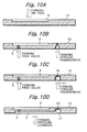
- FIGS. 10A-10D demonstrate a procedure for producing the ink jet head shown on FIG. 9.
- the ink pool 4 is formed in the glass sheet 10 by sand blasting in the same manner as in the previous embodiment (first step).
- FIG. 10B after a mask for masking the other major surface of the glass sheet 2 except for the portions expected to form the feed holes 5 and bores 17 has been positioned on the above surface, beams converging into the glass sheet 10 via the pattern of the bores 17 are emitted to the glass sheet 10 (second step), The beams are caused to focus on the positions of the glass sheet 10 expected to form the nozzles 15. If desired, the focuses of the beams on the glass sheet 10 may be adjusted independently of each other during radiation. Ultraviolet rays sequentially converging into the glass sheet via the through hole pattern expose a conical portion. The conical portion is etched in order to form a conical through bore including a nozzle.
- the third step of the previous embodiment is repeated to form the pressure chambers (fourth step). This is also followed by the fourth to sixth steps of the previous embodiment to complete an ink jet head.
- ultraviolet rays may be radiated after a mask for masking the surface of the glass sheet 10 opposite to the surface with the ink pool 4 except for the portions expected to form the feed holes 5 and nozzles 15 has been positioned an the above surface.
- ultraviolet rays converged via a lens will be radiated to the individual nozzle portion.
- the ultraviolet rays are focused at the positions for forming the nozzles 15.
- the second step may be modified as follows. First, a mask for masking the surface of the glass sheet 10 opposite to the surface with the ink pool 4 except for the portions expected to form the feed holes 5 and nozzles 15 is positioned on the above surface in order to form through holes identical in diameter with the nozzles 15. Subsequently, beams converging into the glass sheet 10 via the pattern of the bores 17 are emitted via a mask in order to form the conical portions. This easily provides the nozzles with the same diameter.
- both the nozzles 15 and bores 17 are formed in the head chip 14 and therefore accurately aligned with each other.
- such a configuration prevents adhesive from bulging out between the nozzles 15 and the pressure chambers 2 and enhances the accuracy of the ink jet head.
- Blocks of ink passageways each assigned to a particular color may be molded integrally with each other.
- a molding is more efficient and more accurate than color-by-color blocks adhered to each other.
- the feed holes, through passageways and bores may not extend perpendicularly to the general plane of the substrate.
- the piezoelectric device may be positioned perpendicularly to the direction in which the other members are stacked, in which case the transverse effect is available with the piezoelectric device.
Landscapes
- Engineering & Computer Science (AREA)
- Manufacturing & Machinery (AREA)
- Chemical & Material Sciences (AREA)
- Life Sciences & Earth Sciences (AREA)
- Chemical Kinetics & Catalysis (AREA)
- General Chemical & Material Sciences (AREA)
- Geochemistry & Mineralogy (AREA)
- Materials Engineering (AREA)
- Organic Chemistry (AREA)
- Particle Formation And Scattering Control In Inkjet Printers (AREA)
Applications Claiming Priority (2)
| Application Number | Priority Date | Filing Date | Title |
|---|---|---|---|
| JP10089970A JP3141840B2 (ja) | 1998-04-02 | 1998-04-02 | インクジェットプリントヘッドの製造方法 |
| JP8997098 | 1998-04-02 |
Publications (1)
| Publication Number | Publication Date |
|---|---|
| EP0949079A1 true EP0949079A1 (de) | 1999-10-13 |
Family
ID=13985550
Family Applications (1)
| Application Number | Title | Priority Date | Filing Date |
|---|---|---|---|
| EP99105199A Withdrawn EP0949079A1 (de) | 1998-04-02 | 1999-04-01 | Herstellungsverfahren für einen Tintenstrahldruckkopf |
Country Status (5)
| Country | Link |
|---|---|
| US (1) | US20020083588A1 (de) |
| EP (1) | EP0949079A1 (de) |
| JP (1) | JP3141840B2 (de) |
| AU (1) | AU740275B2 (de) |
| CA (1) | CA2268224A1 (de) |
Cited By (7)
| Publication number | Priority date | Publication date | Assignee | Title |
|---|---|---|---|---|
| EP1138492A1 (de) * | 2000-03-21 | 2001-10-04 | Nec Corporation | Tintenstrahlkopf und dazugehöriges Herstellungsverfahren |
| WO2004005030A3 (en) * | 2002-07-03 | 2004-05-06 | Spectra Inc | Printhead |
| EP1559556A3 (de) * | 2004-01-29 | 2006-10-04 | Hewlett-Packard Development Company, L.P. | Verfahren zur Herstellung eines Tintenstrahldruckkopfes |
| US7988247B2 (en) | 2007-01-11 | 2011-08-02 | Fujifilm Dimatix, Inc. | Ejection of drops having variable drop size from an ink jet printer |
| US8459768B2 (en) | 2004-03-15 | 2013-06-11 | Fujifilm Dimatix, Inc. | High frequency droplet ejection device and method |
| US8491076B2 (en) | 2004-03-15 | 2013-07-23 | Fujifilm Dimatix, Inc. | Fluid droplet ejection devices and methods |
| US8708441B2 (en) | 2004-12-30 | 2014-04-29 | Fujifilm Dimatix, Inc. | Ink jet printing |
Families Citing this family (2)
| Publication number | Priority date | Publication date | Assignee | Title |
|---|---|---|---|---|
| JP4635480B2 (ja) * | 2004-06-14 | 2011-02-23 | 富士ゼロックス株式会社 | インクジェット記録ヘッドおよびその製造方法 |
| JP5662664B2 (ja) * | 2008-12-19 | 2015-02-04 | 東京応化工業株式会社 | 加工基板及びその製造方法 |
Citations (7)
| Publication number | Priority date | Publication date | Assignee | Title |
|---|---|---|---|---|
| US2971853A (en) * | 1953-03-05 | 1961-02-14 | Corning Glass Works | Ceramic body and method of making it |
| DE3445761A1 (de) * | 1983-12-16 | 1985-06-27 | Pitney Bowes, Inc., Stamford, Conn. | Verfahren und herstellung einer wandleranordnung |
| JPS63128948A (ja) * | 1986-11-19 | 1988-06-01 | Sharp Corp | インクジエツトヘツド |
| EP0413340A1 (de) * | 1989-08-17 | 1991-02-20 | Seiko Epson Corporation | Tintenstrahlaufzeichnungskopf |
| US5028514A (en) * | 1988-04-30 | 1991-07-02 | Aeg Olympia Aktiengesellschaft | Method of producing an etched base plate for an ink print head |
| JPH04216939A (ja) * | 1990-12-18 | 1992-08-07 | Seiko Epson Corp | インクジェット記録ヘッド |
| EP0709200A1 (de) * | 1994-10-26 | 1996-05-01 | Mita Industrial Co. Ltd. | Druckkopf für Tintenstrahldrucker und sein Herstellungsverfahren |
-
1998
- 1998-04-02 JP JP10089970A patent/JP3141840B2/ja not_active Expired - Fee Related
-
1999
- 1999-04-01 EP EP99105199A patent/EP0949079A1/de not_active Withdrawn
- 1999-04-01 CA CA002268224A patent/CA2268224A1/en not_active Abandoned
- 1999-04-02 US US09/285,076 patent/US20020083588A1/en not_active Abandoned
- 1999-04-06 AU AU23607/99A patent/AU740275B2/en not_active Expired
Patent Citations (7)
| Publication number | Priority date | Publication date | Assignee | Title |
|---|---|---|---|---|
| US2971853A (en) * | 1953-03-05 | 1961-02-14 | Corning Glass Works | Ceramic body and method of making it |
| DE3445761A1 (de) * | 1983-12-16 | 1985-06-27 | Pitney Bowes, Inc., Stamford, Conn. | Verfahren und herstellung einer wandleranordnung |
| JPS63128948A (ja) * | 1986-11-19 | 1988-06-01 | Sharp Corp | インクジエツトヘツド |
| US5028514A (en) * | 1988-04-30 | 1991-07-02 | Aeg Olympia Aktiengesellschaft | Method of producing an etched base plate for an ink print head |
| EP0413340A1 (de) * | 1989-08-17 | 1991-02-20 | Seiko Epson Corporation | Tintenstrahlaufzeichnungskopf |
| JPH04216939A (ja) * | 1990-12-18 | 1992-08-07 | Seiko Epson Corp | インクジェット記録ヘッド |
| EP0709200A1 (de) * | 1994-10-26 | 1996-05-01 | Mita Industrial Co. Ltd. | Druckkopf für Tintenstrahldrucker und sein Herstellungsverfahren |
Non-Patent Citations (2)
| Title |
|---|
| PATENT ABSTRACTS OF JAPAN vol. 012, no. 376 (M - 750) 7 October 1988 (1988-10-07) * |
| PATENT ABSTRACTS OF JAPAN vol. 016, no. 563 (M - 1342) 4 December 1992 (1992-12-04) * |
Cited By (11)
| Publication number | Priority date | Publication date | Assignee | Title |
|---|---|---|---|---|
| EP1138492A1 (de) * | 2000-03-21 | 2001-10-04 | Nec Corporation | Tintenstrahlkopf und dazugehöriges Herstellungsverfahren |
| WO2004005030A3 (en) * | 2002-07-03 | 2004-05-06 | Spectra Inc | Printhead |
| US7052117B2 (en) | 2002-07-03 | 2006-05-30 | Dimatix, Inc. | Printhead having a thin pre-fired piezoelectric layer |
| US7303264B2 (en) | 2002-07-03 | 2007-12-04 | Fujifilm Dimatix, Inc. | Printhead having a thin pre-fired piezoelectric layer |
| US8162466B2 (en) | 2002-07-03 | 2012-04-24 | Fujifilm Dimatix, Inc. | Printhead having impedance features |
| EP1559556A3 (de) * | 2004-01-29 | 2006-10-04 | Hewlett-Packard Development Company, L.P. | Verfahren zur Herstellung eines Tintenstrahldruckkopfes |
| US8459768B2 (en) | 2004-03-15 | 2013-06-11 | Fujifilm Dimatix, Inc. | High frequency droplet ejection device and method |
| US8491076B2 (en) | 2004-03-15 | 2013-07-23 | Fujifilm Dimatix, Inc. | Fluid droplet ejection devices and methods |
| US8708441B2 (en) | 2004-12-30 | 2014-04-29 | Fujifilm Dimatix, Inc. | Ink jet printing |
| US9381740B2 (en) | 2004-12-30 | 2016-07-05 | Fujifilm Dimatix, Inc. | Ink jet printing |
| US7988247B2 (en) | 2007-01-11 | 2011-08-02 | Fujifilm Dimatix, Inc. | Ejection of drops having variable drop size from an ink jet printer |
Also Published As
| Publication number | Publication date |
|---|---|
| US20020083588A1 (en) | 2002-07-04 |
| CA2268224A1 (en) | 1999-10-02 |
| AU2360799A (en) | 1999-10-14 |
| JP3141840B2 (ja) | 2001-03-07 |
| AU740275B2 (en) | 2001-11-01 |
| JPH11286115A (ja) | 1999-10-19 |
Similar Documents
| Publication | Publication Date | Title |
|---|---|---|
| KR100232734B1 (ko) | 드롭 온 디맨드 인쇄장치 및 그 제조방법 | |
| US4829324A (en) | Large array thermal ink jet printhead | |
| EP0683048A2 (de) | Lithographisch definierte Strahleinheiten | |
| JP3199917B2 (ja) | インキジェット印字ヘッド | |
| US20060017778A1 (en) | Inkjet print head and manufacturing method thereof | |
| HK1000055B (en) | Drop-on-demand printing apparatus and method of manufacture thereof | |
| EP1911591B1 (de) | Herstellungsverfahren für einen Einspritzkopf und Einspritzkopf | |
| JPH02229050A (ja) | インクジェットプリントヘッドを製造する方法 | |
| EP0709200A1 (de) | Druckkopf für Tintenstrahldrucker und sein Herstellungsverfahren | |
| US6973703B2 (en) | Method for manufacturing an ink-jet head | |
| US20020083588A1 (en) | Method of producing an ink jet head | |
| EP0550030A2 (de) | Tintenstrahldruckkopf und sein Herstellungsverfahren | |
| US6286942B1 (en) | Ink jet recording head with mechanism for positioning head components | |
| EP1083048A1 (de) | Tintenstrahldruckkopf und verfahren zur dessen herstellung | |
| EP1075389B1 (de) | Verfahren zur herstellung eines tintenstrahldruckkopfes | |
| US5872580A (en) | Ink jet recording head with stacked individual head members and a manufacturing method thereof | |
| US6547375B2 (en) | Ink-jet head and manufacturing method thereof | |
| JP2003019805A (ja) | インクジェットヘッド及びその製造方法 | |
| US20010015740A1 (en) | Liquid jetting head | |
| US6174040B1 (en) | Inkjet printing head and inkjet printing head manufacturing method | |
| EP0813969B1 (de) | Verfahren zur Herstellung eines Aufzeichnungskopfes für eine elektrostatische Tintenstrahlaufzeichnungsvorrichtung | |
| US6315385B1 (en) | Self-locating orifice plate construction for thermal ink jet printheads | |
| JP3114766B2 (ja) | インクジェットヘッドおよびその製造方法 | |
| JP2008162110A (ja) | インクジェットヘッドおよびインクジェットヘッドの製造方法プ実装用配線基板 | |
| JPH1158747A (ja) | ノズル形成部材及びその製造方法並びにインクジェットヘッド |
Legal Events
| Date | Code | Title | Description |
|---|---|---|---|
| PUAI | Public reference made under article 153(3) epc to a published international application that has entered the european phase |
Free format text: ORIGINAL CODE: 0009012 |
|
| 17P | Request for examination filed |
Effective date: 19990806 |
|
| AK | Designated contracting states |
Kind code of ref document: A1 Designated state(s): DE GB IT |
|
| AX | Request for extension of the european patent |
Free format text: AL;LT;LV;MK;RO;SI |
|
| 17Q | First examination report despatched |
Effective date: 20000216 |
|
| AKX | Designation fees paid |
Free format text: DE GB IT |
|
| STAA | Information on the status of an ep patent application or granted ep patent |
Free format text: STATUS: THE APPLICATION IS DEEMED TO BE WITHDRAWN |
|
| 18D | Application deemed to be withdrawn |
Effective date: 20000627 |