EP0949077B1 - Procédé de projection d'un liquide électriquement conducteur et dispositif d'impression par jet d'encre continu utilisant ce procédé - Google Patents
Procédé de projection d'un liquide électriquement conducteur et dispositif d'impression par jet d'encre continu utilisant ce procédé Download PDFInfo
- Publication number
- EP0949077B1 EP0949077B1 EP99400831A EP99400831A EP0949077B1 EP 0949077 B1 EP0949077 B1 EP 0949077B1 EP 99400831 A EP99400831 A EP 99400831A EP 99400831 A EP99400831 A EP 99400831A EP 0949077 B1 EP0949077 B1 EP 0949077B1
- Authority
- EP
- European Patent Office
- Prior art keywords
- jet
- drops
- break
- points
- jets
- Prior art date
- Legal status (The legal status is an assumption and is not a legal conclusion. Google has not performed a legal analysis and makes no representation as to the accuracy of the status listed.)
- Expired - Lifetime
Links
- 238000000034 method Methods 0.000 title claims description 33
- 239000007788 liquid Substances 0.000 title claims description 15
- 238000007641 inkjet printing Methods 0.000 title claims description 6
- 230000000638 stimulation Effects 0.000 claims description 44
- 230000008569 process Effects 0.000 claims description 15
- 230000005684 electric field Effects 0.000 claims description 11
- 230000000737 periodic effect Effects 0.000 claims description 8
- 230000005284 excitation Effects 0.000 claims description 6
- 230000000295 complement effect Effects 0.000 claims description 3
- 238000004064 recycling Methods 0.000 claims description 3
- 238000007639 printing Methods 0.000 description 40
- 239000007921 spray Substances 0.000 description 6
- 241001379910 Ephemera danica Species 0.000 description 4
- 238000013461 design Methods 0.000 description 4
- 230000000694 effects Effects 0.000 description 4
- 238000005516 engineering process Methods 0.000 description 4
- 230000007704 transition Effects 0.000 description 4
- 241001080024 Telles Species 0.000 description 3
- 238000004519 manufacturing process Methods 0.000 description 3
- 230000001052 transient effect Effects 0.000 description 3
- 238000011144 upstream manufacturing Methods 0.000 description 3
- 230000001276 controlling effect Effects 0.000 description 2
- 238000005034 decoration Methods 0.000 description 2
- 238000006073 displacement reaction Methods 0.000 description 2
- 239000012535 impurity Substances 0.000 description 2
- 238000005507 spraying Methods 0.000 description 2
- 230000004936 stimulating effect Effects 0.000 description 2
- 238000012546 transfer Methods 0.000 description 2
- 241000135309 Processus Species 0.000 description 1
- 230000009471 action Effects 0.000 description 1
- 230000004075 alteration Effects 0.000 description 1
- 230000005540 biological transmission Effects 0.000 description 1
- 238000004140 cleaning Methods 0.000 description 1
- 239000004020 conductor Substances 0.000 description 1
- 239000013078 crystal Substances 0.000 description 1
- 239000006185 dispersion Substances 0.000 description 1
- 230000005520 electrodynamics Effects 0.000 description 1
- 239000012634 fragment Substances 0.000 description 1
- 238000013467 fragmentation Methods 0.000 description 1
- 238000006062 fragmentation reaction Methods 0.000 description 1
- 230000004048 modification Effects 0.000 description 1
- 238000012986 modification Methods 0.000 description 1
- 230000010363 phase shift Effects 0.000 description 1
- 238000012545 processing Methods 0.000 description 1
- 230000001105 regulatory effect Effects 0.000 description 1
- 238000012549 training Methods 0.000 description 1
Images


Classifications
-
- B—PERFORMING OPERATIONS; TRANSPORTING
- B41—PRINTING; LINING MACHINES; TYPEWRITERS; STAMPS
- B41J—TYPEWRITERS; SELECTIVE PRINTING MECHANISMS, i.e. MECHANISMS PRINTING OTHERWISE THAN FROM A FORME; CORRECTION OF TYPOGRAPHICAL ERRORS
- B41J2/00—Typewriters or selective printing mechanisms characterised by the printing or marking process for which they are designed
- B41J2/005—Typewriters or selective printing mechanisms characterised by the printing or marking process for which they are designed characterised by bringing liquid or particles selectively into contact with a printing material
- B41J2/01—Ink jet
- B41J2/07—Ink jet characterised by jet control
- B41J2/105—Ink jet characterised by jet control for binary-valued deflection
Definitions
- the invention relates to a projection method of an electrically conductive liquid in the form at least one continuous stimulated jet.
- the invention also relates to a device multi-nozzle printing using this process.
- a printing device can be used in all industrial fields related to marking, coding, addressing and industrial decoration.
- the continuous inkjet technique deflected, electrically conductive ink, maintained under pressure, escapes from a calibrated nozzle.
- the ink jet thus formed breaks at time intervals regular at a single point in space.
- This forced fragmentation of the inkjet is usually induced by periodic vibrations of a crystal piezoelectric placed upstream of the nozzle.
- the continuous jet turns into a train of identical and regular ink drops spaced.
- a first group of electrodes whose function is to transfer to each drop of the spray, selectively, a variable amount of electrical charge and predetermined. All the drops of the jet pass through then a second group of electrodes within which there is a constant electric field.
- Each drop undergoes then a deflection proportional to the electric charge previously assigned to it, and which points to a specific point on a print medium.
- the non-deflected drops are recovered by a gutter and recycled to an ink circuit.
- a specific device is usually provided to ensure a constant synchronization between the moments of jet break and the application of the charge signals of the drops.
- This technology is mainly characterized by the fact that a variable amount of electric charge is selectively transferred to each drop of jet, so that multiple levels of deflection are created.
- This feature allows a nozzle unique to print, by segments (lines of points of a given width), the entire pattern (character or graphic pattern). Moving from one segment to another is carried out by the continuous displacement, perpendicularly to the segments, of the printing medium opposite the printing device.
- multiple devices monobuses printing (generally two to four) can be grouped within the same box.
- Document EP-A-0 512 907 describes a multi-nozzle printing device (eight nozzles) using inkjet technology continuously deflected. By juxtaposing several devices multi-nozzle printing, more printing widths important can be obtained.
- Inkjet printing devices continuous stimulated using the continuous jet technique stand out from printing devices using the technique of continuous deflected jet mainly by the fact that only an amount of electric charge predetermined can be transferred on demand, with every drop of the spray. A single level of deflection of drops is then created.
- Printing characters or of patterns therefore requires the use of devices multi-nozzle printers, in which the distance between the nozzles generally coincide with the spacing between impacts on the print medium.
- the drops intended for printing (“drops to print "in the rest of the text) are the drops not deflected. This technique is particularly suitable for high speed printing applications such as addressing, printing proofs in high resolution color, etc.
- the cost problems originate from the multiplication of charge electrodes and multiplication high voltage electronic circuits connected to these electrodes, which induce a connection important and complex.
- this article proposes to use two groups of electrodes, each of which is formed by a flat electrode.
- each electrode is common to all jets and subject to constant electrical voltage.
- the selection of drops to print and drops to recycle is done then by the individual control of the stimulation of each of the ink jets from the print head. In this effect, an individual stimulation device each of the jets is planned.
- the associated connectors to stimulation devices is located upstream nozzles and therefore distant from the jets.
- she carries lower voltage levels than those are required to charge the drops. The effects of crosstalk are therefore reduced.
- the jet breaking point is located opposite the first electrode, or charging electrode, brought to a constant voltage V c .
- the drop which detaches at this instant then carries a charge Q1 and undergoes a deflection of angle ⁇ 1 in the field created by the second electrode, or deflection electrode, brought to a constant voltage V d .
- This drop is recovered by a gutter and recycled to the ink circuit of the printing device.
- the breaking distance When the breaking distance is shorter, due to the application of a high level stimulation signal on the jet, the latter breaks at a point situated slightly before the charging electrode.
- the charge Q2 carried by the drop is then lower than in the previous case.
- the deflection ⁇ 2 induced by the deflection plane is therefore also less.
- the drop then avoids the gutter and reaches the print medium.
- the difference between the two levels of stimulation of the jet is such that the distance d between the breaking points of the jet for each of these two levels is equal to the wavelength ⁇ of the stimulated jet, that is to say ie the train of drops.
- the first handicap stems from the fact that the distance d between the two break points of the jet is equal to the wavelength ⁇ of the drop train. This leads to a difficulty in operating the jet during the long break-short break transitions.
- the condition d ⁇ theoretically leads to the simultaneous detachment of the two drops.
- the kinetics of charge transfers is then different from that associated with a short-break-long break transition, which can induce different trajectories.
- any fluctuation of one or the other of the breaking distances inevitable in an actual implementation of the method, leads to a modification of the operating conditions of the jet.
- the start of such a device led printing, for ink jets escaping from the nozzles, during a transient phase during which aerodynamic braking predominates.
- a jet forms at the end of each jet ink volume larger than that drops formed during the steady state, and jet trajectory is temporarily altered.
- any fluctuation of the trajectory of the jets around their axis can also deflect slightly spray and lead to dirt on the electrode load placed in the immediate vicinity of jets, which usually causes short circuits between the jet and the electrode.
- document US-A-4 220 958 describes a method of stimulating an ink jet, in which jet disturbance is accomplished by excitation electro-hydrodynamics (EHD).
- the stimulation device EHD proposed in this document is composed of one or several electrodes placed near the jet, downstream of the nozzle, the length of each electrode being approximately equal to ⁇ / 2.
- the main object of the invention is a method electrically conductive liquid spray using the binary continuous jet technique described in the above-mentioned article by Donald J. DRAKE, without presenting the disadvantages of this technique.
- the invention relates to a method projection of liquid by continuous jet, in which the process of charging the drops from jets are controlled regardless of the sequence of drops emitted, and the trajectory of the printable drops is not a strictly monotonic function of the position of the breaking point within the device charge.
- said quantities are applied to the drops of different electrical charge by creating two contiguous areas located in the respective vicinity of the two breaking points and bringing these two areas to constant electrical potentials and this opposite signs.
- the jet can be passed successively between two pairs of oriented electrodes parallel to the jet and sized so that both break points are located between said electrodes, and applying on the two pairs of electrodes constant electrical voltages and signs opposed.
- each electrode in order to avoid the inconvenience related to the immediate proximity between the surface of the jet and the load plan, we advantageously place each electrode at least equal distance from the jet axis twice the diameter of it.
- the individual means of binary stimulation of each of the jets includes a piezoelectric element or thermo-resistive placed in the pressurized tank and individually controlled by an electronic circuit external.
- the individual means of binary stimulation of each of the jets includes two elements thermo-resistive placed in the pressurized tank, an external electrical circuit permanently delivering a periodic electrical signal for supplying a first of the thermo-resistive elements, corresponding to first breaking point and, on request, a signal complementary electric supply of the second thermo-resistive element, corresponding to the second breaking point.
- the individual means of stimulation binary of each of the jets includes a transducer individual placed in the pressurized tank and at minus a common electro-hydrodynamic excitation electrode placed near the jets, downstream of the nozzle, an external electrical circuit delivering permanently a periodic power signal electric excitation electrode electro-hydrodynamics, corresponding to the first point breakage and, on request, an electrical signal additional supply of the transducer individual, corresponding to the second breaking point.
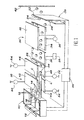
- Figure 1 shows schematically a continuous inkjet printing device implement the method of projecting a liquid electrically conductor according to the invention.
- the device comprises a pressurized tank 10, equipped with a plurality of calibrated nozzles 12 (three in the figure) from which escape, at a given speed V j , ink jets 14 parallel to each other and having between them a constant spacing.
- Each ink jet 14 is associated with an individual means 16 of binary stimulation, placed in the reservoir 10 and controlled individually by an external electronic circuit 18.
- Each individual means 16 of binary stimulation fixes, on demand, the place of breaking of each of the jets 14 at a short breaking point C , relatively close to the nozzle 12 or at a long breaking point L further from this nozzle.
- the drops formed at points C and L are designated by the references 22 and 24 respectively.
- the drops 22 and 24 are all emitted at the same given emission frequency F.
- a charging means 20 which will be described in more detail detail later, is placed in the vicinity of breaking points C and L. This charging means 20 is common to all ink jets 14. It applies different amounts of charge in drops 22 and 24, according to their breaking points.
- the device print Downstream of the charging means 20, the device print includes a sensor 26 designed to measure the speed of the ink jets 14. This sensor 26 is connected to an electronic circuit 28 which ensures the processing of data collected by the sensor. The circuit 28 is connected to a regulation loop (not shown) of the speed of the jets 14, according to an arrangement known to those skilled in the art. To simplify, the sensor 26 and its associated circuit have not been shown in Figures 2A to 4.
- the printing device Downstream of sensor 26, the printing device includes deflection means 30 which applies a same constant electric field on ink drops 22 and 24 previously electrically charged in the load means 20.
- This deflection means 30 comprises two planar electrodes 32 and 34, common to all ink jets 14. These electrodes 32 and 34 are arranged on both sides of the ink drop trains 22 and 24 and a constant voltage is applied between them by a supply circuit 36.
- the deflection means 30 directs the charged drops 24 to a gutter 38 which recycles them to a general ink circuit 40 of the device.
- the charging means 20 comprises two groups of planar electrodes, respectively 42, 44 and 46, 48, the electrodes of each group being placed on either side of the jets 14.
- the two groups of electrodes are separated one on the other by a distance D ( Figure 2A) parallel to the axes of the jets.
- D Figure 2A
- the total length of the two groups of electrodes, parallel to the axes of the jets, is called S.
- supply circuits 50 and 52 apply the same constant voltage V1 to the two electrodes 42 and 44 of the first group of electrodes and supply circuits 54 and 56 apply a same constant voltage V2 , of opposite sign to V1 , on the two electrodes 46 and 48 of the second group of electrodes.
- Two contiguous zones are thus created, in the vicinity of the breaking points C and L , respectively, brought to constant electrical potentials and of opposite signs.
- the electrodes 42 and 44 of the first group of electrodes are arranged symmetrically on either side of the jets 14 and each placed at a distance E from the axes of the jets.
- this distance E is greater than or equal to twice the diameter d j of the jets 14.
- the electrodes 46 and 48 of the second group of electrodes are also arranged symmetrically on either side of the jets 14 and at the same distance E from their axes.
- the selection of a drop 24 not intended for the printing of the support 42 takes place by controlling the individual means 16 of binary stimulation of the corresponding jet 14 by an electrical signal whose level V l is determined in order to induce the breaking of the jet at the predetermined long breaking point L, inside the charging means 20.
- the selection of a drop 22 intended for the printing of the support 42 is carried out by controlling the individual means 16 of binary stimulation of the corresponding jet by an electrical signal whose level V c will induce the breaking of the jet at the predetermined point of breaking short C also inside the charging means 20.
- the distance ⁇ D between the two breaking points C and L is strictly less than the wavelength ⁇ of the stimulated jets.
- Any sequence of drops 24 not intended for printing or of drops 22 intended for printing is created by generating, on the individual means 16 for stimulating each of the jets and at the frequency F of emission of the drops chosen, a signal gathering the corresponding sequence of level V c or V l .
- the trajectory of the drops to be printed 22 is therefore not a strictly monotonic function of the position of the breaking point within the charging device. On the contrary, the same point of impact is ensured on the printing medium, despite possible fluctuations in the short breaking point C. The print quality is thus ensured without any particular technical difficulty or increase in cost.
- the length S of the charging means 20 can be less than 2.5 mm, the voltage V1 applied to the electrodes 42 and 44 equal to 300 V, and the voltage V2 applied to the electrodes 46 and 48 equal to - 300 V.
- Each of the jets 14 has, for example, a diameter of 35 ⁇ m, a speed of 24 m / s and a stimulation frequency equal to 125 kHz.
- each of the individual stimulation means 16 binary consists of a piezoelectric element placed in the tank 10 and controlled individually by the external electronic circuit 18.
- the number of piezoelectric elements is equal to that nozzles 12 of the print head.
- each of the piezoelectric elements constituting the individual stimulation means 16 binary can be replaced by an element thermo-resistive generating disturbances of nature thermal.
- thermo-resistive their operation and manufacturing method, we will usefully refer to the document US-A-4,638,328.
- thermo-resistive element When each individual means 16 of binary stimulation consists of a single thermo-resistive element associated with each nozzle 12 of the print head, this element is supplied by an electrical signal composed of a sequence of voltages V c and V l , corresponding to the pattern to be printed.
- each of the individual means 16 of binary stimulation includes two heat-resistant elements 16a and 16b associated with each nozzle 12 of the print head.
- the first element 16a is supplied uninterruptedly by a periodic electrical signal of amplitude Vl . When it is the only one to be supplied, the jet is therefore broken at the point L furthest from the nozzle.
- the second element 16b located as appropriate upstream or downstream of the first, is only activated when a drop 22 is to be printed. It then receives an electrical signal, preferably a voltage pulse, the amplitude and phase shift of which relative to the periodic signal applied to the first element 16a lead to the displacement of the jet breaking point at the point C closest to the nozzle.
- an electrical signal preferably a voltage pulse
- a third embodiment of the means individual binary stimulation of each of the jets 14 is illustrated diagrammatically in FIG. 4.
- each individual means 16 of binary stimulation comprises an electrode 58, placed immediately downstream of the nozzles 12 and common to all of the jets.
- This electrode 58 constitutes a stimulation device by electrodynamic excitation (EHD).
- EHD electrodynamic excitation
- the electrode 58 the length of which is approximately equal to ⁇ / 2 , fixes the point of breakage of the jets at the point L furthest from the nozzles, when no other stimulation is applied to the jets.
- Each individual means 16 of binary stimulation further comprises an individual transducer 60, preferably of the thermoresistive type, associated with each of the jets inside the reservoir 10.
- the transducers 60 are only activated to move the breaking points to the point C closest to the nozzle, when a drop 22 is to be printed.
- the embodiment of FIG. 4 makes it possible to extend the life of the thermo-resistive transducers by reducing their stress.
- this process allows you to control the charging process droplets from the jets whatever the sequence of drops emitted.
- the electrodes of the charging device drops are not located at close proximity to jets.
- the trajectory drops to be printed is not a strictly function monotonic of the position of the breaking point at within the charging device.
- a jet printer multi-nozzle ink produced according to the invention can be used in all applications related to industrial marking and coding.
- the domain of addressing, which requires speed and width printing, also represents an area of application of the invention.
- the absence individual electrodes facing the jet increases the number of nozzles per unit length on the printing device tank. This allows application of the invention to industrial decoration which requires increased resolution, in addition high print speed.
Landscapes
- Particle Formation And Scattering Control In Inkjet Printers (AREA)
- Ink Jet (AREA)
Description
- on émet au moins un jet continu de liquide à une vitesse Vj donnée ;
- on stimule le jet de façon à le fragmenter, à la demande, en deux points de brisure prédéterminés distincts, pour former des gouttes de liquide à une fréquence d'émission F donnée ;
- on applique sur les gouttes des quantités de charge électrique différentes, selon leurs points de brisure ; puis
- on applique un même champ électrique sur les gouttes, de façon à ne dévier que les gouttes formées en un premier desdits points de brisure, relativement éloigné ;
- un réservoir pressurisé équipé de plusieurs buses aptes à émettre simultanément, à une vitesse Vj donnée, une pluralité de jets d'encre continus parallèles entre eux ;
- un moyen individuel de stimulation binaire de chacun des jets, apte à fragmenter ceux-ci, à la demande, en deux points de brisure prédéterminés distincts, pour former des gouttes d'encre à une fréquence d'émission F donnée ;
- un moyen de charge, commun à la pluralité de jets d'encre, pour appliquer sur les gouttes d'encre des quantités de charge électrique différentes, selon leurs points de brisure ;
- un moyen de déflexion, commun à la pluralité de jets d'encre, pour appliquer un même champ électrique sur les gouttes, de façon à ne dévier que les gouttes formées en un premier des points de brisure, relativement éloigné des buses ; et
- une gouttière de recyclage des gouttes déviées vers le réservoir pressurisé ;
- la figure 1 est une vue en perspective qui représente schématiquement un dispositif d'impression par jet d'encre continu conforme à l'invention ;
- les figures 2A et 2B sont des vues de côté qui illustrent très schématiquement les processus de charge et de déflexion dans le dispositif de la figure 1, respectivement pour les gouttes destinées au recyclage et pour les gouttes servant à l'impression ;
- la figure 3 est une vue en coupe comparable aux figures 2A et 2B illustrant une deuxième forme de réalisation de l'invention, dans laquelle chaque moyen individuel de stimulation binaire comprend deux éléments thermo-résistifs ; et
- la figure 4 est une vue en coupe schématique comparable aux figures 2A, 2B et 3, illustrant une troisième forme de réalisation de l'invention, dans laquelle chaque moyen individuel de stimulation binaire comprend un. élément thermo-résistif et un dispositif commun de stimulation EHD.
- la charge induite sur les gouttes à recycler 24, détachées du jet au point de brisure longue L, soit telle que le champ électrique constant engendré par le moyen de déflexion 30 incurve la trajectoire de ces gouttes vers la gouttière 38 (figure 2A)
- la charge induite sur les gouttes à imprimer 22, détachées du jet au point de brisure courte C, ainsi que dans une zone centrée autour de ce point et de longueur approximativement égale à λ/4, soit telle que le champ électrique constant produit par le moyen de déflexion 30 ne modifie pas la trajectoire de ces gouttes, qui peuvent ensuite atteindre le support d'impression 42 (figure 2B).
Claims (11)
- Procédé de projection de liquide électriquement conducteur, dans lequel :caractérisé par le fait qu'on stimule le jet (14) de façon telle que les deux points de brisure (C, L) soient séparés par une distance ΔD strictement inférieure à la longueur d'onde λ du jet, définie par la relation λ = Vj /F, et on applique approximativement une même quantité de charge sur toutes les gouttes (22) formées dans une zone centrée sur le deuxième point de brisure (C) et de longueur sensiblement égale à λ/4.on émet au moins un jet continu de liquide (14) à une vitesse Vj donnée ;on stimule le jet de façon à le fragmenter, à la demande, en deux points de brisure prédéterminés distincts (C, L), pour former des gouttes (22,24) de liquide à une fréquence d'émission F donnée ;on applique sur les gouttes (22,24) des quantités de charge électrique différentes, selon leurs points de brisure (C, L) ; puison applique un même champ électrique sur les gouttes, de façon à ne dévier que les gouttes (24) formées en un premier (L) desdits points de brisure, relativement éloigné ;
- Procédé selon la revendication 1, dans lequel on applique sur les gouttes (22,24) lesdites quantités de charge électrique différentes en créant deux zones contiguës situées au voisinage respectif des deux points de brisure (C, L) et en portant ces deux zones à des potentiels électriques constants et de signes opposés.
- Procédé selon la revendication 2, dans lequel on fait passer le jet successivement entre deux paires d'électrodes (42,44 ; 46,48) orientées parallèlement au jet (14) et dimensionnées afin que les deux points de brisure (C,L) soient localisés entre lesdites électrodes, et en appliquant sur les deux paires d'électrodes des tensions électriques (V1,V2) constantes et de signes opposés.
- Procédé selon la revendication 3, dans lequel on place chaque électrode (42,44 ; 46,48) à une distance (E) de l'axe du jet (14) au moins égale à deux fois le diamètre de celui-ci.
- Procédé selon l'une quelconque des revendications précédentes, dans lequel on émet simultanément plusieurs jets continus de liquide (14), parallèles entre eux, on stimule séparément chaque jet, on applique simultanément sur les gouttes (22,24) de tous les jets lesdites quantités de charge électrique différentes, puis on applique simultanément un même champ électrique sur les gouttes.
- Dispositif d'impression par jets d'encre continus, comprenant :caractérisé par le fait que le moyen individuel (16) de stimulation binaire de chacun des jets (14) est piloté par des niveaux de tension prédéfinis (Vc , Vl ) tels que les deux points de brisure (C,L) soient séparés par une distance (ΔD) strictement inférieure à la longueur d'onde λ du jet définie par la relation λ = V j /F, lé moyen de charge (20) étant apte à appliquer approximativement une même quantité de charge sur toutes les gouttes (22) formées dans une zone centrée sur le deuxième point de brisure (C) et de longueur sensiblement égale à λ/4.un réservoir pressurisé (10) équipé de plusieurs buses (12) aptes à émettre simultanément, à une vitesse Vj donnée, une pluralité de jets d'encre continus (14) parallèles entre eux ;un moyen individuel (16) de stimulation binaire de chacun des jets, apte à fragmenter ceux-ci, à la demande, en deux points de brisure prédéterminés distincts (C, L), pour former des gouttes d'encre (22,24) à une fréquence d'émission F donnée ;un moyen de charge (20), commun à la pluralité de jets d'encre (14), pour appliquer sur les gouttes d'encre (22,24) des quantités de charge électrique différentes, selon leurs points de brisure ;un moyen de déflexion (30), commun à la pluralité de jets d'encre (14), pour appliquer un même champ électrique sur les gouttes, de façon à ne dévier que les gouttes (24) formées en un premier (L) des points de brisure, relativement éloigné des buses ; etune gouttière (38) de recyclage des gouttes déviées (24) vers le réservoir pressurisé (10)
- Dispositif selon la revendication 6, dans lequel le moyen de charge (20) comprend deux paires d'électrodes (42,44 ; 46,48) orientées parallèlement aux jets et dimensionnées afin que les points de brisure (C,L) soient localisés entre lesdites électrodes, et des moyens (50,52 ; 54,56) pour appliquer des tensions électriques constantes et de signes opposés sur les deux paires d'électrodes.
- Dispositif selon la revendication 7, dans lequel les électrodes (42,44 ; 46,48) sont planes et placées à une distance (E) de l'axe de chacun des jets (14), au moins égale à deux fois le diamètre des jets.
- Dispositif selon l'une quelconque des revendications 6 à 8, dans lequel le moyen individuel de stimulation binaire de chacun des jets (14) comprend un élément (16) piézoélectrique ou thermo-résistif placé dans le réservoir pressurisé (10) et piloté individuellement par un circuit électronique externe (18).
- Dispositif selon l'une quelconque des revendications 6 à 8, dans lequel le moyen individuel (16) de stimulation binaire de chacun des jets (14) comprend deux éléments thermo-résistifs (16a,16b) placés dans le réservoir pressurisé (10), un circuit électrique externe (18) délivrant en permanence un signal électrique périodique d'alimentation d'un premier des éléments thermo-résistifs, correspondant au premier point de brisure (L) et, à la demande, un signal électrique complémentaire d'alimentation du deuxième élément thermo-résistif (16b), correspondant au deuxième point de brisure (C).
- Dispositif selon l'une quelconque des revendications 6 à 8, dans lequel le moyen individuel (16) de stimulation binaire de chacun des jets (14) comprend un transducteur individuel (60) placé dans le réservoir pressurisé (10) et au moins une électrode (58) commune d'excitation électro-hydrodynamique placée à proximité des jets, en aval de la buse (12), un circuit électrique externe (18) délivrant en permanence un signal périodique d'alimentation électrique de l'électrode (58) d'excitation électro-hydrodynamique, correspondant au premier point de brisure (L) et, à la demande, un signal électrique complémentaire d'alimentation du transducteur individuel (60), correspondant au deuxième point de brisure (C).
Applications Claiming Priority (2)
| Application Number | Priority Date | Filing Date | Title |
|---|---|---|---|
| FR9804561A FR2777211B1 (fr) | 1998-04-10 | 1998-04-10 | Procede de projection d'un liquide electriquement conducteur et dispositif d'impression par jet d'encre continu utilisant ce procede |
| FR9804561 | 1998-04-10 |
Publications (2)
| Publication Number | Publication Date |
|---|---|
| EP0949077A1 EP0949077A1 (fr) | 1999-10-13 |
| EP0949077B1 true EP0949077B1 (fr) | 2003-09-17 |
Family
ID=9525153
Family Applications (1)
| Application Number | Title | Priority Date | Filing Date |
|---|---|---|---|
| EP99400831A Expired - Lifetime EP0949077B1 (fr) | 1998-04-10 | 1999-04-06 | Procédé de projection d'un liquide électriquement conducteur et dispositif d'impression par jet d'encre continu utilisant ce procédé |
Country Status (5)
| Country | Link |
|---|---|
| US (1) | US6273559B1 (fr) |
| EP (1) | EP0949077B1 (fr) |
| DE (1) | DE69911289T2 (fr) |
| ES (1) | ES2207918T3 (fr) |
| FR (1) | FR2777211B1 (fr) |
Families Citing this family (36)
| Publication number | Priority date | Publication date | Assignee | Title |
|---|---|---|---|---|
| FR2799688B1 (fr) * | 1999-10-15 | 2001-11-30 | Imaje Sa | Imprimante et procede d'impression par jets d'encre |
| US6457807B1 (en) * | 2001-02-16 | 2002-10-01 | Eastman Kodak Company | Continuous ink jet printhead having two-dimensional nozzle array and method of redundant printing |
| FR2851495B1 (fr) * | 2003-02-25 | 2006-06-30 | Imaje Sa | Imprimante a jet d'encre |
| FR2890596B1 (fr) * | 2005-09-13 | 2007-10-26 | Imaje Sa Sa | Dispositif de charge et deflexion de gouttes pour impression a jet d'encre |
| US7673976B2 (en) * | 2005-09-16 | 2010-03-09 | Eastman Kodak Company | Continuous ink jet apparatus and method using a plurality of break-off times |
| US7273270B2 (en) * | 2005-09-16 | 2007-09-25 | Eastman Kodak Company | Ink jet printing device with improved drop selection control |
| FR2892052B1 (fr) * | 2005-10-13 | 2011-08-19 | Imaje Sa | Impression par deflexion differentielle de jet d'encre |
| US7892461B2 (en) * | 2005-11-04 | 2011-02-22 | Heubach Gmbh | Method for the production and use of pigmented thermoplastic material comprising a flow enhancer in the form of a dissolved salt |
| FR2906755B1 (fr) * | 2006-10-05 | 2009-01-02 | Imaje Sa Sa | Impression par deflexion d'un jet d'encre par un champ variable. |
| US8740359B2 (en) * | 2008-08-07 | 2014-06-03 | Eastman Kodak Company | Continuous inkjet printing system and method for producing selective deflection of droplets formed from two different break off lengths |
| US7938516B2 (en) * | 2008-08-07 | 2011-05-10 | Eastman Kodak Company | Continuous inkjet printing system and method for producing selective deflection of droplets formed during different phases of a common charge electrode |
| FR2938207B1 (fr) * | 2008-11-12 | 2010-12-24 | Imaje Sa | Imprimante munie d'un generateur de gouttes a jet continu binaire a deflexion et vitesse d'impression optimales |
| US8573757B2 (en) * | 2009-03-26 | 2013-11-05 | North Carolina Agricultural And Technical State University | Methods and apparatus of manufacturing micro and nano-scale features |
| FR2955801B1 (fr) | 2010-02-01 | 2012-04-13 | Markem Imaje | Dispositif formant pupitre d'imprimante a jet d'encre continu, a concentrations de vapeur de solvant a l'interieur et autour du pupitre diminuees |
| US8529021B2 (en) | 2011-04-19 | 2013-09-10 | Eastman Kodak Company | Continuous liquid ejection using compliant membrane transducer |
| US8398210B2 (en) | 2011-04-19 | 2013-03-19 | Eastman Kodak Company | Continuous ejection system including compliant membrane transducer |
| WO2012145260A1 (fr) | 2011-04-19 | 2012-10-26 | Eastman Kodak Company | Système d'éjection continue comprenant un transducteur à membrane déformable |
| US8469496B2 (en) | 2011-05-25 | 2013-06-25 | Eastman Kodak Company | Liquid ejection method using drop velocity modulation |
| US8465129B2 (en) | 2011-05-25 | 2013-06-18 | Eastman Kodak Company | Liquid ejection using drop charge and mass |
| CN103547455B (zh) | 2011-05-25 | 2015-08-26 | 伊斯曼柯达公司 | 利用液滴电荷和质量的液体喷射 |
| US8382259B2 (en) | 2011-05-25 | 2013-02-26 | Eastman Kodak Company | Ejecting liquid using drop charge and mass |
| US8657419B2 (en) | 2011-05-25 | 2014-02-25 | Eastman Kodak Company | Liquid ejection system including drop velocity modulation |
| EP2714406B1 (fr) | 2011-05-25 | 2016-12-14 | Eastman Kodak Company | Système d'éjection de liquide avec modulation de vitesse des gouttes |
| FR2975632A1 (fr) * | 2011-05-27 | 2012-11-30 | Markem Imaje | Imprimante a jet d'encre continu binaire |
| US8651632B2 (en) | 2012-03-20 | 2014-02-18 | Eastman Kodak Company | Drop placement error reduction in electrostatic printer |
| US8646883B2 (en) | 2012-03-20 | 2014-02-11 | Eastman Kodak Company | Drop placement error reduction in electrostatic printer |
| US8651633B2 (en) | 2012-03-20 | 2014-02-18 | Eastman Kodak Company | Drop placement error reduction in electrostatic printer |
| US8646882B2 (en) | 2012-03-20 | 2014-02-11 | Eastman Kodak Company | Drop placement error reduction in electrostatic printer |
| US8585189B1 (en) | 2012-06-22 | 2013-11-19 | Eastman Kodak Company | Controlling drop charge using drop merging during printing |
| US8641175B2 (en) | 2012-06-22 | 2014-02-04 | Eastman Kodak Company | Variable drop volume continuous liquid jet printing |
| US8696094B2 (en) | 2012-07-09 | 2014-04-15 | Eastman Kodak Company | Printing with merged drops using electrostatic deflection |
| US8888256B2 (en) | 2012-07-09 | 2014-11-18 | Eastman Kodak Company | Electrode print speed synchronization in electrostatic printer |
| CN105015166A (zh) * | 2015-07-20 | 2015-11-04 | 厦门英杰华机电科技有限公司 | Cij喷码机分段式高压偏转系统 |
| FR3045459B1 (fr) | 2015-12-22 | 2020-06-12 | Dover Europe Sarl | Tete d'impression ou imprimante a jet d'encre a consommation de solvant reduite |
| CN109808310B (zh) * | 2019-03-07 | 2020-11-06 | 浙江鸣春纺织股份有限公司 | 一种喷码机连续喷墨打印装置 |
| CN110816063B (zh) * | 2019-12-17 | 2025-01-14 | 清远卓立标识科技有限公司 | 一种喷码装置偏转电极及喷码装置 |
Family Cites Families (10)
| Publication number | Priority date | Publication date | Assignee | Title |
|---|---|---|---|---|
| US4220958A (en) | 1978-12-21 | 1980-09-02 | Xerox Corporation | Ink jet electrohydrodynamic exciter |
| CA1158706A (fr) * | 1979-12-07 | 1983-12-13 | Carl H. Hertz | Methode et dispositif de controle de la charge electrique de goutelettes, et imprimante au jet d'encre garnie du dispositif |
| US4417256A (en) * | 1980-05-09 | 1983-11-22 | International Business Machines Corporation | Break-off uniformity maintenance |
| JPS5831765A (ja) * | 1981-08-20 | 1983-02-24 | Ricoh Co Ltd | インクジエツト記録装置 |
| EP0149739B1 (fr) * | 1984-01-20 | 1988-08-03 | Codi-Jet Markierungs Systeme GmbH | Méthode et appareil pour l'alimentation en encre d'une imprimante à projection d'encre |
| US4638328A (en) | 1986-05-01 | 1987-01-20 | Xerox Corporation | Printhead for an ink jet printer |
| US4734705A (en) * | 1986-08-11 | 1988-03-29 | Xerox Corporation | Ink jet printer with satellite droplet control |
| FR2676023B1 (fr) | 1991-05-03 | 1993-07-23 | Imaje | Tete de deflexion multijet modulaire et procede de fabrication. |
| JPH06183003A (ja) * | 1992-08-03 | 1994-07-05 | Nec Eng Ltd | インクジェットプリンタ |
| US5523778A (en) * | 1993-12-07 | 1996-06-04 | Videojet Systems International, Inc. | Segmented charge tunnel for drop charging in a printhead |
-
1998
- 1998-04-10 FR FR9804561A patent/FR2777211B1/fr not_active Expired - Fee Related
-
1999
- 1999-04-01 US US09/283,153 patent/US6273559B1/en not_active Expired - Fee Related
- 1999-04-06 DE DE69911289T patent/DE69911289T2/de not_active Expired - Fee Related
- 1999-04-06 ES ES99400831T patent/ES2207918T3/es not_active Expired - Lifetime
- 1999-04-06 EP EP99400831A patent/EP0949077B1/fr not_active Expired - Lifetime
Also Published As
| Publication number | Publication date |
|---|---|
| ES2207918T3 (es) | 2004-06-01 |
| DE69911289D1 (de) | 2003-10-23 |
| EP0949077A1 (fr) | 1999-10-13 |
| US6273559B1 (en) | 2001-08-14 |
| FR2777211B1 (fr) | 2000-06-16 |
| DE69911289T2 (de) | 2004-06-17 |
| FR2777211A1 (fr) | 1999-10-15 |
Similar Documents
| Publication | Publication Date | Title |
|---|---|---|
| EP0949077A1 (fr) | Procédé de projection d'un liquide électriquement conducteur et dispositif d'impression par jet d'encre continu utilisant ce procédé | |
| EP1628832B1 (fr) | Imprimante a jet d'encre. | |
| EP0521764A1 (fr) | Procédé de projection de liquide et dispositif d'impression haute-résolution dans une imprimante à jet d'encre continu mettant en oeuvre ce procédé | |
| EP0856403B1 (fr) | Tête d'imprimante à éjection d'encre et procédé | |
| EP1469997B1 (fr) | Tete d'impression a double buse d'axes convergents et imprimante equipee | |
| EP1106371B1 (fr) | Imprimante à fabrication simplifiée et procédé de réalisation | |
| US5036337A (en) | Thermal ink jet printhead with droplet volume control | |
| EP1234670B1 (fr) | Tête d'impression et imprimante à électrodes de déflexion améliorées | |
| JPH11216867A (ja) | 2進静電偏向による連続式インクジェットプリンタ | |
| US20100182366A1 (en) | Formation of image by image forming apparatus with overlapping area | |
| FR2906755A1 (fr) | Impression par deflexion d'un jet d'encre par un champ variable. | |
| US8100510B2 (en) | Inkjet printhead system and method using laser-based heating | |
| FR2890596A1 (fr) | Dispositif de charge et deflexion de gouttes pour impression a jet d'encre | |
| JP2010264761A (ja) | インクジェットによるプリント方法 | |
| FR2952851A1 (fr) | Imprimante a jet d'encre continu a qualite et autonomie d'impression ameliorees | |
| EP0911165B1 (fr) | Imprimante à jet d'encre continu avec deviation variable des goutelettes par contact | |
| GB9802871D0 (en) | Operation of droplet deposition apparatus | |
| EP0365454B1 (fr) | Procédé d'impression haute résolution au moyen de gouttes d'encre satellites, mis en oeuvre dans une imprimante à jet d'encre continu | |
| EP1092542B1 (fr) | Imprimante et procédé d'impression par jets d'encre | |
| FR2892052A1 (fr) | Impression par deflexion differentielle de jet d'encre | |
| FR2975632A1 (fr) | Imprimante a jet d'encre continu binaire | |
| US6498615B1 (en) | Ink printing with variable drop volume separation | |
| FR2676022A1 (fr) | Tete d'enregistrement a jet d'encre. | |
| JPH08252918A (ja) | インクジェット記録装置 | |
| EP1060889B1 (fr) | Tête d'impression à jet d'encre continu ayant un élément chauffant avec une configuration symétrique |
Legal Events
| Date | Code | Title | Description |
|---|---|---|---|
| PUAI | Public reference made under article 153(3) epc to a published international application that has entered the european phase |
Free format text: ORIGINAL CODE: 0009012 |
|
| AK | Designated contracting states |
Kind code of ref document: A1 Designated state(s): DE ES GB IT |
|
| AX | Request for extension of the european patent |
Free format text: AL;LT;LV;MK;RO;SI |
|
| 17P | Request for examination filed |
Effective date: 19991217 |
|
| RAP1 | Party data changed (applicant data changed or rights of an application transferred) |
Owner name: IMAJE S.A. |
|
| AKX | Designation fees paid |
Free format text: DE ES GB IT |
|
| GRAH | Despatch of communication of intention to grant a patent |
Free format text: ORIGINAL CODE: EPIDOS IGRA |
|
| RIN1 | Information on inventor provided before grant (corrected) |
Inventor name: PERRIN, MAX Inventor name: VAGO, STEPHANE |
|
| GRAS | Grant fee paid |
Free format text: ORIGINAL CODE: EPIDOSNIGR3 |
|
| GRAA | (expected) grant |
Free format text: ORIGINAL CODE: 0009210 |
|
| AK | Designated contracting states |
Kind code of ref document: B1 Designated state(s): DE ES GB IT |
|
| REG | Reference to a national code |
Ref country code: GB Ref legal event code: FG4D Free format text: NOT ENGLISH |
|
| REF | Corresponds to: |
Ref document number: 69911289 Country of ref document: DE Date of ref document: 20031023 Kind code of ref document: P |
|
| GBT | Gb: translation of ep patent filed (gb section 77(6)(a)/1977) |
Effective date: 20040107 |
|
| PGFP | Annual fee paid to national office [announced via postgrant information from national office to epo] |
Ref country code: ES Payment date: 20040322 Year of fee payment: 6 |
|
| PGFP | Annual fee paid to national office [announced via postgrant information from national office to epo] |
Ref country code: GB Payment date: 20040331 Year of fee payment: 6 |
|
| PGFP | Annual fee paid to national office [announced via postgrant information from national office to epo] |
Ref country code: DE Payment date: 20040503 Year of fee payment: 6 |
|
| REG | Reference to a national code |
Ref country code: ES Ref legal event code: FG2A Ref document number: 2207918 Country of ref document: ES Kind code of ref document: T3 |
|
| PLBE | No opposition filed within time limit |
Free format text: ORIGINAL CODE: 0009261 |
|
| STAA | Information on the status of an ep patent application or granted ep patent |
Free format text: STATUS: NO OPPOSITION FILED WITHIN TIME LIMIT |
|
| 26N | No opposition filed |
Effective date: 20040618 |
|
| PG25 | Lapsed in a contracting state [announced via postgrant information from national office to epo] |
Ref country code: IT Free format text: LAPSE BECAUSE OF NON-PAYMENT OF DUE FEES Effective date: 20050406 Ref country code: GB Free format text: LAPSE BECAUSE OF NON-PAYMENT OF DUE FEES Effective date: 20050406 |
|
| PG25 | Lapsed in a contracting state [announced via postgrant information from national office to epo] |
Ref country code: ES Free format text: LAPSE BECAUSE OF NON-PAYMENT OF DUE FEES Effective date: 20050407 |
|
| PG25 | Lapsed in a contracting state [announced via postgrant information from national office to epo] |
Ref country code: DE Free format text: LAPSE BECAUSE OF NON-PAYMENT OF DUE FEES Effective date: 20051101 |
|
| GBPC | Gb: european patent ceased through non-payment of renewal fee |
Effective date: 20050406 |
|
| REG | Reference to a national code |
Ref country code: ES Ref legal event code: FD2A Effective date: 20050407 |