EP0948982B1 - Flüssigkeitsverteiler für Trennkolonnen - Google Patents
Flüssigkeitsverteiler für Trennkolonnen Download PDFInfo
- Publication number
- EP0948982B1 EP0948982B1 EP98810307A EP98810307A EP0948982B1 EP 0948982 B1 EP0948982 B1 EP 0948982B1 EP 98810307 A EP98810307 A EP 98810307A EP 98810307 A EP98810307 A EP 98810307A EP 0948982 B1 EP0948982 B1 EP 0948982B1
- Authority
- EP
- European Patent Office
- Prior art keywords
- outflow
- accordance
- liquid distributor
- liquid
- elements
- Prior art date
- Legal status (The legal status is an assumption and is not a legal conclusion. Google has not performed a legal analysis and makes no representation as to the accuracy of the status listed.)
- Expired - Lifetime
Links
Images


Classifications
-
- B—PERFORMING OPERATIONS; TRANSPORTING
- B01—PHYSICAL OR CHEMICAL PROCESSES OR APPARATUS IN GENERAL
- B01D—SEPARATION
- B01D3/00—Distillation or related exchange processes in which liquids are contacted with gaseous media, e.g. stripping
- B01D3/008—Liquid distribution
Definitions
- the invention relates to a liquid distributor for separation columns according to Preamble of claim 1 and a column with the distributor.
- the liquid distributor for columns comprises at least one tub or tubular part made of a rigid material.
- Outflow elements compliant, especially elastomeric material are in breakthroughs of tub or tubular part inserted tightly.
- One to be distributed Liquid can pass through at least one opening in each Drain outflow element.
- This opening has a precisely definable Geometry on. Thanks to their flexibility, the outflow elements can be the breakthroughs tight despite their geometric irregularities deploy. The geometry of the outlet openings remains largely unimpaired.
- claims 2 to 8 relate to advantageous embodiments of the distributor according to the invention.
- the subject of claim 9 is a Outflow element
- claims 10 and 11 relate to a column with distributors according to the invention.
- the solution according to the invention can also be used advantageously in columns are used, in which usually metallic liquid distributors are used.
- the Discharge elements by means of plug connections in openings in tubs or tubular parts can be installed.
- the plug connection allows one quick exchange, so that instead of the entire distributor only the Outflow elements must be replaced.
- FIG. 1 shown in detail in FIG. 1 comprises within one Column wall 10 a distributor 2 with a trough-shaped part 3 and Outflow elements 4, which are arranged above a packing section 5 is.
- a mass and heat exchange between a liquid 6 to be distributed (outflow direction 6 ') and a second one fluid medium, especially a gas, perform. They are the ones Outlet elements 4 in a regular, on the structure of the pack 5 coordinated pattern arranged.
- the outflow elements 4 form in FIG. 1 Blind holes; but they can also be arranged laterally in the distributor 2 Exit holes may be provided.
- the outflow elements 4 of the distributor 2 according to the invention are suitable for thick-walled ceramic tubs 3 particularly good. They are - see Fig. 2 - in Openings 30 are used, the cross sections of which extend in the outflow direction 6 ' rejuvenate or remain constant. In the case of rejuvenation results there is simply a seal on the interface between the breakthrough and outflow element 4. However, sealing rings can also be used as additional Components of the outflow elements 4 may be provided.
- the material of the Outflow elements 4 very flexible.
- the rigid material of the trough-shaped part 3 then gives good support, thanks to which geometric properties and the positioning of the outflow elements 4 largely preserved.
- the outflow element 4 of FIG. 2 is composed of a part 4a on the inlet side and an outlet-side part 4b designed as a fixing part, together. From the upper side 31 of the tub 3, the side of the Liquid entry, part 4a is inserted into the opening 30. The part 4a is formed on the inlet side with a pot-shaped recess 41, in the Bottom 42 an outlet opening 40 is arranged.
- This part 4a is with Advantage from an elastomeric plastic - for example PFA (Perfluoroalkyl vinyl ether copolymer) for operating temperatures up to around 250 ° C or another fluoropolymer - and by means of a Injection molding process made.
- the outflow opening 40 thus has a precise predeterminable geometry. If you choose for the diameter of the Outflow opening 40 a value which is greater than the thickness of the bottom 42, the outflow conditions are thus reproducible; furthermore is the The amount of liquid flowing through can be calculated precisely.
- the upper region 41 of the inlet-side part 4a which extends up to one extends lower edge 43 has a corresponding to the opening 30 Shape such that along a contact surface between the area 41 and practically no liquid flow off the surface of the opening 30 can.
- the lower area 44 of the inlet-side part 4a is cylindrical Tube formed, which is not in contact with the surface of the breakthrough 30th Has.
- the fixing part 4b which is also advantageously made of an elastomer is produced, can be via the tube 44 of the inlet-side part 4a push (arrows 46 '), with an elastically stretchable snap ring 45 the tube 44 spanned. Fine ribs 44a on the tube 44 result in cooperation with a lower edge 45a of the snap ring 45 a fixation.
- the Fixing part 4b which has a cup-shaped shell 46, is so far over the tube 44 pushed that the shell 46 under a compressive stress with its upper edge 46a rests on the outside 32 of the tub 3.
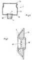
- FIG. 3 shows another baffle plate 7 with an outflow element 4b outlet-side tube 44.
- the Baffle plate 7 the same as the fixing part 4b in FIG. 2 with a snap ring 47 attached.
- This snap ring 47 can be part of a fixation of the Be outflow element, or it can also be an additional part next to one Fixing part 4b may be provided.
- the baffle plate 7 can also be reversed Be inclined towards the vertical so that an upward flowing gas is less hindered.
- outflow element 4 shows a one-piece outflow element 4 made of an elastic material shown, which comprises fixing parts 44 'with which the outflow element 4 is held non-slip in the opening 30.
- Such an outflow element 4 can only be used if the geometry of the opening with a inexpensive method can be precisely specified.
- FIG. 5 shows a variant in which the fixing parts 440 are more elastic "Barbs" are formed.
- the barb shown includes one Flank 441 with a flexible piece 442, which when inserted on the Surface of the opening 30 slides along and then unfolds.
- the upper edge 442a hooks on the outer surface 32 of the tub 3 a.
- the liquid distributor 1 according to the invention - see FIG. 6 - can also be used in metallic distribution channels 3 'are installed, for example tubular are formed and a trough-shaped lower part 33 and a include removable cover 34.
- a discharge element 4, for example one according to FIG. 4, is in a cylindrical tube piece 30 'of the lower part 33 used.
- FIG. 7 shows a further exemplary embodiment for an outflow element 4, which in a circular opening in a metallic distributor wall 33 can be used is.
- an outflow element 4 is very simple and quick to replace. As already mentioned above, this is when the column changes load from Advantage, since it is no longer necessary to change the entire distributor.
Description
- Fig. 1
- in schematischer Darstellung einen Ausschnitt aus einer Kolonne mit erfindungsgemässem Flüssigkeitsverteiler,
- Fig. 2
- ein zweiteiliges Ausflusselement,
- Fig. 3
- eine Prallplatte zu einem erfindungsgemässen Verteiler,
- Fig. 4
- ein einteiliges Ausflusselement,
- Fig. 5
- ein weiteres einteiliges Ausflusselement,
- Fig. 6
- einen Querschnitt durch ein Verteilerrohr aus Metall und
- Fig. 7
- einen Querschnitt durch ein weiteres Ausflusselement zu einem metallischen Verteiler.
Claims (10)
- Flüssigkeitsverteiler (2) für Trennkolonnen (1), mit mindestens einem wannen- oder rohrförmigen Teil (3) aus einem starren Material, wobei Ausflusselemente (4) aus elastomerem Material, die in Durchbrüche (30) des wannen- oder rohrförmigen Teils dicht eingesetzt sind, so dass eine zu verteilende Flüssigkeit (6) nur durch jeweils mindestens eine Öffnung (40) in dem Ausflusselement abfliessen kann, wobei die Öffnung eine präzis vorgebbare Geometrie aufweist.
- Flüssigkeitsverteiler nach Anspruch 1, dadurch gekennzeichnet, dass die Durchbrüche (30) des wannen- oder rohrförmigen Teils (3) Querschnitte haben, die sich in Ausflussrichtung (6') verjüngen oder konstant bleiben.
- Flüssigkeitsverteiler nach Anspruch 1 oder 2, dadurch gekennzeichnet, dass die Ausflusselemente (4) jeweils als ganzes Element oder mit einem Teil auf der Seite (31) des Flüssigkeitseintritts in die Durchbrüche (30) einsetzbar sind, dass sie eintrittsseitig mit einer topfförmigen Vertiefung (41) ausgebildet sind und dass in einem Boden (42) dieser Vertiefung die Ausflussöffnung (40) angeordnet ist, die insbesondere einen Durchmesser aufweist, der grösser als die Dicke des Bodens (42) ist.
- Flüssigkeitsverteiler nach einem der Ansprüche 1 bis 3, dadurch gekennzeichnet, dass die Ausflusselemente (4) Fixierungsteile (4b, 44', 440) umfassen, mittels derer sich jeweils ein rutschfester Sitz des Ausflusselements im Durchbruch (30) ergibt.
- Flüssigkeitsverteiler nach Anspruch 4, dadurch gekennzeichnet, dass die Ausflusselemente (4) jeweils aus einem Stück sind und die Fixierungsteile (44') austrittsseitig integriert sind.
- Flüssigkeitsverteiler nach Anspruch 4, dadurch gekennzeichnet, dass die Ausflusselemente jeweils aus einem eintrittsseitigen Teil (4a) und einem austrittsseitigen, als Fixierungsteil ausgebildeten Teil (4b) zusammengesetzt sind, wobei insbesondere das Fixierungsteil auf das eintrittsseitige Teil aufsteckbar ist.
- Flüssigkeitsverteiler nach Anspruch 6, dadurch gekennzeichnet, dass bei den Ausflusselementen (4) austrittsseitig in einem Abstand Prallplatten (7) angeordnet sind, wobei diese Prallplatten mittels der austrittsseitigen Teile (4b) befestigbar sind, mit diesen Teilen jeweils ein zusammenhängendes Stück bilden oder als drittes Teil am eintrittsseitigen Teil (4a) befestigbar sind.
- Flüssigkeitsverteiler nach einem der Ansprüche 1 bis 3, dadurch gekennzeichnet, dass die Wanne (3) aus keramischem Material oder einem Gussmaterial besteht und die Ausflusselemente (4) spritzgegossen sind.
- Kolonne (1) mit Flüssigkeitsverteiler (2) gemäss einem der Ansprüche 1 bis 8 zur Durchführung von Stoff- sowie Wärmeaustausch zwischen einer zu verteilenden Flüssigkeit (6) und einem zweiten fluiden Medium, insbesondere einem Gas.
- Kolonne nach Anspruch 9, dadurch gekennzeichnet, dass die Flüssigkeitsverteiler (2) über strukturierten Packungen (5) oder Schüttfüllkörpern angeordnet sind und dass die Austrittselemente (4) in einem regelmässigen, auf die Packung abgestimmten Muster angeordnet sind.
Priority Applications (7)
| Application Number | Priority Date | Filing Date | Title |
|---|---|---|---|
| EP98810307A EP0948982B1 (de) | 1998-04-09 | 1998-04-09 | Flüssigkeitsverteiler für Trennkolonnen |
| DE59810591T DE59810591D1 (de) | 1998-04-09 | 1998-04-09 | Flüssigkeitsverteiler für Trennkolonnen |
| JP11035471A JP2000024405A (ja) | 1998-04-09 | 1999-02-15 | 分離カラム用液体分配器 |
| US09/287,680 US6569291B1 (en) | 1998-04-09 | 1999-04-06 | Liquid distributor for separation columns |
| BR9901242-1A BR9901242A (pt) | 1998-04-09 | 1999-04-08 | Distribuidor de lìquidos para colunas de separação. |
| CNB991048466A CN1165360C (zh) | 1998-04-09 | 1999-04-08 | 用于分离塔的液体分配器 |
| RU99107025/12A RU2171130C2 (ru) | 1998-04-09 | 1999-04-08 | Распределитель жидкости для разделительных колонн, сливной элемент распределителя и колонна с распределителем |
Applications Claiming Priority (1)
| Application Number | Priority Date | Filing Date | Title |
|---|---|---|---|
| EP98810307A EP0948982B1 (de) | 1998-04-09 | 1998-04-09 | Flüssigkeitsverteiler für Trennkolonnen |
Publications (2)
| Publication Number | Publication Date |
|---|---|
| EP0948982A1 EP0948982A1 (de) | 1999-10-13 |
| EP0948982B1 true EP0948982B1 (de) | 2004-01-14 |
Family
ID=8236030
Family Applications (1)
| Application Number | Title | Priority Date | Filing Date |
|---|---|---|---|
| EP98810307A Expired - Lifetime EP0948982B1 (de) | 1998-04-09 | 1998-04-09 | Flüssigkeitsverteiler für Trennkolonnen |
Country Status (7)
| Country | Link |
|---|---|
| US (1) | US6569291B1 (de) |
| EP (1) | EP0948982B1 (de) |
| JP (1) | JP2000024405A (de) |
| CN (1) | CN1165360C (de) |
| BR (1) | BR9901242A (de) |
| DE (1) | DE59810591D1 (de) |
| RU (1) | RU2171130C2 (de) |
Families Citing this family (4)
| Publication number | Priority date | Publication date | Assignee | Title |
|---|---|---|---|---|
| DE19960333C2 (de) * | 1999-12-15 | 2002-12-19 | Tetra Laval Holdings & Finance | Vorrichtung zum Herstellen eines Gasgemisches und deren Verwendung |
| EP1588749B1 (de) * | 2004-04-23 | 2007-01-10 | Sulzer Chemtech AG | Fluideintrittseinrichtung für einen Apparat, insbesondere für eine Kolonne |
| CN102847416B (zh) * | 2012-04-10 | 2014-10-22 | 天津大学 | 一种降液管圆形排布的槽盘式液体再分布器 |
| DE102016211808A1 (de) * | 2016-06-30 | 2018-01-04 | Sgl Carbon Se | Flüssigkeitsverteiler in Kolonnen |
Family Cites Families (8)
| Publication number | Priority date | Publication date | Assignee | Title |
|---|---|---|---|---|
| GB675874A (en) * | 1949-09-20 | 1952-07-16 | Gerald Johnstone Williamson | Improvements in and relating to the contacting of liquids with gases and/or vapours |
| US4159291A (en) * | 1977-08-16 | 1979-06-26 | Union Carbide Corporation | Outlet means for vapor-liquid contacting tray |
| US4378187A (en) * | 1979-09-24 | 1983-03-29 | Fullerton Robert L | Quick-acting nut assembly |
| DD248419A1 (de) * | 1984-09-03 | 1987-08-05 | Dresden Komplette Chemieanlag | Fluessigkeitsverteilerboden |
| US5013491A (en) * | 1989-06-09 | 1991-05-07 | Nutter Dale E | Apparatus for distributing liquid in gas-liquid contact apparatus, and method for making it |
| US5054547A (en) * | 1990-09-28 | 1991-10-08 | Henry Vogt Machine Co. | Vertical tube heat exchanger apparatus having resilient distributor devices and a resilient distributor device therefor |
| US5139544A (en) * | 1990-10-22 | 1992-08-18 | Koch Engineering Company, Inc. | Gas-liquid contact column with improved mist eliminator and method |
| SU1754184A1 (ru) * | 1990-11-05 | 1992-08-15 | Рубежанский филиал Днепропетровского химико-технологического института им.Ф.Э.Дзержинского | Гирл ндовый ороситель |
-
1998
- 1998-04-09 DE DE59810591T patent/DE59810591D1/de not_active Expired - Fee Related
- 1998-04-09 EP EP98810307A patent/EP0948982B1/de not_active Expired - Lifetime
-
1999
- 1999-02-15 JP JP11035471A patent/JP2000024405A/ja active Pending
- 1999-04-06 US US09/287,680 patent/US6569291B1/en not_active Expired - Fee Related
- 1999-04-08 CN CNB991048466A patent/CN1165360C/zh not_active Expired - Fee Related
- 1999-04-08 RU RU99107025/12A patent/RU2171130C2/ru active
- 1999-04-08 BR BR9901242-1A patent/BR9901242A/pt not_active Application Discontinuation
Also Published As
| Publication number | Publication date |
|---|---|
| RU2171130C2 (ru) | 2001-07-27 |
| EP0948982A1 (de) | 1999-10-13 |
| CN1165360C (zh) | 2004-09-08 |
| JP2000024405A (ja) | 2000-01-25 |
| BR9901242A (pt) | 2000-05-16 |
| US6569291B1 (en) | 2003-05-27 |
| DE59810591D1 (de) | 2004-02-19 |
| CN1235058A (zh) | 1999-11-17 |
Similar Documents
| Publication | Publication Date | Title |
|---|---|---|
| EP3359288B1 (de) | Reaktor-vorrichtung zum dehydrieren eines trägermediums | |
| DE10296418B4 (de) | Flüssigkraftstoffabscheider | |
| CH618257A5 (de) | ||
| DE3242945A1 (de) | Ventilanordnung | |
| DE2805301C2 (de) | Druckerniedrigungsvorrichtung für Kernreaktoren | |
| EP0948982B1 (de) | Flüssigkeitsverteiler für Trennkolonnen | |
| DE60218148T2 (de) | Geschlossene metalldichtung mit dezentrierten vorsprüngen | |
| EP3615169A1 (de) | Trennkörper | |
| DE1542542A1 (de) | Verfahren und Vorrichtung zur Verteilung von Fluessigkeit in Reaktionstuermen | |
| DE102017106474A1 (de) | Temperaturempfindliche Ventileinrichtung | |
| DE2159963C3 (de) | Kavitationsmindernde Drosselvorrichtung | |
| EP0860021A1 (de) | Anlage zur behandlung von gegenständen in einem prozesstank | |
| EP1560636B1 (de) | Fluessigkeitsfilter, insbesondere oelfilter fuer kraftfahrzeuge | |
| EP1480018A2 (de) | Durchflussmengenmesser mit einem Sieb, insbesondere für Warmwasserheizungsanlagen | |
| DE2516463A1 (de) | Bimetall-kondenstopf | |
| DE2620848A1 (de) | Kolonnenapparate zur durchfuehrung von waerme- und massenaustauschprozessen zwischen gas und fluessigkeit | |
| EP0949446A2 (de) | Armaturengehäuse mit einem Anschlussteil und einer Haube | |
| DE3808176A1 (de) | Regelventil | |
| DE3816586C2 (de) | Dosiereinrichtung | |
| DE102011015090A1 (de) | Filter | |
| EP3553238B1 (de) | Ablaufvorrichtung für flüssigkeiten mit als geruchsverschluss wirkender rückstausperre | |
| DE2819388B2 (de) | Druckgefäß, insbesondere für einen Kernreaktor | |
| DE3606550C2 (de) | ||
| EP0437726A2 (de) | Verschlusseinrichtung für ein Schmelzengefäss | |
| DE193779C (de) |
Legal Events
| Date | Code | Title | Description |
|---|---|---|---|
| PUAI | Public reference made under article 153(3) epc to a published international application that has entered the european phase |
Free format text: ORIGINAL CODE: 0009012 |
|
| AK | Designated contracting states |
Kind code of ref document: A1 Designated state(s): CH DE ES FR GB IT LI NL |
|
| AX | Request for extension of the european patent |
Free format text: AL;LT;LV;MK;RO;SI |
|
| 17P | Request for examination filed |
Effective date: 20000316 |
|
| AKX | Designation fees paid |
Free format text: CH DE ES FR GB IT LI NL |
|
| 17Q | First examination report despatched |
Effective date: 20030130 |
|
| GRAP | Despatch of communication of intention to grant a patent |
Free format text: ORIGINAL CODE: EPIDOSNIGR1 |
|
| GRAS | Grant fee paid |
Free format text: ORIGINAL CODE: EPIDOSNIGR3 |
|
| GRAA | (expected) grant |
Free format text: ORIGINAL CODE: 0009210 |
|
| AK | Designated contracting states |
Kind code of ref document: B1 Designated state(s): CH DE ES FR GB IT LI NL |
|
| PG25 | Lapsed in a contracting state [announced via postgrant information from national office to epo] |
Ref country code: NL Free format text: LAPSE BECAUSE OF FAILURE TO SUBMIT A TRANSLATION OF THE DESCRIPTION OR TO PAY THE FEE WITHIN THE PRESCRIBED TIME-LIMIT Effective date: 20040114 |
|
| REG | Reference to a national code |
Ref country code: GB Ref legal event code: FG4D Free format text: NOT ENGLISH |
|
| REG | Reference to a national code |
Ref country code: CH Ref legal event code: NV Representative=s name: SULZER MANAGEMENT AG Ref country code: CH Ref legal event code: EP |
|
| GBT | Gb: translation of ep patent filed (gb section 77(6)(a)/1977) |
Effective date: 20040114 |
|
| REF | Corresponds to: |
Ref document number: 59810591 Country of ref document: DE Date of ref document: 20040219 Kind code of ref document: P |
|
| PG25 | Lapsed in a contracting state [announced via postgrant information from national office to epo] |
Ref country code: ES Free format text: LAPSE BECAUSE OF FAILURE TO SUBMIT A TRANSLATION OF THE DESCRIPTION OR TO PAY THE FEE WITHIN THE PRESCRIBED TIME-LIMIT Effective date: 20040425 |
|
| NLV1 | Nl: lapsed or annulled due to failure to fulfill the requirements of art. 29p and 29m of the patents act | ||
| ET | Fr: translation filed | ||
| PLBE | No opposition filed within time limit |
Free format text: ORIGINAL CODE: 0009261 |
|
| STAA | Information on the status of an ep patent application or granted ep patent |
Free format text: STATUS: NO OPPOSITION FILED WITHIN TIME LIMIT |
|
| 26N | No opposition filed |
Effective date: 20041015 |
|
| PGFP | Annual fee paid to national office [announced via postgrant information from national office to epo] |
Ref country code: GB Payment date: 20050329 Year of fee payment: 8 |
|
| PGFP | Annual fee paid to national office [announced via postgrant information from national office to epo] |
Ref country code: FR Payment date: 20050412 Year of fee payment: 8 Ref country code: CH Payment date: 20050412 Year of fee payment: 8 |
|
| PGFP | Annual fee paid to national office [announced via postgrant information from national office to epo] |
Ref country code: DE Payment date: 20050418 Year of fee payment: 8 |
|
| PG25 | Lapsed in a contracting state [announced via postgrant information from national office to epo] |
Ref country code: GB Free format text: LAPSE BECAUSE OF NON-PAYMENT OF DUE FEES Effective date: 20060409 |
|
| PG25 | Lapsed in a contracting state [announced via postgrant information from national office to epo] |
Ref country code: LI Free format text: LAPSE BECAUSE OF NON-PAYMENT OF DUE FEES Effective date: 20060430 Ref country code: CH Free format text: LAPSE BECAUSE OF NON-PAYMENT OF DUE FEES Effective date: 20060430 |
|
| PGFP | Annual fee paid to national office [announced via postgrant information from national office to epo] |
Ref country code: IT Payment date: 20060430 Year of fee payment: 9 |
|
| PG25 | Lapsed in a contracting state [announced via postgrant information from national office to epo] |
Ref country code: DE Free format text: LAPSE BECAUSE OF NON-PAYMENT OF DUE FEES Effective date: 20061101 |
|
| REG | Reference to a national code |
Ref country code: CH Ref legal event code: PL |
|
| GBPC | Gb: european patent ceased through non-payment of renewal fee |
Effective date: 20060409 |
|
| REG | Reference to a national code |
Ref country code: FR Ref legal event code: ST Effective date: 20061230 |
|
| PG25 | Lapsed in a contracting state [announced via postgrant information from national office to epo] |
Ref country code: FR Free format text: LAPSE BECAUSE OF NON-PAYMENT OF DUE FEES Effective date: 20060502 |
|
| PG25 | Lapsed in a contracting state [announced via postgrant information from national office to epo] |
Ref country code: IT Free format text: LAPSE BECAUSE OF NON-PAYMENT OF DUE FEES Effective date: 20070409 |