EP0948016B1 - Elektromagnetisches Schaltgerät mit einem mehrteiligen Gehäuse - Google Patents
Elektromagnetisches Schaltgerät mit einem mehrteiligen Gehäuse Download PDFInfo
- Publication number
- EP0948016B1 EP0948016B1 EP19990105335 EP99105335A EP0948016B1 EP 0948016 B1 EP0948016 B1 EP 0948016B1 EP 19990105335 EP19990105335 EP 19990105335 EP 99105335 A EP99105335 A EP 99105335A EP 0948016 B1 EP0948016 B1 EP 0948016B1
- Authority
- EP
- European Patent Office
- Prior art keywords
- housing
- magnet core
- armature
- switching device
- core housing
- Prior art date
- Legal status (The legal status is an assumption and is not a legal conclusion. Google has not performed a legal analysis and makes no representation as to the accuracy of the status listed.)
- Expired - Lifetime
Links
Images



Classifications
-
- H—ELECTRICITY
- H01—ELECTRIC ELEMENTS
- H01H—ELECTRIC SWITCHES; RELAYS; SELECTORS; EMERGENCY PROTECTIVE DEVICES
- H01H50/00—Details of electromagnetic relays
- H01H50/02—Bases; Casings; Covers
- H01H50/04—Mounting complete relay or separate parts of relay on a base or inside a case
- H01H50/041—Details concerning assembly of relays
- H01H50/045—Details particular to contactors
-
- H—ELECTRICITY
- H01—ELECTRIC ELEMENTS
- H01H—ELECTRIC SWITCHES; RELAYS; SELECTORS; EMERGENCY PROTECTIVE DEVICES
- H01H50/00—Details of electromagnetic relays
- H01H50/02—Bases; Casings; Covers
- H01H50/04—Mounting complete relay or separate parts of relay on a base or inside a case
- H01H50/041—Details concerning assembly of relays
- H01H50/042—Different parts are assembled by insertion without extra mounting facilities like screws, in an isolated mounting part, e.g. stack mounting on a coil-support
-
- H—ELECTRICITY
- H01—ELECTRIC ELEMENTS
- H01H—ELECTRIC SWITCHES; RELAYS; SELECTORS; EMERGENCY PROTECTIVE DEVICES
- H01H2300/00—Orthogonal indexing scheme relating to electric switches, relays, selectors or emergency protective devices covered by H01H
- H01H2300/042—Application rejection, i.e. preventing improper installation of parts
-
- H—ELECTRICITY
- H01—ELECTRIC ELEMENTS
- H01H—ELECTRIC SWITCHES; RELAYS; SELECTORS; EMERGENCY PROTECTIVE DEVICES
- H01H50/00—Details of electromagnetic relays
- H01H50/02—Bases; Casings; Covers
- H01H50/021—Bases; Casings; Covers structurally combining a relay and an electronic component, e.g. varistor, RC circuit
-
- H—ELECTRICITY
- H01—ELECTRIC ELEMENTS
- H01H—ELECTRIC SWITCHES; RELAYS; SELECTORS; EMERGENCY PROTECTIVE DEVICES
- H01H50/00—Details of electromagnetic relays
- H01H50/16—Magnetic circuit arrangements
- H01H50/18—Movable parts of magnetic circuits, e.g. armature
- H01H50/30—Mechanical arrangements for preventing or damping vibration or shock, e.g. by balancing of armature
- H01H50/305—Mechanical arrangements for preventing or damping vibration or shock, e.g. by balancing of armature damping vibration due to functional movement of armature
Definitions
- the invention relates to an electromagnetic switching device, in particular Contactor, with a contact space for the moving contacts and fixed contacts and with a drive space for the magnetic drive with magnetic core, Coil and armature for actuating the contacts, which are in a multipart Housing are housed.
- Electromagnetic switching devices of the generic type are, for example from US Pat. No. 3,835,425 or DE 42 44 606 C2. Because electromagnetic Switching devices for switching currents in the load range in different Sizes are created according to requirements, it is desirable to have a Build a series as similar as possible and as few and as possible Use simple parts for any size and possibly Also a number of identical components in different sizes use. Furthermore, it is desirable that the electromagnetic Switching device can be economically produced in automated production, and the individual parts functionally successively assembled to the contactor are in turn or preassembled parts are used in the housing.
- the object of the invention is therefore different electromagnetic switching devices Size of a series with as few and simple Parts and many common parts produce and at the same time the simplest possible to allow economic assembly. Here are also manufacturing tolerances be kept as low as possible and costly adjustments be avoided.
- the housing comprising the drive space is composed of two a magnetic core housing and an armature housing forming frame-like Housing parts assembled with upwardly and downwardly open receiving spaces and the open bottom of the magnetic core housing by means of a closed bottom plate of the magnetic core housing used.
- the housing is in a magnetic core housing and a Anchor housing divided. Both housing parts are screwed together connected.
- the bottom of the magnetic core housing is open and will from the bottom plate containing the electronics in the form of a printed circuit board, closed and covered.
- the base plate for the switching device can be used as a common part over all Sizes of a series can be used.
- it is possible to Printed circuit board with the electronics without complete device dismantling at one Switching device to replace, as this from the bottom of the housing forth by replacing the bottom plate is interchangeable.
- the receiving pockets for the supports of the magnetic core are preferably pot-like provided on the inside in the region of the corners of the magnetic core housing and have on their pointing to the magnetic core side after open top slot for receiving the axes of the magnetic core.
- the magnetic core housing and learn the anchor housing for easy installation and storage of the bobbin proposes that the magnetic core housing on the inside facing upward Auflagerstege side of the magnetic core for has the placement of the bobbin and that on the magnetic core housing attached anchor housing inside with as an attachment for the bobbin serving projections is formed such that the bobbin between the bearing webs of the magnetic core housing and the projections the anchor housing is set with sufficient clearance, so that the bobbin itself is not stressed by pressure.
- the Screwed anchor housing and magnetic core housing predetermined Distance between the bearing webs and the projections between which the bobbin is stored, the remaining game can be adjusted and kept small, it being ensured that the bobbin itself never subjected to pressure and wear on the bearing surfaces is minimized by movement of the bobbin. In addition, are on this way, no additional fasteners required for the bobbin.
- the inventive Guide insert can be the dividing joint between magnetic core housing and anchor housing in the assembled and bolted state be formed across.
- the leadership use forms at the same time in his armature housing extending part of a guide receptacle for other moving parts, such as one carrying the movable contacts Bridge.
- the guide inserts provide separate parts dar preferred by means of dovetail connections on the armature housing can be attached by insertion. Due to the separate training of leadership use it is possible to use suitable materials for the guides good sliding properties and abrasion use, however, for the housing Use materials with properties optimized for strength.
- the Guide inserts are for switchgear of a series of different sizes Equal parts.
- a preferred embodiment of the switching device provides that at two each other opposite sides of the armature housing per a guide insert by means a dovetail connection is attachable.
- the guides is further proposed that the armature housing on two opposite sides inside one after bottom open pocket-like groove with an upper middle guide part and formed from top to bottom extending dovetail guide, in the leadership of the use of trained from below with a leadership use dovetail-shaped engagement groove can be inserted.
- the leadership assignment can be designed so that it in the inserted state the underside of the anchor housing sufficient projection for a Has engagement in the magnetic core housing for a guide system.
- Electromagnetic switching devices also require external connections, like coil connections and a corresponding adjustment of the connections in each case to the existing conditions on site. In particular, too adapt the connections to different sizes of the switching device.
- Connection modules are proposed for the outer connections of the Device.
- connection modules are provided, and the magnetic core housing for receiving the connection modules at two opposite Pages near the corner area on its top parallel to the sides has extending insertion grooves having their insertion on the inside, such that with T-shaped or the like latched Einstecksteg trained connection modules can be inserted into the insertion grooves.
- connection modules are constructed the same among each other and in particular three connection modules and a fourth so-called dummy module, the in its outer shape is the connection module, are provided.
- connection modules are constructed the same among each other and in particular three connection modules and a fourth so-called dummy module, the in its outer shape is the connection module, are provided.
- the armature housing at two opposite Outside a total of four guide projections has to precisely inserted between four inserted on the magnetic core housing Connection modules or dummy modules when connecting the armature housing with the magnetic core housing, whereby the connection modules or Empty modules are prevented from falling out.
- connection modules it is also possible to fix the connection modules to the guide projections provide the anchor housing lateral latching hook, in which the Engage connection modules when inserting the armature housing.
- connection modules are not loose parts, such as screws or the like, required.
- the mounting principle applies to all sizes and it can the connection modules with appropriate equipment in the same way for the different sizes are used.
- the invention provides that the together connecting and precisely fitting alsurfactin housing parts, such as Base plate and PCB with coding fits, such as cams and Holes are equipped or that the magnetic core housing and the armature housing for a precise assembly in the area of the dividing joint have at least one Kodierpassung in the form of a nose-groove fit.
- the drive space according to the invention comprising magnetic core housing and anchor housing composite housing is final completed by the insertable from the top in the anchor housing anchor.
- the anchor is preferably on an anchor dome housing attached underneath, so that the Ankerdomabilitygepuruse in corresponding Pajilagernuten the armature housing in the desired position can be used.
- the fastening screws which anchor housing and magnetic core housing, in the anchor housing in side flanges housed in recessed countersinks with their screw heads.
- These depressions can also be used as a receptacle for a boom of a motor protection relay serve. This has the advantage that no additional recording for a Fixing a boom on the housing is required, and no opening of the housing is required.
- the object of the invention is concerned with the structural design of the drive space comprehensive housing portion 100 of FIG. 1st
- the housing 100 is in the magnetic core housing 10 and the armature housing 20 shared. Both housings are screwed together.
- the bottom of the Magnetic core housing is open, herein a printed circuit board is used and covered to the outside with the bottom plate 30 as a conclusion.
- a printed circuit board is used and covered to the outside with the bottom plate 30 as a conclusion.
- the magnetic core housing 10 is like a frame with a up and down open receiving space A1 formed.
- the bottom plate is made by means not shown screws through the screw holes 301, see Figs. 1 and 11, on the magnetic core case 10 attached.
- the circuit board 3, see Fig. 11, has a trough-like Plastic construction incorporating the board containing the electronics is poured.
- support domes 302 are formed, with which the bottom plate in corresponding fitting holes 3d of the circuit board 3rd fits.
- the magnetic core housing 10 is closed on the underside.
- the magnetic core 2 see Fig. 3, has two axes 221, 222, at the four Ends a support 5 made of plastic, see Fig. 8, is attached.
- each Plastic bearing 5 is the top and bottom with a damping plate. 6
- the longitudinal axis of the magnetic core 2 is designated by X. The axes extend transversely thereto.
- cup-shaped pockets 106 are formed, which are open at the top and the recording serve the support 5, 6 of the magnetic core.
- the bags indicate their facing the inside of the receiving space A1 and the magnetic core 2 Side up open bearing slots 107 for the insertion of the axes 221, 222 of the magnetic core.
- the magnetic core housing 10, see Fig. 3, is to the longitudinal extent of the axis X of the magnetic core 2 also formed symmetrically.
- the side walls 103, 104 equipped with hollow chambers are support domes with screw hole for mounting the armature housing and screwing the same formed with the magnetic core housing 10.
- insertion slots 110 are formed in the corner areas insertion slots 110, which are closed to the outer walls and where the possibility of insertion from the inside parallel to the side walls. These insertion slots are used to insert the connection modules 4 and Empty module 4a, see Fig. 2 and 5.
- the magnetic core housing 10 For the storage of the bobbin, the magnetic core housing 10 according to Fig. 3 on the inside adjacent to the receiving space A1 for the magnetic core Support webs 111, 112, on which the bobbin 8 can be placed.
- the armature housing 20 with the receiving space A2 is on the Magnetic core housing 10 mounted and screwed on the side.
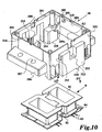
- the anchor housing 20 is shown in more detail in FIG. 10.
- the armature housing 20 is frame-like up and down open and also symmetrical to the longitudinal axis X of the magnetic core 2 is formed.
- At two each other opposite side walls 203, 204 are outside side flanges 206 with holes 207 for attaching the armature housing to the magnetic core housing educated.
- At the other two opposite each other Side walls 201, 202 are stiffening projections 211 on the outside molded, the upper side laterally downwardly projecting locking hooks 213, and the lower side of the Kodiemocken 218 is formed.
- the side walls 201, 202 and the stiffening projections 211 each have a central receiving groove 208 and 212 for the use and management of the armature 9 with AnkerdomabilitygePFuse 90, see Fig. 2, on.
- On top of the anchor housing 20 are in the side walls 203, 204 also fitting grooves 219 for Connection housing provided, as well as snap hook 205th
- the armature housing 20 is inside with of the side walls 203, 204 protruding projections 209 with contact surfaces 209 a formed at which the edge of the bobbin 8 comes to rest.
- Fig. 6 is shown schematically how the in the magnetic core housing 10th on the magnets, not shown, coil body 8 by placing the armature housing 20 on the magnetic core housing 10 through the projections 208 is held.
- the bobbin 8 is between the projections 209 of the armature housing 20 and the support webs 111, 112 of the magnetic core housing held with sufficient play, so that the bobbin even in the bolted state of the housing parts not stressed to pressure becomes.
- the bobbin 8 is also shown in Fig. 10. He is of two equal Coils made by assembling and latching the same and has pins on one or both opposite narrow sides 83 on. To the pins 83 leads on one side in the region of the coil edge an open guide channel 84 for the coil wire.
- the armature housing 20 serves to receive the guide inserts 7, see Figs. 2 and 4.
- the armature housing 20, see Fig. 10 inside formed from the bottom 217 ago with a groove-shaped bag 214, which has a central guide part 215. Center is in the bag in Longitudinal extension of a dovetail guide 216 is formed.
- the leadership assignment 7, see Fig. 9, has lateral webs 71, 70 which are upwards projecting over the middle part 74, forming a receiving region 72.
- the dovetail-shaped Engaging groove 73 is formed, with the guide insert 7 in the dovetail guide 216 in the pocket 214 of the anchor housing 20 from the bottom is inserted.
- the side bars 71 are slightly before and Together with the middle part form an engagement area that extends over the Whole length of the guide insert can extend.
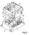
- Fig. 4 it can be seen how the guide insert 7 from the bottom is inserted into the anchor housing 20 in the pockets 214 and to the inside, i.e. to the receiving space A2, in addition to a receiving area 72 in Shape of a groove through the side bars 71, 70 forms. Furthermore, as Einschubbegrenzung for the guide insert 7 two support webs 117 of the inside of the side walls 101, 102 of the magnetic core housing 10 outgoing educated. The leadership inserts serve to guide moving Parts that protrude from the top into the anchor housing.
- connection modules 4 see FIG. 2 and FIG. 5, are in the insertion slots 110 inserted on top of the magnetic core housing. Subsequently the armature housing 20 is in the direction of arrow P2 on the magnetic core housing 10th deferred, wherein the armature housing with the stiffening protrusions 211 each between two connection modules 4 or connection module and dummy module 4a engages and sets them in position. To effect a fastening the guide members 213 of the armature housing 20, in the corresponding Intervene grooves on the adjacent sides of the connection modules 4.
Landscapes
- Physics & Mathematics (AREA)
- Electromagnetism (AREA)
- Electromagnets (AREA)
- Reciprocating, Oscillating Or Vibrating Motors (AREA)
- Switch Cases, Indication, And Locking (AREA)
- Driving Mechanisms And Operating Circuits Of Arc-Extinguishing High-Tension Switches (AREA)
Description
- Figur 1:
- eine perspektivische Darstellung des den Antriebsraum aufnehmenden erfindungsgemäß gestalteten Gehäusebereiches;
- Figur 2:
- eine Explosionsdarstellung der den Antriebsraum des elektromagnetischen Schaltgerätes bildenden Teile;
- Figur 3:
- eine Explosionsdarstellung des Magnetkerngehäuses mit Magnetkern;
- Figur 4:
- eine Explosionsdarstellung des Magnetkerngehäuses und des Ankergehäuses mit Führungseinsätzen;
- Figur 5:
- eine Explosionsdarstellung des Magnetkerngehäuses und des Ankergehäuses mit Anschlußmodulen;
- Figur 6:
- eine Aufsicht auf das Magnetkerngehäuse und Ankergehäuse mit eingesetztem Spulenkörper;
- Figur 7:
- ein Dämpfungselement;
- Figur 8:
- ein Auflager für den Magnetkern;
- Figur 9:
- den Führungseinsatz gemäß Fig. 4;
- Figur 10:
- eine Explosionsdarstellung von Ankergehäuse und Spulenkörper;
- Figur 11:
- eine Explosionsdarstellung von Bodenplatte und Leiterplatte.
Claims (15)
- Elektromagnetisches Schaltgerät, insbesondere Schütz, mit einem Kontaktraum für die beweglichen Kontakte und Festkontakte und mit einem Antriebsraum für den Magnetantrieb mit Magnetkern (2), Spule und Anker (9) zum Betätigen der Kontakte, die in einem mehrteiligen Gehäuse untergebracht sind, wobei das den Antriebsraum umfassende Gehäuse (100) aus zwei rahmenartigen ein Magnetkerngehäuse (10) und ein Ankergehäuse (20) bildenden Gehäuseteilen mit nach oben und unten offenem Aufnahmeraum (A1, A2) zusammengesetzt ist und der offene Boden des Magnetkerngehäuses (10) mittels einer an der Unterseite des Magnetkerngehäuses eingesetzten Bodenplatte (30) verschlossen ist, dadurch gekennzeichnet, daß am Magnetkerngehäuse (10) innenseitig ausgebildete Taschen (106) vorgesehen sind und in das Magnetkerngehäuse (10) von der Oberseite her der mit zwei Achsen (221, 222) ausgerüstete Magnetkern (2) mit den als Auflager (5) ausgebildeten Achsenden in die Taschen (106) eingesetzt ist und das Ankergehäuse (20) innenseitig zu den Taschen (106) des Magnetkerngehäuses (10) korrespondierende angeformte Gegenlagerflächen (210) aufweist, dergestalt, daß bei miteinander verschraubtem Magnetkerngehäuse (10) und Ankergehäuse (20) die Gegenlagerflächen (210) des Ankergehäuses (20) in die Taschen (106) des Magnetkerngehäuses (10) eingreifen und auf die Auflager (5) des Magnetkerns (2) drücken.
- Schaltgerät nach Anspruch 1, dadurch gekennzeichnet, daß innenseitig am Magnetkerngehäuse (10) seitlich des Magnetkern Auflagerstege (111, 112) für das Aufsetzen des Spulenkörpers ausgebildet sind, und das auf das Magnetkerngehäuse (10) aufgesetzte Ankergehäuse (20) innenseitig mit als Anlage für den Spulenkörper (8) dienenden Vorsprüngen (209) ausgebildet ist, und der Spulenkörper (8) zwischen den Auflagerstegen (111, 112) des Magnetkerngehäuses (10) und den Vorsprüngen (209) des Ankergehäuses (20) mit ausreichendem Spiel festgelegt ist, so daß der Spulenkörper (8) selbst nicht durch Druck beansprucht wird.
- Schaltgerät nach Anspruch 1, dadurch gekennzeichnet, daß die Auflager (5) des Magnetkerns (2) zwischen zwei elastischen Dämpfungsplatten (6) eingebettet sind, so daß bei miteinander durch Verschrauben verbundenem Magnetkerngehäuse (10) und Ankergehäuse (20) diese eine Vorspannung aufweisen.
- Schaltgerät nach Anspruch 3, dadurch gekennzeichnet, daß die Auflager (5) des Magnetkerns (2) aus einem Kunststoff und die Dämpfungsplatten (6) aus Gummi gefertigt sind.
- Schaltgerät nach Anspruch 1, dadurch gekennzeichnet, daß die Leiterplatte (3) einen wannenartigen Aufbau mit einer in Kunststoff eingegossenen Platine aufweist.
- Schaltgerät nach Anspruch 1, dadurch gekennzeichnet, daß mindestens ein Führungseinsatz (7) an der Innenwandung des Ankergehäuses (20) und/oder Magnetkerngehäuses (10) befestigbar ist.
- Schaltgerät nach Anspruch 6, dadurch gekennzeichnet, daß der Führungseinsatz (7) in seinem oberen im Ankergehäuse (20) befindlichen Bereich mit einer Führungsaufnahme (72) für bewegliche Teile, wie einer Brücke, ausgebildet ist.
- Schaltgerät nach Anspruch 5 oder 6, dadurch gekennzeichnet, daß an einander gegenüberliegenden Seiten des Ankergehäuses (20) oder Magnetkerngehäuses (10) je ein Führungseinsatz (7) mittels einer Schwalbenschwanzverbindung anbringbar ist.
- Schaltgerät nach einem der Ansprüche 5 bis 7, dadurch gekennzeichnet, daß am Ankergehäuse (20) an zwei einander gegenüberliegenden Seiten innenseitig eine nach unten offene taschenartige Nut (214) mit einem oberen mittleren Führungsteil (215) und von oben nach unten verlaufender Schwalbenschwanzführung (216) ausgebildet ist, in die der Führungseinsatz (7) von unten her mit einer am Führungseinsatz (7) ausgebildeten schwalbenschwanzförmigen Eingriffsnut (73) einschiebbar ist.
- Schaltgerät nach Anspruch 1, dadurch gekennzeichnet, daß Anschlußmodule (4, 4a) vorgesehen sind, und das Magnetkerngehäuse (10) zur Aufnahme der Anschlußmodule (4, 4a) an zwei einander gegenüberliegenden Seiten nahe dem Eckbereich auf seiner Oberseite parallel zu den Seiten verlaufende Einstecknuten (110) aufweist, die ihre Einstecköffnung innenseitig aufweisen, dergestalt, daß mit T-förmigem oder dergleichen hinterrastbarem Einstecksteg (41) ausgebildete Anschlußmodule in die Einstecknuten einsetzbar sind.
- Schaltgerät nach Anspruch 10, dadurch gekennzeichnet, daß das Ankergehäuse (20) an zwei einander gegenüberliegenden Außenseiten (201, 202) je zwei Modulaufnahmen (211) aufweist zum paßgenauen Einführen zwischen zwei auf dem Magnetkerngehäuse (10) eingesteckten Anschlußmodulen (4, 4a) bzw. Leermodulen beim Verbinden des Ankergehäuses (20) mit dem Magnetkerngehäuse (10), wodurch die Anschlußmodule bzw. Leermodule am Herausfallen gehindert sind.
- Schaltgerät nach Anspruch 11, dadurch gekennzeichnet, daß die Außenseiten (201, 202) des Ankergehäuses (20) seitliche Führungsvorsprünge, die in die Anschlußmodule eingreifen, aufweisen.
- Schaltgerät nach einem der Ansprüche 1 bis 12, dadurch gekennzeichnet, daß das Magnetkerngehäuse (10) und das Ankergehäuse (20) für ein paßgenaues Zusammensetzen im Bereich der Teilungsfuge mindestens eine Kodierpassung in Gestalt einer Nase-Nut-Passung aufweisen.
- Schaltgerät nach einem der Ansprüche 1 bis 13, dadurch gekennzeichnet, daß in den Aufnahmeraum (A2) des Ankergehäuses (20) von oben her der an einem Ankerdomaufnahmegehäuse (90) befestigte Anker (9) einsetzbar ist.
- Schaltgerät nach Anspruch 1, dadurch gekennzeichnet, daß die die Auflager (5) des Magnetkerns (2) aufnehmenden Taschen (106) am Magnetkerngehäuse (10) topfartig ausgebildet sind und auf der dem Magnetkern zugewandten Seite einen nach oben offenen Lagerschlitz (107) zum Einsetzen der Achsen des Magnetkerns (2) aufweisen.
Applications Claiming Priority (2)
| Application Number | Priority Date | Filing Date | Title |
|---|---|---|---|
| DE1998114432 DE19814432C1 (de) | 1998-03-31 | 1998-03-31 | Elektromagnetisches Schaltgerät mit einem mehrteiligen Gehäuse |
| DE19814432 | 1998-03-31 |
Publications (3)
| Publication Number | Publication Date |
|---|---|
| EP0948016A2 EP0948016A2 (de) | 1999-10-06 |
| EP0948016A3 EP0948016A3 (de) | 2000-10-11 |
| EP0948016B1 true EP0948016B1 (de) | 2005-08-31 |
Family
ID=7863135
Family Applications (1)
| Application Number | Title | Priority Date | Filing Date |
|---|---|---|---|
| EP19990105335 Expired - Lifetime EP0948016B1 (de) | 1998-03-31 | 1999-03-16 | Elektromagnetisches Schaltgerät mit einem mehrteiligen Gehäuse |
Country Status (3)
| Country | Link |
|---|---|
| EP (1) | EP0948016B1 (de) |
| CN (1) | CN1124630C (de) |
| DE (1) | DE19814432C1 (de) |
Cited By (1)
| Publication number | Priority date | Publication date | Assignee | Title |
|---|---|---|---|---|
| WO2025223800A1 (en) * | 2024-04-23 | 2025-10-30 | Eaton Intelligent Power Limited | Switching device |
Families Citing this family (9)
| Publication number | Priority date | Publication date | Assignee | Title |
|---|---|---|---|---|
| JP2004047141A (ja) * | 2002-07-09 | 2004-02-12 | Fuji Electric Holdings Co Ltd | 電磁接触器 |
| JP4321256B2 (ja) | 2003-12-22 | 2009-08-26 | オムロン株式会社 | 電磁継電器 |
| DE102004009650B3 (de) * | 2004-02-27 | 2005-07-07 | Moeller Gmbh | Schaltschütz mit Anschlussmodul zum Ansteuern des Magnetantriebes |
| KR100990267B1 (ko) | 2008-12-03 | 2010-10-26 | 엘에스산전 주식회사 | 마모 방지 수단을 갖는 전자 접촉기 |
| CN103811229B (zh) * | 2014-03-12 | 2016-01-13 | 瞿建喜 | 一种单极嵌裝式电磁开关 |
| JP7020481B2 (ja) * | 2017-03-27 | 2022-02-16 | 日立金属株式会社 | コイル部品 |
| DE102021106091A1 (de) * | 2021-03-12 | 2022-09-15 | Tdk Electronics Ag | Gehäuseanordnung |
| DE102021106112A1 (de) | 2021-03-12 | 2022-09-15 | Tdk Electronics Ag | Gehäuse für elektromechanische Komponente |
| CN116153716B (zh) * | 2022-12-14 | 2025-06-10 | 浙江兆正机电有限公司 | 接触器 |
Family Cites Families (7)
| Publication number | Priority date | Publication date | Assignee | Title |
|---|---|---|---|---|
| DE1138141B (de) * | 1958-07-29 | 1962-10-18 | Weyer & Zander K G | Formschluessige elastische Verbindung zwischen Magnetanker und Schaltbruecke eines Luftschuetzes |
| US3060355A (en) * | 1960-05-20 | 1962-10-23 | Westinghouse Electric Corp | Relay magnet suspension |
| DE1590884A1 (de) * | 1966-03-03 | 1970-12-17 | Schaltelektronik Oppach Veb K | Aus mehreren Baugruppen bestehendes elektrisches Schuetz |
| US3835425A (en) * | 1973-11-01 | 1974-09-10 | Square D Co | Electromagnetic relay with reversible switch modules |
| US4506243A (en) * | 1981-05-28 | 1985-03-19 | Mitsubishi Denki Kabushiki Kaisha | Electromagnetic contactor |
| DE4244606C2 (de) * | 1992-12-31 | 1995-08-31 | Kloeckner Moeller Gmbh | Elektromagnetisches Schaltgerät |
| DE4322648C1 (de) * | 1993-07-07 | 1994-08-18 | Siemens Ag | Gerät mit Vierbeinspule |
-
1998
- 1998-03-31 DE DE1998114432 patent/DE19814432C1/de not_active Expired - Lifetime
-
1999
- 1999-03-16 EP EP19990105335 patent/EP0948016B1/de not_active Expired - Lifetime
- 1999-03-31 CN CN 99103479 patent/CN1124630C/zh not_active Expired - Lifetime
Cited By (1)
| Publication number | Priority date | Publication date | Assignee | Title |
|---|---|---|---|---|
| WO2025223800A1 (en) * | 2024-04-23 | 2025-10-30 | Eaton Intelligent Power Limited | Switching device |
Also Published As
| Publication number | Publication date |
|---|---|
| EP0948016A2 (de) | 1999-10-06 |
| CN1124630C (zh) | 2003-10-15 |
| DE19814432C1 (de) | 1999-12-23 |
| EP0948016A3 (de) | 2000-10-11 |
| HK1022209A1 (en) | 2000-07-28 |
| CN1230759A (zh) | 1999-10-06 |
Similar Documents
| Publication | Publication Date | Title |
|---|---|---|
| EP0036027B1 (de) | Elektromagnetisches Schütz | |
| DE10030140B4 (de) | Gleitführungseinheit | |
| DE60226208T2 (de) | Modulare Struktur zum Halten von Sicherungen und modularer Sicherungshalter | |
| DE9211726U1 (de) | Elektromagnetisches Relais | |
| DE19814432C1 (de) | Elektromagnetisches Schaltgerät mit einem mehrteiligen Gehäuse | |
| DE1277440C2 (de) | Elektromagnetisch betaetigtes Schaltgeraet | |
| WO1989011726A1 (en) | Electromagnetic switching device | |
| EP0017124B1 (de) | Elektrisches Gerät, insbesondere Installationsgerät | |
| DE4244606C2 (de) | Elektromagnetisches Schaltgerät | |
| DE2537284A1 (de) | Prellfreier elektrischer schalter | |
| DE4333302A1 (de) | Elektrischer Schalter mit federnd abgestützter Schaltbrücke | |
| EP0610710B1 (de) | Vorrichtung zur lösbaren Befestigung von elektrischen Installationsgeräten | |
| DE3304096C2 (de) | Steckverbindung, insbesondere für zweiteilige Gehäuse von Steuer- und Regelgeräten | |
| DE102006053415B3 (de) | Befestigungsvorrichtung | |
| DE2711480A1 (de) | Elektromagnetisches miniaturrelais | |
| DE3908442C2 (de) | ||
| DE3441224A1 (de) | Elektromagnetisches klappankerrelais | |
| DE29521012U1 (de) | Polarisiertes elektromagnetisches Relais | |
| DE29823818U1 (de) | Elektromagnetisches Schaltgerät mit Magnetantrieb und Brückensystem | |
| DE19846219B4 (de) | Stromschalter | |
| DE3208991C2 (de) | Gehäuse für Leiterkarten | |
| DE19814431A1 (de) | Elektromagnetisches Schaltgerät mit Magnetantrieb und Brückensystem | |
| DE10244146B4 (de) | Elektromagnetisches Relais mit zwangsgeführten Kontakten | |
| WO1997042643A1 (de) | Elektromagnetisches relais | |
| DE10251455B3 (de) | Elektromagnetisches Relais |
Legal Events
| Date | Code | Title | Description |
|---|---|---|---|
| PUAI | Public reference made under article 153(3) epc to a published international application that has entered the european phase |
Free format text: ORIGINAL CODE: 0009012 |
|
| AK | Designated contracting states |
Kind code of ref document: A2 Designated state(s): CH FR IT LI SE |
|
| AX | Request for extension of the european patent |
Free format text: AL;LT;LV;MK;RO;SI |
|
| PUAL | Search report despatched |
Free format text: ORIGINAL CODE: 0009013 |
|
| AK | Designated contracting states |
Kind code of ref document: A3 Designated state(s): AT BE CH CY DE DK ES FI FR GB GR IE IT LI LU MC NL PT SE |
|
| AX | Request for extension of the european patent |
Free format text: AL;LT;LV;MK;RO;SI |
|
| 17P | Request for examination filed |
Effective date: 20010321 |
|
| AKX | Designation fees paid |
Free format text: CH FR IT LI SE |
|
| REG | Reference to a national code |
Ref country code: DE Ref legal event code: 8566 |
|
| GRAP | Despatch of communication of intention to grant a patent |
Free format text: ORIGINAL CODE: EPIDOSNIGR1 |
|
| GRAS | Grant fee paid |
Free format text: ORIGINAL CODE: EPIDOSNIGR3 |
|
| RTI1 | Title (correction) |
Free format text: ELECTROMAGNETIC SWITCHING DEVICE HAVING A MULTI-PART HOUSING |
|
| GRAA | (expected) grant |
Free format text: ORIGINAL CODE: 0009210 |
|
| AK | Designated contracting states |
Kind code of ref document: B1 Designated state(s): CH FR IT LI SE |
|
| REG | Reference to a national code |
Ref country code: CH Ref legal event code: EP |
|
| REG | Reference to a national code |
Ref country code: CH Ref legal event code: NV Representative=s name: DTS ZUERICH SCHWEIZER- UND EUROPAEISCHE PATENTANWA |
|
| REG | Reference to a national code |
Ref country code: SE Ref legal event code: TRGR |
|
| ET | Fr: translation filed | ||
| PLBE | No opposition filed within time limit |
Free format text: ORIGINAL CODE: 0009261 |
|
| STAA | Information on the status of an ep patent application or granted ep patent |
Free format text: STATUS: NO OPPOSITION FILED WITHIN TIME LIMIT |
|
| 26N | No opposition filed |
Effective date: 20060601 |
|
| REG | Reference to a national code |
Ref country code: CH Ref legal event code: PCAR Representative=s name: DTS ZUERICH; CH |
|
| REG | Reference to a national code |
Ref country code: CH Ref legal event code: PCAR Free format text: DTS ZUERICH;RESIRAIN 1;8125 ZOLLIKERBERG (CH) |
|
| REG | Reference to a national code |
Ref country code: FR Ref legal event code: PLFP Year of fee payment: 18 |
|
| REG | Reference to a national code |
Ref country code: FR Ref legal event code: PLFP Year of fee payment: 19 |
|
| REG | Reference to a national code |
Ref country code: FR Ref legal event code: PLFP Year of fee payment: 20 |
|
| PGFP | Annual fee paid to national office [announced via postgrant information from national office to epo] |
Ref country code: CH Payment date: 20180226 Year of fee payment: 20 |
|
| PGFP | Annual fee paid to national office [announced via postgrant information from national office to epo] |
Ref country code: IT Payment date: 20180219 Year of fee payment: 20 Ref country code: FR Payment date: 20180220 Year of fee payment: 20 Ref country code: SE Payment date: 20180226 Year of fee payment: 20 |
|
| REG | Reference to a national code |
Ref country code: CH Ref legal event code: PL |