EP0947899A2 - Verfahren zur Herstellung von prothetischen Oberflächen - Google Patents
Verfahren zur Herstellung von prothetischen Oberflächen Download PDFInfo
- Publication number
- EP0947899A2 EP0947899A2 EP99301866A EP99301866A EP0947899A2 EP 0947899 A2 EP0947899 A2 EP 0947899A2 EP 99301866 A EP99301866 A EP 99301866A EP 99301866 A EP99301866 A EP 99301866A EP 0947899 A2 EP0947899 A2 EP 0947899A2
- Authority
- EP
- European Patent Office
- Prior art keywords
- data set
- mold
- composite
- limb
- prosthetic
- Prior art date
- Legal status (The legal status is an assumption and is not a legal conclusion. Google has not performed a legal analysis and makes no representation as to the accuracy of the status listed.)
- Withdrawn
Links
Images


Classifications
-
- G—PHYSICS
- G01—MEASURING; TESTING
- G01S—RADIO DIRECTION-FINDING; RADIO NAVIGATION; DETERMINING DISTANCE OR VELOCITY BY USE OF RADIO WAVES; LOCATING OR PRESENCE-DETECTING BY USE OF THE REFLECTION OR RERADIATION OF RADIO WAVES; ANALOGOUS ARRANGEMENTS USING OTHER WAVES
- G01S17/00—Systems using the reflection or reradiation of electromagnetic waves other than radio waves, e.g. lidar systems
- G01S17/88—Lidar systems specially adapted for specific applications
- G01S17/89—Lidar systems specially adapted for specific applications for mapping or imaging
-
- A—HUMAN NECESSITIES
- A61—MEDICAL OR VETERINARY SCIENCE; HYGIENE
- A61F—FILTERS IMPLANTABLE INTO BLOOD VESSELS; PROSTHESES; DEVICES PROVIDING PATENCY TO, OR PREVENTING COLLAPSING OF, TUBULAR STRUCTURES OF THE BODY, e.g. STENTS; ORTHOPAEDIC, NURSING OR CONTRACEPTIVE DEVICES; FOMENTATION; TREATMENT OR PROTECTION OF EYES OR EARS; BANDAGES, DRESSINGS OR ABSORBENT PADS; FIRST-AID KITS
- A61F2/00—Filters implantable into blood vessels; Prostheses, i.e. artificial substitutes or replacements for parts of the body; Appliances for connecting them with the body; Devices providing patency to, or preventing collapsing of, tubular structures of the body, e.g. stents
- A61F2/50—Prostheses not implantable in the body
- A61F2/5044—Designing or manufacturing processes
- A61F2/5046—Designing or manufacturing processes for designing or making customized prostheses, e.g. using templates, finite-element analysis or CAD-CAM techniques
-
- A—HUMAN NECESSITIES
- A61—MEDICAL OR VETERINARY SCIENCE; HYGIENE
- A61F—FILTERS IMPLANTABLE INTO BLOOD VESSELS; PROSTHESES; DEVICES PROVIDING PATENCY TO, OR PREVENTING COLLAPSING OF, TUBULAR STRUCTURES OF THE BODY, e.g. STENTS; ORTHOPAEDIC, NURSING OR CONTRACEPTIVE DEVICES; FOMENTATION; TREATMENT OR PROTECTION OF EYES OR EARS; BANDAGES, DRESSINGS OR ABSORBENT PADS; FIRST-AID KITS
- A61F2/00—Filters implantable into blood vessels; Prostheses, i.e. artificial substitutes or replacements for parts of the body; Appliances for connecting them with the body; Devices providing patency to, or preventing collapsing of, tubular structures of the body, e.g. stents
- A61F2/50—Prostheses not implantable in the body
- A61F2/54—Artificial arms or hands or parts thereof
- A61F2/58—Elbows; Wrists ; Other joints; Hands
- A61F2/583—Hands; Wrist joints
- A61F2/586—Fingers
-
- B—PERFORMING OPERATIONS; TRANSPORTING
- B29—WORKING OF PLASTICS; WORKING OF SUBSTANCES IN A PLASTIC STATE IN GENERAL
- B29C—SHAPING OR JOINING OF PLASTICS; SHAPING OF MATERIAL IN A PLASTIC STATE, NOT OTHERWISE PROVIDED FOR; AFTER-TREATMENT OF THE SHAPED PRODUCTS, e.g. REPAIRING
- B29C33/00—Moulds or cores; Details thereof or accessories therefor
- B29C33/38—Moulds or cores; Details thereof or accessories therefor characterised by the material or the manufacturing process
- B29C33/3835—Designing moulds, e.g. using CAD-CAM
-
- B—PERFORMING OPERATIONS; TRANSPORTING
- B29—WORKING OF PLASTICS; WORKING OF SUBSTANCES IN A PLASTIC STATE IN GENERAL
- B29C—SHAPING OR JOINING OF PLASTICS; SHAPING OF MATERIAL IN A PLASTIC STATE, NOT OTHERWISE PROVIDED FOR; AFTER-TREATMENT OF THE SHAPED PRODUCTS, e.g. REPAIRING
- B29C39/00—Shaping by casting, i.e. introducing the moulding material into a mould or between confining surfaces without significant moulding pressure; Apparatus therefor
- B29C39/02—Shaping by casting, i.e. introducing the moulding material into a mould or between confining surfaces without significant moulding pressure; Apparatus therefor for making articles of definite length, i.e. discrete articles
- B29C39/10—Shaping by casting, i.e. introducing the moulding material into a mould or between confining surfaces without significant moulding pressure; Apparatus therefor for making articles of definite length, i.e. discrete articles incorporating preformed parts or layers, e.g. casting around inserts or for coating articles
-
- B—PERFORMING OPERATIONS; TRANSPORTING
- B29—WORKING OF PLASTICS; WORKING OF SUBSTANCES IN A PLASTIC STATE IN GENERAL
- B29C—SHAPING OR JOINING OF PLASTICS; SHAPING OF MATERIAL IN A PLASTIC STATE, NOT OTHERWISE PROVIDED FOR; AFTER-TREATMENT OF THE SHAPED PRODUCTS, e.g. REPAIRING
- B29C41/00—Shaping by coating a mould, core or other substrate, i.e. by depositing material and stripping-off the shaped article; Apparatus therefor
- B29C41/02—Shaping by coating a mould, core or other substrate, i.e. by depositing material and stripping-off the shaped article; Apparatus therefor for making articles of definite length, i.e. discrete articles
- B29C41/04—Rotational or centrifugal casting, i.e. coating the inside of a mould by rotating the mould
-
- G—PHYSICS
- G05—CONTROLLING; REGULATING
- G05B—CONTROL OR REGULATING SYSTEMS IN GENERAL; FUNCTIONAL ELEMENTS OF SUCH SYSTEMS; MONITORING OR TESTING ARRANGEMENTS FOR SUCH SYSTEMS OR ELEMENTS
- G05B19/00—Program-control systems
- G05B19/02—Program-control systems electric
- G05B19/42—Recording and playback systems, i.e. in which the program is recorded from a cycle of operations, e.g. the cycle of operations being manually controlled, after which this record is played back on the same machine
- G05B19/4202—Recording and playback systems, i.e. in which the program is recorded from a cycle of operations, e.g. the cycle of operations being manually controlled, after which this record is played back on the same machine preparation of the program medium using a drawing, a model
- G05B19/4207—Recording and playback systems, i.e. in which the program is recorded from a cycle of operations, e.g. the cycle of operations being manually controlled, after which this record is played back on the same machine preparation of the program medium using a drawing, a model in which a model is traced or scanned and corresponding data recorded
-
- A—HUMAN NECESSITIES
- A61—MEDICAL OR VETERINARY SCIENCE; HYGIENE
- A61F—FILTERS IMPLANTABLE INTO BLOOD VESSELS; PROSTHESES; DEVICES PROVIDING PATENCY TO, OR PREVENTING COLLAPSING OF, TUBULAR STRUCTURES OF THE BODY, e.g. STENTS; ORTHOPAEDIC, NURSING OR CONTRACEPTIVE DEVICES; FOMENTATION; TREATMENT OR PROTECTION OF EYES OR EARS; BANDAGES, DRESSINGS OR ABSORBENT PADS; FIRST-AID KITS
- A61F2/00—Filters implantable into blood vessels; Prostheses, i.e. artificial substitutes or replacements for parts of the body; Appliances for connecting them with the body; Devices providing patency to, or preventing collapsing of, tubular structures of the body, e.g. stents
- A61F2/02—Prostheses implantable into the body
- A61F2/30—Joints
- A61F2002/30001—Additional features of subject-matter classified in A61F2/28, A61F2/30 and subgroups thereof
- A61F2002/30667—Features concerning an interaction with the environment or a particular use of the prosthesis
- A61F2002/30708—Means for distinguishing between left-sided and right-sided devices, Sets comprising both left-sided and right-sided prosthetic parts
-
- A—HUMAN NECESSITIES
- A61—MEDICAL OR VETERINARY SCIENCE; HYGIENE
- A61F—FILTERS IMPLANTABLE INTO BLOOD VESSELS; PROSTHESES; DEVICES PROVIDING PATENCY TO, OR PREVENTING COLLAPSING OF, TUBULAR STRUCTURES OF THE BODY, e.g. STENTS; ORTHOPAEDIC, NURSING OR CONTRACEPTIVE DEVICES; FOMENTATION; TREATMENT OR PROTECTION OF EYES OR EARS; BANDAGES, DRESSINGS OR ABSORBENT PADS; FIRST-AID KITS
- A61F2/00—Filters implantable into blood vessels; Prostheses, i.e. artificial substitutes or replacements for parts of the body; Appliances for connecting them with the body; Devices providing patency to, or preventing collapsing of, tubular structures of the body, e.g. stents
- A61F2/50—Prostheses not implantable in the body
- A61F2002/5001—Cosmetic coverings
-
- A—HUMAN NECESSITIES
- A61—MEDICAL OR VETERINARY SCIENCE; HYGIENE
- A61F—FILTERS IMPLANTABLE INTO BLOOD VESSELS; PROSTHESES; DEVICES PROVIDING PATENCY TO, OR PREVENTING COLLAPSING OF, TUBULAR STRUCTURES OF THE BODY, e.g. STENTS; ORTHOPAEDIC, NURSING OR CONTRACEPTIVE DEVICES; FOMENTATION; TREATMENT OR PROTECTION OF EYES OR EARS; BANDAGES, DRESSINGS OR ABSORBENT PADS; FIRST-AID KITS
- A61F2/00—Filters implantable into blood vessels; Prostheses, i.e. artificial substitutes or replacements for parts of the body; Appliances for connecting them with the body; Devices providing patency to, or preventing collapsing of, tubular structures of the body, e.g. stents
- A61F2/50—Prostheses not implantable in the body
- A61F2/5044—Designing or manufacturing processes
- A61F2/5046—Designing or manufacturing processes for designing or making customized prostheses, e.g. using templates, finite-element analysis or CAD-CAM techniques
- A61F2002/5053—Designing or manufacturing processes for designing or making customized prostheses, e.g. using templates, finite-element analysis or CAD-CAM techniques using a positive or a negative model, e.g. casting model or mould
-
- A—HUMAN NECESSITIES
- A61—MEDICAL OR VETERINARY SCIENCE; HYGIENE
- A61F—FILTERS IMPLANTABLE INTO BLOOD VESSELS; PROSTHESES; DEVICES PROVIDING PATENCY TO, OR PREVENTING COLLAPSING OF, TUBULAR STRUCTURES OF THE BODY, e.g. STENTS; ORTHOPAEDIC, NURSING OR CONTRACEPTIVE DEVICES; FOMENTATION; TREATMENT OR PROTECTION OF EYES OR EARS; BANDAGES, DRESSINGS OR ABSORBENT PADS; FIRST-AID KITS
- A61F2250/00—Special features of prostheses classified in groups A61F2/00 - A61F2/26 or A61F2/82 or A61F9/00 or A61F11/00 or subgroups thereof
- A61F2250/0058—Additional features; Implant or prostheses properties not otherwise provided for
- A61F2250/0084—Means for distinguishing between left-sided and right-sided devices; Sets comprising both left-sided and right-sided prosthetic parts
-
- B—PERFORMING OPERATIONS; TRANSPORTING
- B29—WORKING OF PLASTICS; WORKING OF SUBSTANCES IN A PLASTIC STATE IN GENERAL
- B29C—SHAPING OR JOINING OF PLASTICS; SHAPING OF MATERIAL IN A PLASTIC STATE, NOT OTHERWISE PROVIDED FOR; AFTER-TREATMENT OF THE SHAPED PRODUCTS, e.g. REPAIRING
- B29C33/00—Moulds or cores; Details thereof or accessories therefor
- B29C33/38—Moulds or cores; Details thereof or accessories therefor characterised by the material or the manufacturing process
- B29C33/3842—Manufacturing moulds, e.g. shaping the mould surface by machining
- B29C33/3857—Manufacturing moulds, e.g. shaping the mould surface by machining by making impressions of one or more parts of models, e.g. shaped articles and including possible subsequent assembly of the parts
- B29C2033/3871—Manufacturing moulds, e.g. shaping the mould surface by machining by making impressions of one or more parts of models, e.g. shaped articles and including possible subsequent assembly of the parts the models being organic material, e.g. living or dead bodies or parts thereof
-
- B—PERFORMING OPERATIONS; TRANSPORTING
- B29—WORKING OF PLASTICS; WORKING OF SUBSTANCES IN A PLASTIC STATE IN GENERAL
- B29C—SHAPING OR JOINING OF PLASTICS; SHAPING OF MATERIAL IN A PLASTIC STATE, NOT OTHERWISE PROVIDED FOR; AFTER-TREATMENT OF THE SHAPED PRODUCTS, e.g. REPAIRING
- B29C41/00—Shaping by coating a mould, core or other substrate, i.e. by depositing material and stripping-off the shaped article; Apparatus therefor
- B29C41/02—Shaping by coating a mould, core or other substrate, i.e. by depositing material and stripping-off the shaped article; Apparatus therefor for making articles of definite length, i.e. discrete articles
- B29C41/22—Making multilayered or multicoloured articles
-
- G—PHYSICS
- G05—CONTROLLING; REGULATING
- G05B—CONTROL OR REGULATING SYSTEMS IN GENERAL; FUNCTIONAL ELEMENTS OF SUCH SYSTEMS; MONITORING OR TESTING ARRANGEMENTS FOR SUCH SYSTEMS OR ELEMENTS
- G05B2219/00—Program-control systems
- G05B2219/30—Nc systems
- G05B2219/49—Nc machine tool, till multiple
- G05B2219/49005—Map 2-D pattern on 3-D
-
- G—PHYSICS
- G05—CONTROLLING; REGULATING
- G05B—CONTROL OR REGULATING SYSTEMS IN GENERAL; FUNCTIONAL ELEMENTS OF SUCH SYSTEMS; MONITORING OR TESTING ARRANGEMENTS FOR SUCH SYSTEMS OR ELEMENTS
- G05B2219/00—Program-control systems
- G05B2219/30—Nc systems
- G05B2219/49—Nc machine tool, till multiple
- G05B2219/49007—Making, forming 3-D object, model, surface
-
- Y—GENERAL TAGGING OF NEW TECHNOLOGICAL DEVELOPMENTS; GENERAL TAGGING OF CROSS-SECTIONAL TECHNOLOGIES SPANNING OVER SEVERAL SECTIONS OF THE IPC; TECHNICAL SUBJECTS COVERED BY FORMER USPC CROSS-REFERENCE ART COLLECTIONS [XRACs] AND DIGESTS
- Y10—TECHNICAL SUBJECTS COVERED BY FORMER USPC
- Y10S—TECHNICAL SUBJECTS COVERED BY FORMER USPC CROSS-REFERENCE ART COLLECTIONS [XRACs] AND DIGESTS
- Y10S264/00—Plastic and nonmetallic article shaping or treating: processes
- Y10S264/30—Use of anatomy in making a mold or using said mold
Definitions
- This invention relates to methods for reproducing a three-dimensional surface, and more particularly to methods for making surfaces for use with prosthetic devices, such as gloves resembling hands, feet, fingers, and other similar articles.
- One of the original techniques for making a prosthetic surface included making a plaster cast of a human limb that could be used to manufacture an artificial one. This method of manufacture had many drawbacks, including the appearance of a line in the artificial limb corresponding to the junction between the two halves of the mold. Moreover, the ridges and depressions that normally make up the surface of the limb, such as the ones that form fingerprints, were substantially eliminated in the manufacturing process because the plaster cast was not capable of capturing all of the detail that makes up the surface.
- a patient may desire one or more superficial differences between a left and right limb (such as the appearance of a birthmark or mole). These differences can be difficult to reliably incorporate in the reversed glove because they are usually sculpted into the glove mold. However, the quality of the sculpted mold strongly depends upon the skill and artistry of the sculptor, making this process unreliable at best.
- a method for reproducing a three-dimensional (hereinafter, "3D") object surface includes (1) identifying a real object surface, (2) acquiring at least a 3D data set with a 3D surface imaging device, (3) acquiring at least a two-dimensional (hereinafter, "2D") data set using a second surface imaging device with a surface resolution of at least about 0.1 mm 2 , (4) synthesizing a 3D composite data set by orienting a first virtual image of the first data set and a second virtual image of the second data set to form a composite virtual image that corresponds to the composite data set, and (5) making a reproduction of the object surface with the composite data set.
- Orientation of the virtual images is relative to each other and without substantial loss of surface resolution.
- a method for making a prosthetic skin for covering a prosthetic device includes (1) acquiring at least a first data set with a surface imaging device having a surface resolution of at least about 0.1 mm 2 ; (2) synthesizing a 3D composite data set from the first data set without substantial loss of the surface resolution; (3) providing the composite data set to a digitally controlled fabrication device; (4) fabricating a mold with the fabrication device using the composite data set, and (5) fabricating the prosthetic skin with the mold.
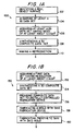
- FIG. 1A is a flow chart of steps for carrying out one illustrative embodiment of a method according to this invention for making a reproduction of a three-dimensional surface of an object.
- FIG. 1B is a flow chart of steps for carrying out another illustrative embodiment of a method according to this invention for making a prosthetic skin for covering a prosthetic device.
- FIG. 2 shows four simplified data sets that are being oriented with respect to each other to synthesize a composite data set according to this invention.
- FIG. 3 shows a simplified virtual image that corresponds to the composite data set synthesized using the four data sets shown in FIG. 2 according to this invention.
- FIGS. 4A-4C show simplified longitudinal cross-sectional views of three images of molds having different thicknesses for use in making a prosthetic skin of a finger according to this invention.
- the thicknesses of the images of the molds are exaggerated relative to the size of the finger to make certain features of the mold more visible.
- FIG. 5 shows a simplified longitudinal cross-sectional view of an illustrative mold fabricated according to this invention.
- FIG. 6 shows a simplified longitudinal view, partly in section, of the illustrative mold shown in FIG. 5 before full investment according to this invention.
- FIG. 1A is a flow chart of steps of method 100 according to this invention for reproducing a 3D object surface.
- Method 100 includes identifying a real object surface in step 102, acquiring at least a 3D data set with a 3D surface imaging device in step 104, acquiring at least a 2D data set using a second surface imaging device with a surface resolution of at least about 0.1 mm 2 in step 106, synthesizing a 3D composite data set by orienting a first virtual image of the first data set and a second virtual image of the second data set to form a composite virtual image that corresponds to the composite data set in step 108, and making a reproduction of the object surface with the composite data set in step 110.
- Orientation of the virtual images is relative to each other and without substantial loss of surface resolution.
- a real object is identified.
- a preferred real object for use with this invention is a human limb, in which case the surface of the object is the skin and nails that cover the limb.
- a limb may be an arm or a leg, or any part thereof.
- the surface of the finger would include a relatively elastic skin portion and a relatively rigid finger nail portion.
- the surface would include, in addition to the elastic skin that covers most of the hand, four rigid finger nails and a rigid thumb nail. Because the texture and hardness of skin and nails are so different, it is often desirable to make these components separately. Also, these differences may mandate that the nail and skin portions be characterized with different surface imaging devices.
- step 102 preferably includes interviewing the patient to ascertain any financial constraints, determining the level of surface resolution desired in the final prosthetic device or surface, and establishing cosmetic details that the patient may wish to have included on the surface prosthetic device.
- step 104 at least a 3D data set is acquired.
- the 3D data set depicts the 3D shape of the surface and is acquired with a 3D imaging device.
- Some of the 3D imaging devices that can be used according to this invention are sold by Cyberware, Inc., of Monterey, California (available under model no. 3030), Digibotics, Inc., of Austin, Texas (available under the trademark Digibot II®), Laser Design, Inc., of Minneapolis, Minnesota (available under the trademark Surveyor® 3D Laser Digitizing System), and Real 3D, of Orlando, Florida (available under the trademark RealScan 3DTM).
- These 3D imaging devices are laser-based measuring devices and stereoscopic measuring devices, but other devices based on different technology (such as polarization and acoustic technologies) may also be used in accordance with this invention.
- a 2D data set is acquired having a surface resolution of at least about 0.1 mm 2 .
- surface resolution is the surface area of a single pixel, which is a discrete element that, when combined with other pixels, form an image.
- a surface resolution of 0.1 mm 2 can be formed by a square pixel having sides of (0.1) 1 ⁇ 2 mm each.
- a surface resolution of 0.1 mm 2 can be formed by a rectangular pixel having sides of 0.25 mm and 0.4 mm.
- the surface resolution of the image is better than 0.1 mm 2 , that is the area of each pixel of the image is smaller than 0.1 mm 2 .
- a surface resolution of 0.05 mm 2 is preferred.
- Acquiring the 2D data set in step 106 may involve photographing the object with a digital camera so that the data set at least has gray scale information (e.g., a digital black and white photograph).
- the 2D data set may also contain color information (e.g., a digitized color photograph).
- the 2D data set acquired in step 106 is a two step process: (1) photographing the object with an analog camera to create an analog photograph and (2) digitizing the analog photograph to create a 2D data set representing the analog photograph.
- the 2D data set should at least include gray scale information, but may include color information.
- the 2D data set may be acquired in other ways.
- a first way includes making a drawing by an artist and digitizing that drawing with an imaging device to obtain an accurate 2D data set that represents the drawing.
- a second way includes making a projected outline by tracing the object and digitizing the outline to obtain a 2D data set that represents that outline. The difference between an outline and a drawing is that an outline merely describes the boundary or shape of the object, while a drawing contains more, such as surface detail.
- Yet another way to acquire a 2D data set in accordance with this invention involves measuring the object with a tape measure to obtain at least one measurable dimension, such as a length or a circumference of the object.
- the tape is useful to confirm that at least one actual physical dimension of the composite virtual image is accurate.
- Acquiring data sets in steps 104 and 106 can be direct or indirect.
- Direct data acquisition involves accumulating a data set directly from a real surface, such as a hand.
- Indirect data acquisition involves at least three steps: (1) building a negative mold of the object surface using a room temperature vulcanization technique; (2) building a positive model of the object surface using the negative mold; and (3) accumulating a data set depicting the positive model surface. If accumulating the data set depends on the reflectivity of the object surface (i.e., the real surface or the positive mold surface), a method according to a further aspect of this invention includes depositing a highly reflective coating on that surface before accumulating the 2D or 3D data sets.
- a highly reflective coating according to this invention may include zinc or titanium oxide.
- the negative mold may be built by impressing an object (e.g., a hand) in a high-resolution moldable material that substantially preserves the surface details of the object.
- a high-resolution material is a room temperature vulcanization ("RTV") molding material, such as a silicone material available under model No. 3110, sold by the Dow Corning Corporation, of Midland, Michigan.
- RTV room temperature vulcanization
- an alginate may be used.
- each of steps 104 and 106 can involve acquiring two or more data sets each. That is, step 104 may involve acquiring two or more 3D data sets and combining them in step 108 to form a composite 3D data set.
- multiple 2D data sets can be used to characterize the surface of the object. For example, if the object being reproduced is a hand, a separate 2D data set can be used to characterize each finger nail, finger print, knuckle, and palm print (see, e.g., FIG. 2).
- One reason for acquiring multiple data sets is to ensure that a proper level of detail is obtained for the entire 3D surface being reproduced.
- the number of 2D and 3D data sets acquired in steps 104 and 106 depends on the resolution of the surface imaging devices available and any financial constraints determined in step 102.
- a 3D composite data set is synthesized by orienting a first virtual image of the first data set and a second virtual image of the second data set to form a composite virtual image.
- the orientation of the first and second virtual images is performed relative to each other and is accomplished without a substantial loss of surface resolution.
- Synthesis of the composite data set may be performed with conventional 3D data editing software (such as the ones sold by NewTek, of San Antonio, Texas (available under the trademark LightWave 3D®), Cyberware, Inc., of Monterey, California (available under the trademarks CyDir Digitizing Environment®, CyClice IGES Slicing Software®, CySurf Surfacing Software®, and CySculpt Sculpting Software®).
- Synthesis of the composite data set in step 108 is performed by orienting first and second virtual images.
- the first and second virtual images correspond to the 2D and 3D data sets, respectively, and are used to create a composite virtual image.
- Synthesis preferably take place in a highly interactive and flexible environment so that the composite image, and corresponding composite data set, can be edited in stages from multiple perspectives until a final composite data set is created.
- Synthesis at least includes combining two data sets to form a composite data set, preferably by seamlessly draping a 2D data over a 3D data set. This process is sometimes referred to as "bump mapping.”
- Synthesis may further include reversing one or more data sets and creating data subsets.
- FIG. 2 shows four data sets that may be used to synthesize a composite data set according to step 108 of this invention.
- First virtual image 210 corresponds to a first 3D data set that depicts the general 3D shape of a finger. In addition to depicting the general shape of the finger, image 210 may contain substantial texture and color information.
- Second virtual image 220 corresponds to a 2D data set that includes one cosmetic detail: birthmark 222. Of course, image 220 may also include other cosmetic details, including an erasure of an undesirable surface feature.
- Third virtual image 230 corresponds to a 2D data set that includes surface texture 232 over the length of the finger. The surface texture can be obtained from a black and white photograph as described above.
- Fourth virtual image 240 corresponds to a 2D data set that includes additional surface features near the tip of the finger, including finger nail 242 and skin folds 244. The surface features contained in virtual image 240 may also be obtained from a photograph of the finger.
- FIG. 3 shows a composite virtual image 250 that contains substantially all of the information shown in virtual images 210, 220, 230, and 240. Additional data sets may be needed to define or enhance a finger print on the other side of the finger. In a preferred embodiment, orientation of the virtual images is performed while viewing them on a visual display device, including a virtual reality device. Also, it should be clear to one of ordinary skill in the art that the process of synthesizing a composite data set by overlaying multiple data sets, as shown by FIGS. 2 and 3, can be performed iteratively until a satisfactory composite image, and thereby composite data set, is synthesized.
- This may involve acquiring additional data sets at any time during the process according to this invention and incorporating them into a first or subsequent iteration of a synthesized composite data set.
- the ability to quickly create multiple iterations of virtual images before manufacturing means that development costs are reduced and reproduction quality is improved.
- the virtual image may be an accurate representation of the real object being measured, that virtual image may be modified, or enhanced, with one or more cosmetic details desired by modifying a target data set.
- a target data set may be any of the data sets used in accordance with this invention, including the 3D data set, the 2D data set, and the composite data set and/or subset.
- a cosmetic detail may be a kinetic detail, an authentic detail, or a desired detail.
- a kinetic detail is a surface feature that results when the real object moves, but does not appear in any of the 3D or 2D data sets.
- An example of a kinetic detail is a skin fold at a wrist that only appears when the wrist is in a bent position.
- An authentic detail is a surface feature that actually appeared on the object being replaced but is no longer available for imaging. For example, if a patient was missing a right arm that had a birthmark, a reproduction can be made according to this invention by acquiring data depicting the left arm without a birthmark, synthesizing a composite data set by reversing the left arm data and adding a birthmark to it, and making a right arm prosthetic device that includes the birthmark.
- the prosthetic device would be substantially the same as the left arm, but would include a birthmark.
- a blemish such as a scar, may be removed from a data set by replacing the data that define the blemish with new data that do not contain the blemish.
- birthmarks and scars are examples of authentic details according to this invention.
- desired detail is a surface feature that has no real basis, but is nonetheless desired.
- desired details may be birthmarks, tattoos, hair, and freckles.
- synthesis of a composite data set in step 108 may include reversing a data set, which involves calculating a new data set that depicts a mirror image of an original data set.
- Most conventional 3D imaging software can do this, including most of the 3D imaging software packages listed above.
- it makes no difference whether reversal occurs before or after a composite data set is created. For example, if the real object being copied is a right thumb, the 3D data set would depict the general shape of the thumb and the 2D data set would depict the thumb texture, color and other surface features, such as a thumb print.
- the composite data set can be synthesized by combining the 2D and 3D data sets before reversing them, or by reversing the 2D and 3D data sets before combining them. In either case, the composite data set that results can be used to make a reversed reproduction of the real object surface.
- a reversed data set for making a prosthetic device is an important aspect of this invention.
- Conventional techniques for making a prosthetic device require physical reversal of a mold of a counterpart limb.
- mold reversal may involve cutting the mold into parts and reattaching them in a reversed orientation, forming seams and other undesirable surface effects that must be dealt with after a prototype of the prosthetic device is made.
- Mold reversal is usually slow, labor intensive, and costly. By reversing a data set before making a mold, these disadvantages are largely eliminated.
- a composite data subset may also be synthesized in step 108.
- a composite data subset is any data set depicting any portion of the surface of a composite virtual image.
- a subset may be synthesized by selecting a portion of the surface of a virtual composite image and then creating the composite data subset, such as by storing the data that correspond to that portion.
- a subset may be created directly from a 2D or a 3D data set acquired from a patient or generated from a collection of prototypes.
- the composite data subset is preferably separately manipulatable from the composite data set.
- An example of a composite data subset is one that depicts a finger nail.
- a left hand prosthesis may have seven separately defined surfaces that correspond to seven composite data subsets.
- a first surface may correspond to a reversed image of a patient's right hand
- a second surface may correspond to the patient's left wrist stump against which the prosthesis will fit
- five additional surfaces may correspond to one thumb nail and four finger nails. Because composite data subsets are separate entities, each corresponding surface can be made separately with different materials if desired.
- the composite data set and/or subset is calibrated by comparing a measurable dimension of the real object with the same dimension of the composite set or subset.
- a measurable dimension might be a circumference of the finger at a knuckle.
- the circumference of the finger at the knuckle can be measured directly with a tape measure. That measured circumference may be used to calibrate the circumference of the respective knuckle of a composite virtual image. If a circumference of the composite virtual image is too large or small, the composite data set can be reduced or enlarged, respectively, so that the virtual image is properly calibrated and accurately represents the real or reversed object.
- Synthesis of the composite data set in step 108 may further include increasing a contrast level of a data set.
- the contrast level of a data set represents the degree of difference between the light and dark pixels of an image. So, if every pixel of a 2D image is assigned a value between 1 and 255, an image with relatively few pixels in the middle of that range would have a higher contrast level than an image with a relatively large number of pixels in the middle of that range.
- the contrast level of the first data set, second data set, and/or the composite data set or subset can be increased by deleting a middle portion of a gray scale associated with the data.
- the contrast level of the composite data set is preferably made substantially uniform over the surface of the composite image. For example, if the 3D data set has a low noise level and the 2D data set has a relatively high noise level, the contrast level of one or both of these data sets may be modified before being synthesized into a composite data set. Alternatively, the contrast level of any portion of the composite data set may be modified as desired.
- mold information is added to the composite data set.
- Mold information specifies the structure and thickness of the mold used to fabricate a reproduction according to this invention.
- adding mold information includes orienting a matrix of virtual structural elements relative to the virtual composite image. Because mold material is generally expensive, it is desirable that the mold be thin to conserve material, but thick enough to support the lining of the mold and the reproduction during fabrication.
- FIGS. 4A-4C show cross-sectional areas of three virtual composite images 410, 420, and 430, respectively, of finger mold cavity 400.
- the thicknesses of the mold images are exaggerated relative to the size of the finger to make certain features of the mold more visible.
- FIG. 4A shows finger mold cavity 400 surrounded by a relatively thin layer of structural elements 412.
- FIGS. 4B and 4C show finger mold cavity 400 surrounded by successively thicker layers of structural elements 422 and 432, respectively.
- the mold thickness is preferably between about 1.0 mm and about 10.0 mm, and most preferably about 2.0 mm.
- Structural elements 412, 422, and 433 shown in FIGS. 4A-4C are substantially hollow to further conserve mold material.
- the structural elements are preferably tubular and have a polygonal cross-sectional area (e.g., hexagonal), to form a honeycomb-like structure.
- the cross-sectional areas of the structural elements may be any shape, including elliptical, if desired.
- the desired orientation of the tubular structures that make up the mold depends on the viscosity of the material used to invest the mold.
- the molds shown in FIGS. 4A-4C have tubular elements with open ends oriented upward to prevent a low viscosity investing material from leaking out before it hardens.
- Hexagonally shaped cross-sections 414, 424, and 434 of structural elements 412, 422, and 432 are shown at the bottom of FIGS. 4A-4C, respectively.
- synthesizing in step 108 preferably includes amending the composite data set so that a portion of the composite virtual image surface virtually conforms to a different virtual surface.
- an amendment of the composite data set might be necessary to ensure that the device or skin comfortably conforms to a stump of a missing limb. Because the composite data set can be accurately amended according to this invention before a prosthetic device is made, the device has a higher likelihood of fitting the patient, without multiple iterations. Because the iterative process is the most expensive and time consuming part of a conventional manufacturing process, amendment of the composite data set before fabrication is very desirable.
- step 110 the final step of method 100, a reproduction is actually manufactured.
- Any available method can be used according to this invention, including using any of the mold-based fabrication techniques discussed below and other techniques that are not mold-based, such as a high-resolution milling techniques.
- FIG. 1B is a flow chart of steps of method 150 according to another aspect of the present invention for making a prosthetic skin.
- the method includes acquiring at least a first data set with a surface imaging device having a surface resolution of at least about 0.1 mm 2 in step 152; synthesizing a 3D composite data set from the first data set without substantial loss of the surface resolution in step 154; providing the composite data set to a digitally controlled fabrication device in step 156; fabricating a mold with a fabrication device using the composite data set in step 158, and fabricating the prosthetic skin with the mold in step 160.
- step 152 at least a first data set is acquired with a surface imaging device.
- the first data set depicts the surface of an original limb and has a surface resolution of at least about 0.1 mm 2 .
- any surface imaging device with sufficient surface resolution may be used to acquire the first data set, including 2D and 3D surface imaging devices.
- the original limb may be the missing body part being replaced, such as when a patient is preparing for an impending amputation.
- the original limb may be a counterpart of the missing limb, in which case this method would include reversing the data set so that the prosthetic skin will correspond to the missing limb.
- the prosthetic device corresponds to a right index finger
- the counterpart would be the left index finger
- the prosthetic skin would be the outer layer of the prosthetic device.
- the original limb may not even be the patient's, such as when a patient is missing both arms. In that case, the first data set can be acquired from an arm of another person of desirable size and shape.
- a 3D composite data set is synthesized from the first data set.
- synthesis may result in a composite data set that is reversed relative to the first data set.
- the 3D composite data set may be synthesized by bump mapping, or embossing, a 3D data set with a high resolution 2D data set, or by any other technique that combines two or more data sets.
- Synthesis may also include processing a 3D composite data set by adding one or more cosmetic details to the first data set.
- the surface resolution of the first data set according to this aspect of the invention must be substantially maintained in the composite data set.
- Synthesis of a 3D composite data set in step 154 should also include adding mold information as described above.
- a digitally controlled fabrication device is any fabrication apparatus that can accept as input a data set that depicts the prosthetic skin and can make a mold of the skin.
- Examples of digitally controlled fabrication devices that can be used according to this invention include, but are not limited to, fused deposition modeling devices, stereo lithographic devices, 3D electroforming systems, laminated object manufacturing systems, solid ground curing devices, and 3D printing devices.
- FIG. 5 shows a longitudinal cross-section of a preferred embodiment of a mold fabricated according to this invention.
- Mold 500 preferably includes three components: lining 510, matrix of structural elements 520, and investing material 530.
- Inner surface 511 of lining 510 is the portion of mold 500 that contains the high resolution information of the composite data set that is used to make a prosthetic skin.
- Lining 510 may be any high resolution molding material, such as epoxy.
- One type of epoxy that may be used in accordance with this invention is available under model No. SL5195, sold by the Ciba Speciality Chemicals Corporation, of Los Angeles, California.
- the material used to make the mold, including the lining must be capable of withstanding the temperatures used to cure the prosthetic material.
- matrix 520 preferably includes multiple tubular elements that can be invested, or filled, with investing material 530.
- FIG. 6 shows a planar view of mold 500 before it is fully invested.
- Upper portion 550 of mold 500 shows the honeycomb structure formed by matrix 520 before being filled with investing material.
- Lower portion 540 of mold 500 shows the outer surface of the mold after the honeycomb structure is filled with investing material.
- the negative mold fabricated in step 158 may be fabricated directly or indirectly. Indirect fabrication involves fabricating a positive mold, such as with a polymer wax material, and then fabricating a negative mold from the positive mold.
- a positive mold such as with a polymer wax material
- a negative mold from the positive mold.
- One device capable of fabricating a positive mold with a polymer wax material is available under the trademark Acturn 2100® Modeler, sold by 3D Designs, of Valencia, California.
- the material used to fabricate the negative mold is an epoxy, a phenolic resin, silicone, or an electroformed metal.
- direct fabrication of a negative mold can include building a matrix of hollow structural elements that substantially conform to the outer surface of the prosthetic device to be made and investing the matrix with a matrix investing material.
- the matrix investing material is a metal-epoxy resin, but can be any liquid capable of hardening in the matrix and capable of withstanding the temperatures used to cure the skin in step 160.
- a prosthetic skin may be fabricated by coating a lining of the mold with at least one coat of silicone material.
- the coat may be a single thick coat or any number of thinner coats that together form a coat of desired thickness.
- the coat will include a first surface that substantially contacts the lining of the mold and a second surface that does not substantially contact the lining.
- Silicone material (such as the one sold under model No. Med. 6410 by Nu-Sil Technology of Carpinteria, California, or any other silicone material having substantially similar physical properties) is a preferred prosthetic material, however, any other material capable of providing a high resolution reproduction of the lining surface may be used.
- the coating process preferably includes at least four steps -- depositing, degassing, drying, and curing the material.
- Depositing the material may include pouring or spraying the material in liquid form onto the lining of the mold.
- Degassing involves removing volatile gases, including organic solvents, that normally are emitted by the material during hardening.
- Degassing may be achieved by applying a vacuum to the material before or after the material is deposited on the lining of the mold. If degassing is performed before the mold is coated, the vacuum may be applied to the vessel containing the material. If degassing is performed after the mold is coated, a vacuum may be applied through a port of the mold.
- the strength of the vacuum is not critical, but preferably less then about 30 bars.
- a prosthetic material such as silicone
- it may be dried while the mold is rotated. Rotation of the mold causes the material to flow evenly across the surface of the mold so that the prosthetic skin can harden with a substantially uniform thickness.
- the material may be cured, such as by heating it to a temperature above room temperature.
- the mold must be capable of withstanding the temperature used to cure the prosthetic material.
- the preferred curing temperature is less than about 400°F, and most preferably less than about 375°F.
- the coat of silicone material includes two or more constituent coats
- those constituent coats may have different compositions.
- the silica concentration of one coat may be different from the concentration of another coat. So, if the skin includes two coats, the first coat, which contacts the mold lining, can have a first concentration of silica, and the second coat, which does not contact the mold lining, can have a second concentration of silica greater than the first coat.
- One reason that it may be desirable to increase the concentration of silica in the second coat is that a high concentration of silica may improve the bond between the skin and the material used to fill the prosthetic skin, especially when the fill material is silicone-based.
- Another method of improving that bond is to roughen the surface. Some of the possible ways that the surface may be roughened include abrading, etching, brushing, or sandblasting the surface.
- the method according to one aspect of the invention includes removing the skin from the mold and finishing the skin by adding color to the inner surface of the skin, such as by painting it.
- the inner surface of the skin refers to the surface of the prosthetic skin that faces toward the inside of the prosthetic device.
- the step of adding color to the inner surface may include adding any naturally occurring feature (e.g., freckles) or artificial feature (e.g., a tattoo).
- the method according to this invention may include inserting an armature (e.g., a structural element) into the skin and filling the skin with a fill material, such as silicone or urethane foam.
- an armature e.g., a structural element
- a fill material such as silicone or urethane foam.
- a method for reproducing a 3D surface such as a prosthetic skin.
- the method involves acquiring at least one data set having a surface resolution of at least about 0.1 mm 2 , synthesizing a 3D composite data set by orienting an image that corresponds to the data set, and making an accurate reproduction with the composite data set.
Landscapes
- Engineering & Computer Science (AREA)
- Health & Medical Sciences (AREA)
- Physics & Mathematics (AREA)
- Transplantation (AREA)
- Public Health (AREA)
- Orthopedic Medicine & Surgery (AREA)
- Biomedical Technology (AREA)
- Heart & Thoracic Surgery (AREA)
- Vascular Medicine (AREA)
- Life Sciences & Earth Sciences (AREA)
- Animal Behavior & Ethology (AREA)
- General Health & Medical Sciences (AREA)
- Cardiology (AREA)
- Veterinary Medicine (AREA)
- Mechanical Engineering (AREA)
- Oral & Maxillofacial Surgery (AREA)
- Manufacturing & Machinery (AREA)
- General Physics & Mathematics (AREA)
- Electromagnetism (AREA)
- Radar, Positioning & Navigation (AREA)
- Remote Sensing (AREA)
- Computer Networks & Wireless Communication (AREA)
- Automation & Control Theory (AREA)
- Prostheses (AREA)
- Length Measuring Devices By Optical Means (AREA)
Applications Claiming Priority (2)
| Application Number | Priority Date | Filing Date | Title |
|---|---|---|---|
| US54713 | 1998-04-03 | ||
| US09/054,713 US6177034B1 (en) | 1998-04-03 | 1998-04-03 | Methods for making prosthetic surfaces |
Publications (1)
| Publication Number | Publication Date |
|---|---|
| EP0947899A2 true EP0947899A2 (de) | 1999-10-06 |
Family
ID=21993013
Family Applications (1)
| Application Number | Title | Priority Date | Filing Date |
|---|---|---|---|
| EP99301866A Withdrawn EP0947899A2 (de) | 1998-04-03 | 1999-03-11 | Verfahren zur Herstellung von prothetischen Oberflächen |
Country Status (3)
| Country | Link |
|---|---|
| US (2) | US6177034B1 (de) |
| EP (1) | EP0947899A2 (de) |
| JP (1) | JPH11318962A (de) |
Cited By (24)
| Publication number | Priority date | Publication date | Assignee | Title |
|---|---|---|---|---|
| FR2855959A1 (fr) * | 2003-06-16 | 2004-12-17 | Tech Soft | Procede et equipement pour la fabrication d'un equipement personnalise |
| EP1457307A3 (de) * | 2003-03-12 | 2006-02-22 | Epoch Composite Products, Inc. | Verfahren zur Herstellung von Dachabdeckelementen |
| EP1429685A4 (de) * | 2001-07-18 | 2006-05-17 | Mcghan Medical Corp | Rotationsformen von medizinischen artikeln |
| WO2011077156A1 (en) * | 2009-12-24 | 2011-06-30 | Touch Emas Limited | Method and apparatus for colouring a cosmetic covering |
| WO2012032463A2 (en) | 2010-09-06 | 2012-03-15 | L'oreal | Method of manufacturing personalized cosmetic articles, especially false nails, and articles thus produced |
| GB2489208A (en) * | 2011-03-15 | 2012-09-26 | Fripp Design Ltd | Method for manufacturing a prosthesis using colour and geometrical data |
| US8431179B2 (en) | 2008-11-20 | 2013-04-30 | Allergan, Inc. | System and method for molding soft fluid-filled implant shells |
| CN103624985A (zh) * | 2013-11-22 | 2014-03-12 | 北京化工大学 | 一种京剧脸谱3d打印成型的方法 |
| WO2014085913A1 (en) * | 2012-12-07 | 2014-06-12 | Jean-Pierre Gibeault | Method and system for manufacturing cosmetic prostheses |
| US8828096B2 (en) | 2008-12-19 | 2014-09-09 | Touch Emas Limited | Prosthesis covering |
| EP2918387A1 (de) * | 2014-03-12 | 2015-09-16 | Reydel Automotive B.V. | Verfahren zum formen von inneren und äusseren teilen von fahrzeugen |
| EP2967172A4 (de) * | 2013-03-14 | 2016-11-23 | James B Rauckman | Verfahren zur herstellung von individuell konfigurierten leitungsverleger-handschuhen |
| US10265197B2 (en) | 2014-05-09 | 2019-04-23 | Touch Bionics Limited | Systems and methods for controlling a prosthetic hand |
| US10369024B2 (en) | 2016-09-02 | 2019-08-06 | Touch Bionics Limited | Systems and methods for prosthetic wrist rotation |
| US10369016B2 (en) | 2014-02-04 | 2019-08-06 | Rehabilitation Institute Of Chicago | Modular and lightweight myoelectric prosthesis components and related methods |
| US10398576B2 (en) | 2011-08-18 | 2019-09-03 | Touch Bionics Limited | Prosthetic feedback apparatus and method |
| US10449063B2 (en) | 2014-10-03 | 2019-10-22 | Touch Bionics Limited | Wrist device for a prosthetic limb |
| US10610385B2 (en) | 2013-02-05 | 2020-04-07 | Touch Bionics Limited | Multi-modal upper limb prosthetic device control using myoelectric signals |
| US10973660B2 (en) | 2017-12-15 | 2021-04-13 | Touch Bionics Limited | Powered prosthetic thumb |
| US11083600B2 (en) | 2014-02-25 | 2021-08-10 | Touch Bionics Limited | Prosthetic digit for use with touchscreen devices |
| US11185426B2 (en) | 2016-09-02 | 2021-11-30 | Touch Bionics Limited | Systems and methods for prosthetic wrist rotation |
| TWI768500B (zh) * | 2020-10-08 | 2022-06-21 | 長庚學校財團法人長庚科技大學 | 仿真假體之上色方法 |
| TWI772915B (zh) * | 2020-10-08 | 2022-08-01 | 長庚學校財團法人長庚科技大學 | 仿真義肢假皮之上色方法及其製法 |
| US11931270B2 (en) | 2019-11-15 | 2024-03-19 | Touch Bionics Limited | Prosthetic digit actuator |
Families Citing this family (88)
| Publication number | Priority date | Publication date | Assignee | Title |
|---|---|---|---|---|
| US6856843B1 (en) * | 1998-09-09 | 2005-02-15 | Gerber Technology, Inc. | Method and apparatus for displaying an image of a sheet material and cutting parts from the sheet material |
| US6597802B1 (en) * | 1999-08-13 | 2003-07-22 | International Business Machines Corp. | System and method for generating a rolled surface representation from a set of partial images |
| US6549819B1 (en) * | 2000-06-13 | 2003-04-15 | Larry Dale Danduran | Method of producing a three-dimensional image |
| EP1296809B1 (de) * | 2000-07-04 | 2004-10-13 | 3di GmbH | Verfahren zur naturgetreuen herstellung medizinischer implantate und epithesen und danach hergestellte implantate und epithesen |
| US6915178B2 (en) | 2000-09-06 | 2005-07-05 | O'brien Dental Lab, Inc. | Dental prosthesis manufacturing process, dental prosthesis pattern & dental prosthesis made thereby |
| US6673281B1 (en) * | 2001-02-05 | 2004-01-06 | Graham Packaging Company, L.P. | Method of designing and manufacturing a plastic blow-molded container |
| GB0109720D0 (en) * | 2001-04-20 | 2001-06-13 | Koninkl Philips Electronics Nv | Display apparatus and image encoded for display by such an apparatus |
| JP2003052804A (ja) * | 2001-08-09 | 2003-02-25 | Ichiro Ono | インプラントの製造方法およびインプラント |
| JP2003070816A (ja) * | 2001-08-30 | 2003-03-11 | Pentax Corp | インプラントの設計方法およびインプラント |
| ATE357191T1 (de) * | 2001-08-31 | 2007-04-15 | Cynovad Inc | Verfahren zur herstellung von giessformen |
| US7715602B2 (en) * | 2002-01-18 | 2010-05-11 | Orthosoft Inc. | Method and apparatus for reconstructing bone surfaces during surgery |
| CA2484083A1 (en) * | 2002-05-31 | 2003-12-11 | Graham Packaging Company, L.P. | Method for creating a sculpture on a container |
| US7149368B2 (en) * | 2002-11-19 | 2006-12-12 | Microsoft Corporation | System and method for synthesis of bidirectional texture functions on arbitrary surfaces |
| US8956421B2 (en) | 2007-02-06 | 2015-02-17 | Deka Products Limited Partnership | Dynamic support apparatus and system |
| US7228191B2 (en) * | 2003-05-02 | 2007-06-05 | Geodigm Corporation | Method and apparatus for constructing crowns, bridges and implants for dental use |
| US20040220690A1 (en) * | 2003-05-02 | 2004-11-04 | Graham Packaging Company, L.P. | Method and apparatus for creating textured handle packaging |
| US7403301B2 (en) * | 2003-05-02 | 2008-07-22 | Hewlett-Packard Development Company, L.P. | System and method for collecting and analyzing information regarding user devices |
| US20040260402A1 (en) * | 2003-06-20 | 2004-12-23 | Baldini Steven E. | Method of manufacturing a socket portion of a prosthetic limb |
| US6944518B2 (en) * | 2003-09-18 | 2005-09-13 | Depuy Products, Inc. | Customized prosthesis and method of designing and manufacturing a customized prosthesis by utilizing computed tomography data |
| US20050069682A1 (en) * | 2003-09-30 | 2005-03-31 | Tan Tseng | Custom 3-D Milled Object with Vacuum-Molded 2-D Printout Created from a 3-D Camera |
| CN1292714C (zh) * | 2003-10-15 | 2007-01-03 | 西安交通大学 | 假肢残端外形及骨骼超声波测量方法及装置 |
| US7110000B2 (en) * | 2003-10-31 | 2006-09-19 | Microsoft Corporation | Synthesis of progressively-variant textures and application to arbitrary surfaces |
| US7162322B2 (en) | 2003-11-28 | 2007-01-09 | The Ohio Willow Wood Company | Custom prosthetic liner manufacturing system and method |
| US8175683B2 (en) * | 2003-12-30 | 2012-05-08 | Depuy Products, Inc. | System and method of designing and manufacturing customized instrumentation for accurate implantation of prosthesis by utilizing computed tomography data |
| US20090092310A1 (en) * | 2004-02-06 | 2009-04-09 | Gifford Craig P | System and method for precision fit artificial fingernails |
| US7383164B2 (en) * | 2004-03-05 | 2008-06-03 | Depuy Products, Inc. | System and method for designing a physiometric implant system |
| US7143495B2 (en) * | 2004-03-05 | 2006-12-05 | Wing Brandon M | Backlight etching process |
| BE1016116A4 (nl) * | 2004-07-09 | 2006-03-07 | Cubber Jan De | Modulair frame met cosmetische cover ter vervanging van de vingerbotstructuur. |
| US7819662B2 (en) * | 2004-11-30 | 2010-10-26 | Geodigm Corporation | Multi-component dental appliances and a method for constructing the same |
| US7328620B2 (en) * | 2004-12-16 | 2008-02-12 | General Electric Company | Methods and system for ultrasound inspection |
| WO2006110790A2 (en) * | 2005-04-12 | 2006-10-19 | Rehabilitation Institute Of Chicago | Method for creating covers for prosthetic devices and other dynamic supporting members |
| US7780613B2 (en) * | 2005-06-30 | 2010-08-24 | Depuy Products, Inc. | Apparatus, system, and method for transcutaneously transferring energy |
| US20070005141A1 (en) * | 2005-06-30 | 2007-01-04 | Jason Sherman | Apparatus, system, and method for transcutaneously transferring energy |
| US20070057143A1 (en) * | 2005-09-09 | 2007-03-15 | Nielson Scott L | Nail Impression Molding Kit |
| US20070270660A1 (en) * | 2006-03-29 | 2007-11-22 | Caylor Edward J Iii | System and method for determining a location of an orthopaedic medical device |
| US8015024B2 (en) | 2006-04-07 | 2011-09-06 | Depuy Products, Inc. | System and method for managing patient-related data |
| US8075627B2 (en) * | 2006-04-07 | 2011-12-13 | Depuy Products, Inc. | System and method for transmitting orthopaedic implant data |
| WO2007130119A1 (en) * | 2006-05-01 | 2007-11-15 | Sensient Colors Inc. | Colorants surface treated with urethanes and methods for making and using the same |
| US20070259156A1 (en) * | 2006-05-03 | 2007-11-08 | Lucent Technologies, Inc. | Hydrophobic surfaces and fabrication process |
| US8632464B2 (en) * | 2006-09-11 | 2014-01-21 | DePuy Synthes Products, LLC | System and method for monitoring orthopaedic implant data |
| EP2117750A2 (de) * | 2006-11-07 | 2009-11-18 | Geodigm Corporation | Angussformer |
| US20090148816A1 (en) * | 2007-01-11 | 2009-06-11 | Geodigm Corporation | Design of dental appliances |
| EP2109414A2 (de) | 2007-01-11 | 2009-10-21 | Geodigm Corporation | Entwurf zahnärztlicher anwendungen |
| US11291562B2 (en) | 2007-02-06 | 2022-04-05 | Deka Products Limited Partnership | Arm prosthetic device |
| WO2008098059A2 (en) | 2007-02-06 | 2008-08-14 | Deka Integrated Solutions Corp. | Method and apparatus for control of a prosthetic |
| US8870970B2 (en) | 2007-02-06 | 2014-10-28 | Deka Products Limited Partnership | Dynamic support apparatus |
| EP2114315B1 (de) * | 2007-02-06 | 2016-05-18 | DEKA Products Limited Partnership | Armprothesenvorrichtung |
| US9114030B2 (en) | 2007-02-06 | 2015-08-25 | Deka Products Limited Partnership | System for control of a prosthetic device |
| US8864845B2 (en) | 2007-02-06 | 2014-10-21 | DEKA Limited Partnership | System for control of a prosthetic device |
| US8512615B1 (en) * | 2007-04-04 | 2013-08-20 | Medine Industries, Inc. | Methods for making customized gloves and formers |
| US8080064B2 (en) * | 2007-06-29 | 2011-12-20 | Depuy Products, Inc. | Tibial tray assembly having a wireless communication device |
| JP2009056083A (ja) * | 2007-08-31 | 2009-03-19 | Hiroshima Univ | カラー義足及びその製造方法 |
| US8265949B2 (en) | 2007-09-27 | 2012-09-11 | Depuy Products, Inc. | Customized patient surgical plan |
| US9173662B2 (en) | 2007-09-30 | 2015-11-03 | DePuy Synthes Products, Inc. | Customized patient-specific tibial cutting blocks |
| US9138239B2 (en) | 2007-09-30 | 2015-09-22 | DePuy Synthes Products, Inc. | Customized patient-specific tibial cutting blocks |
| EP2957243A1 (de) | 2007-09-30 | 2015-12-23 | DePuy Products, Inc. | Massgeschneidertes patientespezifisches orthopädisches chirurgisches instrument |
| US8357111B2 (en) | 2007-09-30 | 2013-01-22 | Depuy Products, Inc. | Method and system for designing patient-specific orthopaedic surgical instruments |
| WO2011106399A1 (en) | 2010-02-25 | 2011-09-01 | Depuy Products, Inc. | Customized patient-specific bone cutting blocks |
| US7797072B2 (en) * | 2007-10-05 | 2010-09-14 | Bespoke Innovations, Inc. | Prosthetic limb with replaceable fairing |
| US8417487B2 (en) * | 2007-10-05 | 2013-04-09 | 3D Systems, Inc. | Replaceable fairing for prosthetic limb or brace |
| US8366789B2 (en) * | 2008-05-28 | 2013-02-05 | 3D Systems, Inc. | Prosthetic limb |
| US8160326B2 (en) | 2008-10-08 | 2012-04-17 | Fujifilm Medical Systems Usa, Inc. | Method and system for surgical modeling |
| US8160325B2 (en) * | 2008-10-08 | 2012-04-17 | Fujifilm Medical Systems Usa, Inc. | Method and system for surgical planning |
| US11007070B2 (en) | 2008-11-09 | 2021-05-18 | 3D Systems, Inc. | Modular custom braces, casts and devices and methods for designing and fabricating |
| US8986234B2 (en) | 2008-11-09 | 2015-03-24 | 3D Systems, Inc | Custom braces, casts and devices having fenestrations and methods for designing and fabricating |
| US20110301520A1 (en) | 2008-11-09 | 2011-12-08 | Bespoke Innovations, Inc. | Adjustable brace |
| US8613716B2 (en) | 2008-11-09 | 2013-12-24 | 3D Systems, Inc. | Custom braces, casts and devices having limited flexibility and methods for designing and fabricating |
| US20110001794A1 (en) * | 2009-03-03 | 2011-01-06 | Bhanti Amit V | System and method for shape capturing as used in prosthetics, orthotics and pedorthics |
| US8323429B2 (en) * | 2009-07-31 | 2012-12-04 | United States Gypsum Company | Method for preparing three-dimensional plaster objects |
| WO2011106407A1 (en) | 2010-02-25 | 2011-09-01 | Depuy Products, Inc. | Method of fabricating customized patient-specific bone cutting blocks |
| ES2704658T3 (es) | 2010-02-25 | 2019-03-19 | Depuy Products Inc | Bloques de corte de hueso específicos al paciente personalizados |
| US9058065B2 (en) * | 2010-10-22 | 2015-06-16 | Custom Device Technologies, Llc | Hand-held orthopedic electronic interface device and method of manufacture |
| US8750647B2 (en) * | 2011-02-03 | 2014-06-10 | Massachusetts Institute Of Technology | Kinetic super-resolution imaging |
| US9265629B2 (en) | 2011-04-01 | 2016-02-23 | The Ohio Willow Wood Company | Fabric covered polymeric prosthetic liner |
| US20120274005A1 (en) * | 2011-04-26 | 2012-11-01 | General Electric Company | Process for preparing for casting |
| US8641721B2 (en) | 2011-06-30 | 2014-02-04 | DePuy Synthes Products, LLC | Customized patient-specific orthopaedic pin guides |
| US9248623B2 (en) | 2011-10-14 | 2016-02-02 | Makerbot Industries, Llc | Grayscale rendering in 3D printing |
| CA2766109A1 (en) * | 2012-01-24 | 2013-07-24 | Lifeart Prosthetics, Inc. | Method of forming a prosthesis from a user kit |
| ITPI20130023A1 (it) * | 2013-03-29 | 2014-09-30 | Zionamento Sant Anna | Metodo e dispositivo per la realizzazione di impronte digitali artificiali. |
| DE102016201002B4 (de) * | 2016-01-25 | 2019-03-28 | Ferrumio Gmbh | Verfahren zur Herstellung zumindest eines Bestandteils einer Prothese sowie ein entsprechend hergestellter Prothesenbestandteil |
| US10905568B2 (en) * | 2016-02-29 | 2021-02-02 | Pva Medical, Llc | Prosthetic limb socket with variable hardness |
| IT201600089437A1 (it) * | 2016-09-02 | 2018-03-02 | Graf Synergy Srl | Procedimento per la realizzazione di elementi a controsagoma per il contenimento di cordoli di saldatura di profilati in plastica |
| LU100021B1 (en) | 2017-01-13 | 2018-07-30 | Adapttech Ltd | Socket fitting system |
| US10952887B2 (en) | 2017-02-13 | 2021-03-23 | Ossur Iceland Ehf | Orthopedic device, method, and system for making an orthopedic device |
| DE102017216944B4 (de) | 2017-09-25 | 2020-06-18 | Adidas Ag | 3D-gedrucktes Mastermodell |
| US11051829B2 (en) | 2018-06-26 | 2021-07-06 | DePuy Synthes Products, Inc. | Customized patient-specific orthopaedic surgical instrument |
| CN112807137B (zh) * | 2020-11-19 | 2021-11-09 | 温岭市山市金德利电器配件厂 | 基于外形分析的断臂模具定制平台 |
| EP4467109A1 (de) * | 2023-05-26 | 2024-11-27 | Stefan von Essen | Verfahren und vorrichtung zum herstellen einer prothese für einen körperteil einer gliedmasse |
Citations (3)
| Publication number | Priority date | Publication date | Assignee | Title |
|---|---|---|---|---|
| US2657394A (en) | 1948-02-02 | 1953-11-03 | Jr Clare L Milton | Cosmetic glove |
| US5432703A (en) | 1990-10-31 | 1995-07-11 | Clynch Technologies, Inc. | Laser digitizer system for producing orthotic and prosthetic devices |
| US5539649A (en) | 1993-02-10 | 1996-07-23 | Southwest Research Institute | Automated design and manufacture of artificial limbs |
Family Cites Families (42)
| Publication number | Priority date | Publication date | Assignee | Title |
|---|---|---|---|---|
| US2453604A (en) | 1945-04-07 | 1948-11-09 | Tenenbaum Adele | Method of making prosthetic articles |
| US2810161A (en) | 1951-10-03 | 1957-10-22 | Jr Clare L Milton | Process for producing seamless cosmetic gloves |
| FR2333486A1 (fr) | 1974-01-16 | 1977-07-01 | France Etat | Ongle amovible pour prothese de main, et son systeme de fixation |
| US3914031A (en) | 1974-08-14 | 1975-10-21 | Hampson A Sisler | Imaging device for creating the appearance of a missing anatomical member |
| DE2444177B2 (de) | 1974-09-16 | 1979-05-03 | Otto Bock Orthopaedische Industrie Kg, 3428 Duderstadt | Verbindung zwischen einem kosmetischen Überzug und einem Prothesenteil |
| DE2801299C2 (de) | 1978-01-13 | 1982-06-16 | Otto Bock, Orthopädische Industrie KG, 3428 Duderstadt | "Verfahren und Vorrichtung zur Herstellung einer Kunststoffhülle für eine künstliche Hand" |
| US4258441A (en) | 1979-08-20 | 1981-03-31 | Hand Rehabilitation Foundation | Dual operated lateral thumb hand prosthesis |
| US4291421A (en) | 1979-10-01 | 1981-09-29 | Lester T. Stormon | Hand and forearm prostheses |
| US4385360A (en) | 1980-08-04 | 1983-05-24 | Micro-Power Computer Systems | Computer-controlled reproduction device |
| FR2525103B1 (fr) | 1982-04-14 | 1985-09-27 | Duret Francois | Dispositif de prise d'empreinte par des moyens optiques, notamment en vue de la realisation automatique de protheses |
| US4436684A (en) | 1982-06-03 | 1984-03-13 | Contour Med Partners, Ltd. | Method of forming implantable prostheses for reconstructive surgery |
| US4445234A (en) | 1982-07-19 | 1984-05-01 | Ogunro E Olayinka | Prosthetic nail for surgical attachment to a finger or toe |
| US4558420A (en) | 1982-10-25 | 1985-12-10 | Gerber Scientific Inc. | Computer generated mold for contoured garment piece formation |
| US4559055A (en) | 1984-04-13 | 1985-12-17 | Ogunro E Olayinka | Selectively removable prosthetic nail |
| SU1342494A1 (ru) | 1985-07-08 | 1987-10-07 | Украинский Научно-Исследовательский Институт Протезирования,Протезостроения,Экспертизы И Восстановления Трудоспособности Инвалидов | Способ изготовлени облицовки протеза нижней конечности |
| US4685924A (en) | 1985-10-04 | 1987-08-11 | Massey Peyton L | Prehensile thumb and finger prosthesis |
| SE451053B (sv) | 1985-10-15 | 1987-08-31 | Centri Gummifabrik Ab | Handprotes |
| US4753656A (en) | 1986-01-21 | 1988-06-28 | Tofield Joshua J | Method and apparatus for securing a prosthesis to the human body |
| US4676802A (en) | 1986-01-21 | 1987-06-30 | J. Tofield, Et Al. | Method and apparatus for securing a prosthesis to the human body |
| US4735754A (en) | 1986-08-18 | 1988-04-05 | Horst Buckner | Method for fabricating artificial body parts |
| US4990162A (en) | 1988-03-21 | 1991-02-05 | Children's Hospital At Stanford | Rotary hand prosthesis |
| US4865613A (en) | 1988-07-05 | 1989-09-12 | Rizzo Mary B | Laterally operative cosmetic hand |
| US5013326A (en) | 1988-07-18 | 1991-05-07 | Otto Bock Orthopadische Industrie Besitz- Und Verwaltungs-Kg | Artificial hand |
| CH677570A5 (de) | 1989-05-17 | 1991-05-31 | Ascom Audiosys Ag | |
| US5060678A (en) | 1990-05-10 | 1991-10-29 | Bauman Mark L | Artificial nail and implantation techniques |
| US5452219A (en) | 1990-06-11 | 1995-09-19 | Dentsply Research & Development Corp. | Method of making a tooth mold |
| US5095849A (en) | 1990-06-19 | 1992-03-17 | Sam Cutler | Glove making apparatus |
| US5080681A (en) | 1990-09-10 | 1992-01-14 | Calspan Corporation | Hand with conformable grasp |
| US5070892A (en) | 1990-10-18 | 1991-12-10 | Irene Trematerra | Artificial nail tip having trimmable sizing guide |
| US5487012A (en) | 1990-12-21 | 1996-01-23 | Topholm & Westermann Aps | Method of preparing an otoplasty or adaptive earpiece individually matched to the shape of an auditory canal |
| US5156777A (en) | 1991-03-21 | 1992-10-20 | Kaye Alan H | Process for making a prosthetic implant |
| US5219364A (en) | 1991-09-12 | 1993-06-15 | Wright & Filippis, Inc. | Continuous one-piece prosthesis |
| US5222986A (en) | 1992-01-27 | 1993-06-29 | Wright Donald M | Hand prosthesis for grasping large and small objects |
| US5365996A (en) | 1992-06-10 | 1994-11-22 | Amei Technologies Inc. | Method and apparatus for making customized fixation devices |
| US5378033A (en) | 1993-05-10 | 1995-01-03 | University Of Kentucky Research Foundation | Multi-function mechanical hand with shape adaptation |
| US5510995A (en) | 1993-08-13 | 1996-04-23 | Iowa State University Research Foundation, Inc. | Sculptured surface synthesis based on functional design constraints |
| US5376323A (en) | 1993-08-20 | 1994-12-27 | Board Of Trustees Of University Of Arkansas | Method of forming a hollow prosthesis |
| US5543103A (en) | 1994-05-31 | 1996-08-06 | Hogan; S. David | Process of surface shaping |
| US5658415A (en) | 1994-10-12 | 1997-08-19 | Montemurro; Elizabeth | Composition and process for attaching artificial nails |
| US5596503A (en) | 1995-05-12 | 1997-01-21 | Flint; Mary L. | Process for making a doll's head looking like the head of a living person |
| US5841441A (en) * | 1996-01-19 | 1998-11-24 | Virtus Corporation | High-speed three-dimensional texture mapping systems and methods |
| US5880964A (en) * | 1997-01-31 | 1999-03-09 | Prosthetic Design, Inc. | Method for fabricating a cosmetic cover for a prosthetic limb |
-
1998
- 1998-04-03 US US09/054,713 patent/US6177034B1/en not_active Expired - Lifetime
-
1999
- 1999-03-11 EP EP99301866A patent/EP0947899A2/de not_active Withdrawn
- 1999-04-02 JP JP11097095A patent/JPH11318962A/ja not_active Withdrawn
-
2000
- 2000-11-29 US US09/726,466 patent/US20010027348A1/en not_active Abandoned
Patent Citations (3)
| Publication number | Priority date | Publication date | Assignee | Title |
|---|---|---|---|---|
| US2657394A (en) | 1948-02-02 | 1953-11-03 | Jr Clare L Milton | Cosmetic glove |
| US5432703A (en) | 1990-10-31 | 1995-07-11 | Clynch Technologies, Inc. | Laser digitizer system for producing orthotic and prosthetic devices |
| US5539649A (en) | 1993-02-10 | 1996-07-23 | Southwest Research Institute | Automated design and manufacture of artificial limbs |
Cited By (38)
| Publication number | Priority date | Publication date | Assignee | Title |
|---|---|---|---|---|
| EP1429685A4 (de) * | 2001-07-18 | 2006-05-17 | Mcghan Medical Corp | Rotationsformen von medizinischen artikeln |
| US7165964B2 (en) | 2001-07-18 | 2007-01-23 | Allergan, Inc. | System for rotational molding of medical articles |
| EP1961398A3 (de) * | 2001-07-18 | 2009-01-14 | McGhan Medical Corporation | Drehformung medizinischer Artikel |
| US7628604B2 (en) | 2001-07-18 | 2009-12-08 | Allergan, Inc. | Rotational molding system for medical articles |
| EP1457307A3 (de) * | 2003-03-12 | 2006-02-22 | Epoch Composite Products, Inc. | Verfahren zur Herstellung von Dachabdeckelementen |
| FR2855959A1 (fr) * | 2003-06-16 | 2004-12-17 | Tech Soft | Procede et equipement pour la fabrication d'un equipement personnalise |
| US8431179B2 (en) | 2008-11-20 | 2013-04-30 | Allergan, Inc. | System and method for molding soft fluid-filled implant shells |
| US8828096B2 (en) | 2008-12-19 | 2014-09-09 | Touch Emas Limited | Prosthesis covering |
| WO2011077156A1 (en) * | 2009-12-24 | 2011-06-30 | Touch Emas Limited | Method and apparatus for colouring a cosmetic covering |
| US8995760B2 (en) | 2009-12-24 | 2015-03-31 | Touch Bionics Limited | Method and apparatus for colouring a cosmetic covering |
| WO2012032463A2 (en) | 2010-09-06 | 2012-03-15 | L'oreal | Method of manufacturing personalized cosmetic articles, especially false nails, and articles thus produced |
| GB2489208B (en) * | 2011-03-15 | 2014-02-12 | Fripp Design Ltd | Method and system for producung prostheses |
| GB2489208A (en) * | 2011-03-15 | 2012-09-26 | Fripp Design Ltd | Method for manufacturing a prosthesis using colour and geometrical data |
| US10398576B2 (en) | 2011-08-18 | 2019-09-03 | Touch Bionics Limited | Prosthetic feedback apparatus and method |
| US11259941B2 (en) | 2011-08-18 | 2022-03-01 | Touch Bionics Limited | Prosthetic feedback apparatus and method |
| WO2014085913A1 (en) * | 2012-12-07 | 2014-06-12 | Jean-Pierre Gibeault | Method and system for manufacturing cosmetic prostheses |
| US11890208B2 (en) | 2013-02-05 | 2024-02-06 | Touch Bionics Limited | Multi-modal upper limb prosthetic device control using myoelectric signals |
| US10610385B2 (en) | 2013-02-05 | 2020-04-07 | Touch Bionics Limited | Multi-modal upper limb prosthetic device control using myoelectric signals |
| EP2967172A4 (de) * | 2013-03-14 | 2016-11-23 | James B Rauckman | Verfahren zur herstellung von individuell konfigurierten leitungsverleger-handschuhen |
| CN103624985A (zh) * | 2013-11-22 | 2014-03-12 | 北京化工大学 | 一种京剧脸谱3d打印成型的方法 |
| US10369016B2 (en) | 2014-02-04 | 2019-08-06 | Rehabilitation Institute Of Chicago | Modular and lightweight myoelectric prosthesis components and related methods |
| US11464654B2 (en) | 2014-02-04 | 2022-10-11 | Rehabilitation Institute Of Chicago | Modular and lightweight myoelectric prosthesis components and related methods |
| US11083600B2 (en) | 2014-02-25 | 2021-08-10 | Touch Bionics Limited | Prosthetic digit for use with touchscreen devices |
| EP2918387A1 (de) * | 2014-03-12 | 2015-09-16 | Reydel Automotive B.V. | Verfahren zum formen von inneren und äusseren teilen von fahrzeugen |
| US10059040B2 (en) | 2014-03-12 | 2018-08-28 | Reydel Automotive B.V. | Method for molding interior and exterior members of vehicles |
| US10265197B2 (en) | 2014-05-09 | 2019-04-23 | Touch Bionics Limited | Systems and methods for controlling a prosthetic hand |
| US11234842B2 (en) | 2014-05-09 | 2022-02-01 | Touch Bionics Limited | Systems and methods for controlling a prosthetic hand |
| US11357646B2 (en) | 2014-10-03 | 2022-06-14 | Touch Bionics Limited | Wrist device for a prosthetic limb |
| US10449063B2 (en) | 2014-10-03 | 2019-10-22 | Touch Bionics Limited | Wrist device for a prosthetic limb |
| US12097131B2 (en) | 2014-10-03 | 2024-09-24 | Touch Bionics Limited | Wrist device for a prosthetic limb |
| US11185426B2 (en) | 2016-09-02 | 2021-11-30 | Touch Bionics Limited | Systems and methods for prosthetic wrist rotation |
| US10369024B2 (en) | 2016-09-02 | 2019-08-06 | Touch Bionics Limited | Systems and methods for prosthetic wrist rotation |
| US12059362B2 (en) | 2016-09-02 | 2024-08-13 | Touch Bionics Limited | Systems and methods for prosthetic wrist rotation |
| US10973660B2 (en) | 2017-12-15 | 2021-04-13 | Touch Bionics Limited | Powered prosthetic thumb |
| US11786381B2 (en) | 2017-12-15 | 2023-10-17 | Touch Bionics Limited | Powered prosthetic thumb |
| US11931270B2 (en) | 2019-11-15 | 2024-03-19 | Touch Bionics Limited | Prosthetic digit actuator |
| TWI768500B (zh) * | 2020-10-08 | 2022-06-21 | 長庚學校財團法人長庚科技大學 | 仿真假體之上色方法 |
| TWI772915B (zh) * | 2020-10-08 | 2022-08-01 | 長庚學校財團法人長庚科技大學 | 仿真義肢假皮之上色方法及其製法 |
Also Published As
| Publication number | Publication date |
|---|---|
| JPH11318962A (ja) | 1999-11-24 |
| US6177034B1 (en) | 2001-01-23 |
| US20010027348A1 (en) | 2001-10-04 |
Similar Documents
| Publication | Publication Date | Title |
|---|---|---|
| US6177034B1 (en) | Methods for making prosthetic surfaces | |
| Cheah et al. | Integration of laser surface digitizing with CAD/CAM techniques for developing facial prostheses. Part 1: Design and fabrication of prosthesis replicas. | |
| Feng et al. | Computer-assisted technique for the design and manufacture of realistic facial prostheses | |
| US20120305003A1 (en) | Rapid production of customized masks | |
| Runte et al. | Optical data acquisition for computer-assisted design of facial prostheses. | |
| US8706285B2 (en) | Process to design and fabricate a custom-fit implant | |
| US20120329008A1 (en) | Process for making a dental restoration model | |
| Chee Kai et al. | Facial prosthetic model fabrication using rapid prototyping tools | |
| Bradley et al. | Advances in the field of reverse engineering | |
| USRE40487E1 (en) | Method for forming a breast prothesis | |
| WO2001084479A1 (en) | Method and system for scanning a surface and generating a three-dimensional object | |
| Grant et al. | Glossary of Digital Dental Terms. | |
| EP1855622B1 (de) | Herstellungsverfahren für augenprothese | |
| CN114419242A (zh) | 制造牙齿修复体的方法 | |
| Elbashti et al. | Creating a digitized database of maxillofacial prostheses (obturators): A pilot study | |
| KR102120610B1 (ko) | 디지털 방식 기반 외장의안 제작 방법 | |
| US6136027A (en) | Custom prosthetic devices and methods of fabricating them using visible reverse imaging | |
| Eggbeer et al. | A pilot study in the application of texture relief for digitally designed facial prostheses | |
| KR102006593B1 (ko) | 포토그래메트리와 3d 프린터를 활용한 특수분장용 디지털 작업 시스템 및 이것을 이용한 디지털 작업 방법 | |
| Wu et al. | Computer-aided design and rapid manufacture of an orbital prosthesis. | |
| HK1022964A (en) | Methods for making prosthetic surfaces | |
| WO2014085913A1 (en) | Method and system for manufacturing cosmetic prostheses | |
| WO2009122402A1 (en) | Dental prosthesis fabrication based on local digitization of a temporary | |
| CN1453749A (zh) | 一种个性化鼻整形人工植入体的数字化制备方法 | |
| Hatamleh | Clinical applications of digital dental technology in maxillofacial prosthodontics |
Legal Events
| Date | Code | Title | Description |
|---|---|---|---|
| PUAI | Public reference made under article 153(3) epc to a published international application that has entered the european phase |
Free format text: ORIGINAL CODE: 0009012 |
|
| AK | Designated contracting states |
Kind code of ref document: A2 Designated state(s): AT BE CH CY DE DK ES FI FR GB GR IE IT LI LU MC NL PT SE |
|
| AX | Request for extension of the european patent |
Free format text: AL;LT;LV;MK;RO;SI |
|
| STAA | Information on the status of an ep patent application or granted ep patent |
Free format text: STATUS: THE APPLICATION IS DEEMED TO BE WITHDRAWN |
|
| 18D | Application deemed to be withdrawn |
Effective date: 20051001 |
|
| REG | Reference to a national code |
Ref country code: HK Ref legal event code: WD Ref document number: 1022964 Country of ref document: HK |