EP0947664A2 - Method for monitoring a telescopic drill string and a protection device for a telescopic drill string - Google Patents
Method for monitoring a telescopic drill string and a protection device for a telescopic drill string Download PDFInfo
- Publication number
- EP0947664A2 EP0947664A2 EP99104296A EP99104296A EP0947664A2 EP 0947664 A2 EP0947664 A2 EP 0947664A2 EP 99104296 A EP99104296 A EP 99104296A EP 99104296 A EP99104296 A EP 99104296A EP 0947664 A2 EP0947664 A2 EP 0947664A2
- Authority
- EP
- European Patent Office
- Prior art keywords
- force
- boring bar
- pulling
- weight
- rotary drive
- Prior art date
- Legal status (The legal status is an assumption and is not a legal conclusion. Google has not performed a legal analysis and makes no representation as to the accuracy of the status listed.)
- Granted
Links
Images


Classifications
-
- E—FIXED CONSTRUCTIONS
- E21—EARTH DRILLING; MINING
- E21B—EARTH DRILLING, e.g. DEEP DRILLING; OBTAINING OIL, GAS, WATER, SOLUBLE OR MELTABLE MATERIALS OR A SLURRY OF MINERALS FROM WELLS
- E21B17/00—Drilling rods or pipes; Flexible drill strings; Kellies; Drill collars; Sucker rods; Cables; Casings; Tubings
- E21B17/02—Couplings; joints
- E21B17/04—Couplings; joints between rod or the like and bit or between rod and rod or the like
- E21B17/07—Telescoping joints for varying drill string lengths; Shock absorbers
Definitions
- the invention relates to a method for monitoring the intended Behavior of individual tubes of a telescopic Boring bar (Kelly bar) when pulling apart the pulled apart Pipes, with the outer, upper pipe initially attached to a rotary actuator holder is supported and pulling up with the inner, lower tube begins, which every other tube according to a defined travel distance.
- the invention further relates to a protective device for a telescopic boring bar that carries an inner tube a drilling tool, an outer tube in which the inner tube axially movably guided between two stops and in one Locking position can be fixed in a rotationally fixed manner, a rotary drive for the boring bar that engages the outer tube and by means of a rotary drive holding device can be raised and lowered, and a boring bar support connected to the inner tube for raising and lowering the boring bar.
- Such telescopic boring bars called Kelly bars are known, for example, in the Bauer company brochure: Large rotary drilling rig Kelly rods (release note: 905.518.2 11/94). You will be using rotary drilling Rotary drilling rigs for Drilling holes used in the ground.
- Such Boring bar contains at least two nested and telescopic tubes for torque transmission from the rotary drive mounted on the rotary drilling rig onto the drilling tool are rotatably connected to each other, and the Pull apart telescopically as the drilling depth increases can. This is sufficient from the prior art known, so that the subsequent Designs only in a short form on structure and Go into operation of the boring bar, as far as this Understanding of the invention is required.
- the inner tube of the boring bar is attached to a rope Main or Kelly winch of the drill attached.
- a rope Main or Kelly winch of the drill To extend of the drill pipe during drilling falls due to the Weight of the Kelly tubes the next Kelly tube down to a stop.
- this outer Kelly tube With the help of the rotary drive it is due to the engagement of locking elements in am Locking pockets on the outer circumference of the inner tube locked with this and axially attached to it so that over the on a mast of the drill using a cable winch vertically displaceable rotary drive an axial Compressive force on the drill pipe and thus on the drilling tool can be applied.
- interlocked Kelly tubes are retracted. To do this, first of all outer Kelly tube slightly into the opposite direction of drilling so that the two or several interlocking Kelly tubes from her Move the locking position. With the main rope that always attached to the top of the inner or innermost Kelly tube the Kelly tubes can be pulled up. With this Pulling up the Kelly tubes can happen that the next outer Kelly tube with the inner Kelly tube, the is being lifted, jammed and therefore already is pulled up, although the inner Kelly tube is not yet on axial end stop abuts the surrounding Kelly tube. This is due to a game between the Kelly tubes and themselves randomly changing friction in the different Kelly tubes possible.
- the invention is therefore based on the object of specifying a method for monitoring a telescopic boring bar so that undesired falling through of individual tubes when the boring bar is being raised can be avoided.
- the first-mentioned object is achieved that according to the invention in a method mentioned in the introduction one required for the rotary drive holding device Holding force is measured and with the theoretical tensile force is compared based on the weight of the pipes, whereby the tensile force is initially determined by the total weight of the pipes and successively depending on the travel distance reduced by the weight of at least one other tube and that a signal is generated when the measured Holding force a certain value below that of the respective Stroke corresponding pulling force falls.
- the first-mentioned object is also achieved in that a method mentioned above, a lifting force for lifting of the tubes measured depending on the detected stroke and with a theoretical pull due to weight of the pipes is compared, with the tensile force initially determined by the weight of the lower tube and depending from the travel distance covered successively by adding the Weight of at least one other tube is increased, and that a signal is generated when the measured lifting force the respective traction corresponding to a certain traction Value exceeds.
- a method mentioned above a lifting force for lifting of the tubes measured depending on the detected stroke and with a theoretical pull due to weight of the pipes is compared, with the tensile force initially determined by the weight of the lower tube and depending from the travel distance covered successively by adding the Weight of at least one other tube is increased, and that a signal is generated when the measured lifting force the respective traction corresponding to a certain traction Value exceeds.
- the signal is preferably converted into a warning message for a Operator implemented. Then the operator can also without Visual contact to the boring bar necessary actions in time to protect the boring bar from damage protect.
- the starting positions of the rotary drive holding device and the boring bar is determined and for a zero setting of the Stroke measurement used before pulling up the boring bar.
- the method can thus be used universally and always allows accurate monitoring of the forces that occur.
- a protective device for a telescopic boring bar mentioned above has a measuring device for detecting the lifting or pulling force F 1 between the boring bar support device and the boring bar and / or a measuring device for detecting the holding force F 2 between the rotary drive -Holding device and the rotary drive, wherein a comparator is provided which compares the force F 1 and / or the force F 2 with a theoretical weight due to the number of tubes to be carried depending on the stroke and when generating the boring bar and generates a signal , if the force F 1 and / or the force F 2 deviates by a certain value from the theoretical weight to be borne in each case.
- the rotary drive holding device can also in particular from a hydraulically operated piston-cylinder unit are driven.
- the measuring devices expediently measure the tensile forces in the suspension cables.
- Various measuring sensors can be used for this be used.
- the signal or warning signal can be used also a control for pulling up the boring bar fed to automatically perform an action be, in particular a safety operation such as for example, lowering the boring bar again Release of a jam can be made.
- the display option for the driver or the operator can also be based on the fact that the tensile force F 2 applied to the rotary drive is measured and the position of the rotary drive along the drilling mast is determined by means of a rope length measurement.
- the force F 2 is compared with the force F 1 , which may reach certain values depending on the length of the Kelly rope F 1 . If the rope length measurement on the support or Kelly rope shows that only the innermost tube is carried by the Kelly rope, then the force F 1 can be calculated, since the weight of each individual tube is known.
- This arithmetically determined force is compared with the force F 1 measured via the cable tension measuring device and compared as a function of the force F 2 and the cable length measurement on the cable F 2 .
- a warning message appears in the driver's cab of the drilling device, whereupon the operator can prevent the Kelly tubes from falling through, for example by allowing the Kelly rod to extend again (i.e. lowering via the Kelly rope), so that the undesired jamming can be released again before the telescopic Kelly tubes are pushed together again (ie lifting over the Kelly rope).
- a telescopic drill or Kelly rod 1 with itself known structure contains an inner tube 2, for example, which can also be a rod (see Fig. 2), on the Upper end of a Kelly eye 3 for attaching a suspension cable 4 and a drilling tool 5 is attached to the lower end thereof.
- the inner tube 2 is in a middle tube 6 through (not shown) Carrier strips guided axially and at the same time rotatably mounted and thus in a known Way telescopic.
- the middle tube 6 is in turn an outer tube 7 added in the same way.
- the outer Tube 7 is in one pass of a power head 8 of a rotary drive 9 axially displaceably received and over a driver ring 10 of the rotary head 8 and associated Driver strips on the circumference of the outer tube 7 in rotation drivable.
- the power turret 8 is by means of a gear slide 11 on a mast 12 (see Fig. 3) of a rotary drilling machine 13 slidably mounted and by means of a rope 14 and a winch 15 over the length of the mast 12 can be moved up and down.
- the 12 is on a movable Equipment carrier 16 stored a cabin 17 for an operator having.
- the individual tubes 2, 6, 7 have upper and lower end stops on who move or telescopic limit their relative axial movements.
- two pipes each via the rotary drive Locks can be snapped into place so that the Tubes axially fixed to each other and to the rotary head 8 are and an axial drilling force on the drill pipe (the Kelly rod 1) can be applied.
- the latches can rotate in a known manner be solved again.
- the support rope 4 and an associated winch 18 can the boring or Kelly bar 1 are raised and lowered.
- the feed rope 14 (alternatively with a hydraulic Feed cylinder), the power turret 8 can be raised and with the feed movement when drilling together with the boring bar 1 can be lowered.
- respective force measuring devices or sensors (not shown) are provided which deliver a respective tensile force signal to a comparison device.
- FIG. 4 is a rotary drilling machine with a hydraulic cylinder as a holding or feed device for the rotary head 8 shown.
- the following considerations of forces apply for both cylinders and winches as feed devices.
- the Simplification only the weight of pipes 2, 6 and 7 i.e. H. without the weight of the drilling tool, the power turret or the like.
- Fig. 2 shows damping device mounted on the power turret 8 with springs 21. On the springs 21 can measuring devices be attached for force detection. Especially simply by measuring the distance in proportion to the force or by Piezo force transducers or the like performed the measurement become.
- F R1 , F R2 and F R3 denote the weight of the inner, middle and outer tubes 2, 6 and 7, respectively (see FIG. 4).
- the tensile force F 1 is compared with the stored weight forces F R1 , F R2 and F R3 , taking into account the stroke path of the suspension cable 4, with normal operation during a first stroke path which is proportional to the length of the inner tube 2, and the above-mentioned force relationships will occur during the further stroke distances. If the measured force values F 1 deviate from the permissible, calculated force values by more than a certain force value, as can occur when two pipes are jammed, the comparison device generates a signal.
- This signal is shown, for example, in the cabin 17 of the equipment carrier 16 as a warning signal, for example as a visual display or as an acoustic warning signal, so that the operator can initiate an action in good time. For example, it can stop lifting and lower the jammed pipes by lowering it. However, the signal can also be operated by a control which stops the lifting of the boring bar by itself.
- the position of the power turret can be determined by measuring the distance on the cable 14 8 on the mast 12 and thus the starting position of the Boring bar 1 can be determined when pulling up and a zero setting for the suspension cable 4 at the start of lifting be made. It can therefore be used at any height position of the rotary drive 9 on the mast 12 made this method that the position deviation of the rotary drive from the zero position when measuring the rope travel on rope 4 is taken into account, i.e. added or subtracted depending on the direction becomes.
Abstract
Description
Die Erfindung betrifft ein Verfahren zum Überwachen des bestimmungsgemäßen Verhaltens einzelner Rohre einer teleskopierbaren Bohrstange (Kellystange) beim Hochziehen der auseinandergezogenen Rohre, wobei das äußere, obere Rohr anfangs an einer Drehantriebs-Halteeinrichtung abgestützt ist und das Hochziehen mit dem inneren, unteren Rohr beginnt, welches jedes weitere Rohr nach einem jeweiligen festgelegten Hubweg mitnimmt.The invention relates to a method for monitoring the intended Behavior of individual tubes of a telescopic Boring bar (Kelly bar) when pulling apart the pulled apart Pipes, with the outer, upper pipe initially attached to a rotary actuator holder is supported and pulling up with the inner, lower tube begins, which every other tube according to a defined travel distance.
Die Erfindung betrifft weiterhin eine Schutzvorrichtung für eine teleskopierbare Bohrstange, die ein inneres Rohr zum Tragen eines Bohrwerkzeugs, ein äußeres Rohr, in dem das innere Rohr zwischen zwei Anschlägen axial beweglich geführt und in einer Verriegelungsstellung drehfest festlegbar ist, einen Drehantrieb für die Bohrstange, der am äußeren Rohr angreift und mittels einer Drehantriebs-Halteeinrichtung heb- und senkbar ist, und eine mit dem inneren Rohr verbundene Bohrstangen-Trageinrichtung zum Anheben und Absenken der Bohrstange aufweist.The invention further relates to a protective device for a telescopic boring bar that carries an inner tube a drilling tool, an outer tube in which the inner tube axially movably guided between two stops and in one Locking position can be fixed in a rotationally fixed manner, a rotary drive for the boring bar that engages the outer tube and by means of a rotary drive holding device can be raised and lowered, and a boring bar support connected to the inner tube for raising and lowering the boring bar.
Derartige teleskopierbare Bohrstangen, die als Kelly-Stangen bekannt sind, sind beispielsweise im Firmenprospekt Bauer: Großdrehbohrgeräte-Kellystangen (Veröffentlichungshinweis: 905.518.2 11/94) beschrieben. Sie werden beim Drehbohren mit Drehbohrgeräten zum Erstellen von Bohrungen im Erdreich verwendet. Eine solche Bohrstange enthält zumindest zwei ineinander angeordnete und teleskopierbare Rohre, die zur Drehmomentenübertragung von dem am Drehbohrgerät gelagerten Drehantrieb auf das Bohrwerkzeug drehfest miteinander verbunden sind, und die sich mit fortschreitender Bohrtiefe teleskopartig auseinanderziehen können. Dies ist aus dem Stand der Technik hinlänglich bekannt, so daß die darauf gerichteten nachfolgenden Ausführungen lediglich in kurzer Form auf Aufbau und Betriebsweise der Bohrstange eingehen, soweit dies zum Verständnis der Erfindung erforderlich ist.Such telescopic boring bars, called Kelly bars are known, for example, in the Bauer company brochure: Large rotary drilling rig Kelly rods (release note: 905.518.2 11/94). You will be using rotary drilling Rotary drilling rigs for Drilling holes used in the ground. Such Boring bar contains at least two nested and telescopic tubes for torque transmission from the rotary drive mounted on the rotary drilling rig onto the drilling tool are rotatably connected to each other, and the Pull apart telescopically as the drilling depth increases can. This is sufficient from the prior art known, so that the subsequent Designs only in a short form on structure and Go into operation of the boring bar, as far as this Understanding of the invention is required.
Das innere Rohr der Bohrstange ist über ein Seil an einer Haupt- oder Kellywinde des Bohrgerätes befestigt. Zum Verlängern des Bohrgestänges beim Abbohren fällt aufgrund des Eigengewichts der Kellyrohre das nächstfolgende Kellyrohr nach unten bis zu einem Anschlag. Beim anschließenden Verdrehen dieses äußeren Kellyrohres mit Hilfe des Drehantriebes wird es durch Eingriff von Riegelelementen in am Außenumfang des Innenrohres liegende Verriegelungstaschen mit diesem verriegelt und axial daran festgelegt, so daß über den an einem Mast des Bohrgerätes mittels einer Seilwinde vertikal verschiebbaren Drehantrieb eine axiale Druckkraft auf das Bohrgestänge und somit auf das Bohrwerkzeug aufgebracht werden kann.The inner tube of the boring bar is attached to a rope Main or Kelly winch of the drill attached. To extend of the drill pipe during drilling falls due to the Weight of the Kelly tubes the next Kelly tube down to a stop. At the subsequent Twist this outer Kelly tube with the help of the rotary drive it is due to the engagement of locking elements in am Locking pockets on the outer circumference of the inner tube locked with this and axially attached to it so that over the on a mast of the drill using a cable winch vertically displaceable rotary drive an axial Compressive force on the drill pipe and thus on the drilling tool can be applied.
Zum Entleeren des Bohrwerkzeugs und dessen Anheben aus dem Bohrloch müssen die teleskopierten, miteinander verriegelten Kellyrohre wieder eingezogen werden. Dazu wird zunächst das äußere Kellyrohr über den Drehantrieb geringfügig in die entgegengesetzte Bohrrichtung gedreht, damit sich die beiden oder mehreren miteinander verriegelten Kellyrohre aus ihrer Verriegelungsstellung bewegen. Mit dem Hauptseil, das stets am Oberende des inneren bzw. innersten Kellyrohres befestigt ist, können die Kellyrohre hochgezogen werden. Bei diesem Hochziehen der Kellyrohre kann der Fall eintreten, daß sich das nächstäußere Kellyrohr mit dem inneren Kellyrohr, das gerade angehoben wird, verklemmt und somit auch schon hochgezogen wird, obwohl das innere Kellyrohr noch nicht am axialen Endanschlag am umgebenden Kellyrohr anliegt. Dies ist aufgrund eines Spiels zwischen den Kellyrohren und sich zufällig verändernder Reibungsverhältnisse in den verschiedenen Kellyrohren möglich.For emptying the drilling tool and lifting it from the Borehole must be the telescoped, interlocked Kelly tubes are retracted. To do this, first of all outer Kelly tube slightly into the opposite direction of drilling so that the two or several interlocking Kelly tubes from her Move the locking position. With the main rope that always attached to the top of the inner or innermost Kelly tube the Kelly tubes can be pulled up. With this Pulling up the Kelly tubes can happen that the next outer Kelly tube with the inner Kelly tube, the is being lifted, jammed and therefore already is pulled up, although the inner Kelly tube is not yet on axial end stop abuts the surrounding Kelly tube. This is due to a game between the Kelly tubes and themselves randomly changing friction in the different Kelly tubes possible.
Wenn das nächstäußere Kellyrohr mit dem jeweils inneren Kellyrohr aufgrund einer solchen Verklemmung mitgenommen wird, so besteht eine Gefahr für die Kellystange und den Drehantrieb, da die aufgrund von Reibkräften hochgezogenen Kellyrohre plötzlich den Reibschluß überwinden und bis zum jeweiligen Anschlag herabfallen können. Dieses Durchfallen kann zu Schäden am Drehantrieb führen, weil ein Kellyrohr dabei mehrere Meter im freien Fall bis zum untersten Anschlag durchfällt und dieser gewichtsbedingte Impuls über die Kellystange direkt auf den Drehantrieb übertragen wird.If the next outer Kelly tube with the inner Kelly pipe taken away due to such a jam there is a danger to the Kelly bar and the Rotary drive, because the pulled up due to frictional forces Kelly tubes suddenly overcome the friction and up to each stop can fall down. This failing can damage the actuator because of a Kelly tube several meters in free fall to the lowest Stop fails and this weight-related impulse over the Kelly rod is transferred directly to the rotary drive.
Wenn sich beim Bohren die gesamte Kellystange mit den einzelnen Kellyrohren im Bohrloch befindet, hat die Bedienperson keine Sichtmöglichkeit, um das ordnungsgemäße Einfahren der ineinanderliegenden Kellyrohre zu überwachen. Somit macht sich ein Verhaken oder Verklemmen der Kellyrohre erst dann bemerkbar, wenn ein Kellyrohr durchfällt und der Impuls über den Drehantrieb auf das Bohrgestänge und den Mast des Bohrgeräts übertragen wird.If the entire Kelly rod is in contact with the individual during drilling The operator has kelly tubes in the borehole no visibility to ensure the correct entry to monitor the interlocking Kelly tubes. This causes the Kelly tubes to get caught or jammed only noticeable when a Kelly tube fails and the Impulse via the rotary drive on the drill pipe and the Mast of the drill is transferred.
Zum Verhindern von Schäden infolge dieses Durchfallens eines Kellyrohres ist es im Stand der Technik bekannt, daß die Drehantriebe oder die Kellytöpfe, welche die obere Auflage der Kellystange am Drehantrieb bilden, eine Schutzeinrichtung aufweisen, die entweder aus Federpaketen oder aus einer Kombination aus Federpaketen mit Dämpferelementen bestehen kann. Damit können auftretende Stöße zwar gedämpft, jedoch nicht verhindert werden.To prevent damage from this diarrhea Kellyrohres it is known in the art that the Rotary drives or the Kelly pots, which the top edition form the Kelly rod on the rotary drive, a protective device have either spring packs or a combination of spring assemblies with damper elements can. Shocks that occur can be dampened, however cannot be prevented.
Der Erfindung liegt daher die Aufgabe zugrunde, ein Verfahren zur Überwachung einer teleskopierbaren Bohrstange anzugeben, so daß ein unerwünschtes Durchfallen von einzelnen Rohren beim Hochziehen der Bohrstange vermieden werden kann.The invention is therefore based on the object of specifying a method for monitoring a telescopic boring bar so that undesired falling through of individual tubes when the boring bar is being raised can be avoided.
Es ist eine weitere Aufgabe der vorliegenden Erfindung, eine oben angegebene Schutzvorrichtung für eine teleskopierbare Bohrstange zu schaffen, mit der die Bedienperson erkennen kann, ob sich beim Hochziehen der Kellystange ein Kellyrohr verklemmt hat und somit beim unerwarteten Lösen der Verklemmung die Gefahr des Durchfallens eines Kellyrohres besteht.It is a further object of the present invention to provide a protective device for a telescopic boring bar, with which the operator can recognize whether a kelly tube has become jammed when the kelly bar is pulled up and thus the risk of a kelly tube falling through when the jam is released unexpectedly consists.
Erfindungsgemäß wird die erstgenannte Aufgabe dadurch gelöst, daß bei einem eingangs genannten Verfahren erfindungsgemäß eine für die Drehantriebs-Halteeinrichtung erforderliche Haltekraft gemessen wird und mit der theoretischen Zugkraft aufgrund des Gewichts der Rohre verglichen wird, wobei die Zugkraft anfangs durch das Gesamtgewicht der Rohre bestimmt und in Abhängigkeit vom zurückgelegten Hubweg sukzessive um das Gewicht zumindest eines weiteren Rohres vermindert wird, und daß ein Signal erzeugt wird, wenn die gemessene Haltekraft um einen bestimmten Wert unter die dem jeweiligen Hubweg entsprechende Zugkraft fällt.According to the invention, the first-mentioned object is achieved that according to the invention in a method mentioned in the introduction one required for the rotary drive holding device Holding force is measured and with the theoretical tensile force is compared based on the weight of the pipes, whereby the tensile force is initially determined by the total weight of the pipes and successively depending on the travel distance reduced by the weight of at least one other tube and that a signal is generated when the measured Holding force a certain value below that of the respective Stroke corresponding pulling force falls.
Die erstgenannte Aufgabe wird auch dadurch gelöst, daß bei einem eingangs genannten Verfahren eine Hubkraft zum Hochziehen der Rohre in Abhängigkeit vom erfaßten Hubweg gemessen und mit einer theoretischen Zugkraft aufgrund des Gewichts der Rohre verglichen wird, wobei die Zugkraft anfangs von dem Gewicht des unteren Rohres bestimmt und in Abhängigkeit vom zurückgelegten Hubweg sukzessive durch Addition des Gewichts zumindest eines weiteren Rohres erhöht wird, und daß ein Signal erzeugt wird, wenn die gemessene Hubkraft die dem jeweiligen Hubweg entsprechende Zugkraft um einen bestimmten Wert übersteigt. Auf diese Weise kann über eine einfache Kraftmessung und durch einen Vergleich mit einer gespeicherten oder sofort zu berechnenden Gewichtskraft zumindest eines Rohres eine Aussage über den Zustand der Rohre der Bohrstange bei ihrem Hochziehen getroffen werden.The first-mentioned object is also achieved in that a method mentioned above, a lifting force for lifting of the tubes measured depending on the detected stroke and with a theoretical pull due to weight of the pipes is compared, with the tensile force initially determined by the weight of the lower tube and depending from the travel distance covered successively by adding the Weight of at least one other tube is increased, and that a signal is generated when the measured lifting force the respective traction corresponding to a certain traction Value exceeds. In this way, one can simple force measurement and by comparison with one stored or immediately to be calculated weight force at least of a pipe a statement about the condition of the pipes the boring bar is hit when it is pulled up.
Dies ist eine alternative Lösungsmöglichkeit, die ein vergleichbar gutes Ergebnis liefert.This is an alternative solution that is comparable delivers good result.
Diese Lösungen basieren auf dem Grundgedanken, eine Zuordnung zwischen einem zurückgelegten Hubweg zu einer erwarteten Gewichtsänderung vorzunehmen, und beim Hochziehen durch eine Seilwegmessung und eine Gewichtsmessung und eine Übereinstimmung oder Abweichung mit den vorgegebenen Werten festzustellen.These solutions are based on the basic idea of an assignment between a travel distance covered and an expected one Weight change, and when pulling up a cable travel measurement and a weight measurement and a match or deviation with the specified values ascertain.
Vorzugsweise wird das Signal in eine Warnmeldung für eine Bedienperson umgesetzt. Dann kann die Bedienperson auch ohne Sichtkontakt zu der Bohrstange rechtzeitig notwendige Handlungen vornehmen, um die Bohrstange vor Beschädigungen zu schützen.The signal is preferably converted into a warning message for a Operator implemented. Then the operator can also without Visual contact to the boring bar necessary actions in time to protect the boring bar from damage protect.
In einer zweckmäßigen Ausgestaltung des Verfahrens werden die Ausgangspositionen der Drehantriebs-Halteeinrichtung und der Bohrstange bestimmt und für eine Null-Einstellung der Hubwegmessung vor dem Hochziehen der Bohrstange verwendet. Damit kann das Verfahren universell eingesetzt werden und erlaubt stets eine genaue Überwachung der auftretenden Kräfte.In an expedient embodiment of the method the starting positions of the rotary drive holding device and the boring bar is determined and for a zero setting of the Stroke measurement used before pulling up the boring bar. The method can thus be used universally and always allows accurate monitoring of the forces that occur.
Die zweitgenannte Aufgabe wird dadurch gelöst, daß eine eingangs genannte Schutzvorrichtung für eine teleskopierbare Bohrstange erfindungsgemäß eine Meßeinrichtung zum Erfassen der Hub- oder Zugkraft F1 zwischen der Bohrstangen-Trageinrichtung und der Bohrstange und/oder eine Meßeinrichtung zum Erfassen der Haltekraft F2 zwischen der Drehantriebs-Halteeinrichtung und dem Drehantrieb aufweist, wobei ein Vergleicher vorgesehen ist, der beim Hochziehen der Bohrstange die Kraft F1 und/oder die Kraft F2 mit einer theoretischen Gewichtskraft aufgrund der Anzahl der in Abhängigkeit vom Hubweg jeweils zu tragenden Rohre vergleicht und ein Signal erzeugt, wenn die Kraft F1 und/oder die Kraft F2 um einen bestimmten Wert von der jeweils zu tragenden theoretischen Gewichtskraft abweicht.The second-mentioned object is achieved in that a protective device for a telescopic boring bar mentioned above has a measuring device for detecting the lifting or pulling force F 1 between the boring bar support device and the boring bar and / or a measuring device for detecting the holding force F 2 between the rotary drive -Holding device and the rotary drive, wherein a comparator is provided which compares the force F 1 and / or the force F 2 with a theoretical weight due to the number of tubes to be carried depending on the stroke and when generating the boring bar and generates a signal , if the force F 1 and / or the force F 2 deviates by a certain value from the theoretical weight to be borne in each case.
Vorteilhafte Ausgestaltungen der Erfindung sind in den Unteransprüchen angegeben.Advantageous embodiments of the invention are in the subclaims specified.
Eine einfache und dennoch betriebssichere Ausgestaltung besteht darin, daß die Bohrstangen-Trageinrichtung und die Drehantriebs-Halteeinrichtung jeweils eine Winde mit einem Tragseil aufweist. An der Winde oder dem Zugseil kann auf einfache Weise eine Seilbewegung bzw. Hubwegveränderung erfaßt werden. Jedoch kann auch insbesondere die Drehantriebs-Halteeinrichtung von einer hydraulisch betätigbaren Kolben-Zylindereinheit angetrieben werden.A simple, yet reliable design exists in that the boring bar support and Rotary drive holding device one winch with one Has suspension rope. On the winch or the pull rope can on easily detected a rope movement or change in stroke become. However, the rotary drive holding device can also in particular from a hydraulically operated piston-cylinder unit are driven.
Zweckmäßigerweise messen die Meßeinrichtungen die Zugkräfte in den Tragseilen. Dazu können die unterschiedlichsten Meßsensoren verwendet werden. The measuring devices expediently measure the tensile forces in the suspension cables. Various measuring sensors can be used for this be used.
Wenn das Signal als Warnsignal auf eine Anzeige für eine Bedienperson übertragen wird, so kann bei Bedarf sofort eine Betätigung der Steuerung für das Anheben und Absenken der Bohrstange, beispielsweise eine Betätigung der Seilwinde, vorgenommen werden, um eine mögliche Beschädigung zu vermeiden.When the signal is used as a warning signal on a display for an operator is transferred, if necessary, one can be transferred immediately Actuation of the control for raising and lowering the Boring bar, for example actuation of the cable winch, be carried out to avoid possible damage.
Statt einer Handbetätigung kann das Signal bzw. das Warnsignal auch einer Steuerung für das Hochziehen der Bohrstange zum automatischen Ausführen einer Aktion zugeführt werden, wobei insbesondere eine Sicherheitsbetätigung wie beispielsweise ein nochmaliges Absenken der Bohrstange zum Lösen einer Verklemmung vorgenommen werden kann.Instead of manual operation, the signal or warning signal can be used also a control for pulling up the boring bar fed to automatically perform an action be, in particular a safety operation such as for example, lowering the boring bar again Release of a jam can be made.
Die Anzeigemöglichkeit für den Fahrer oder die Bedienperson kann auch darauf basieren, daß die am Drehantrieb anliegende Seilzugkraft F2 gemessen und auch die Position des Drehantriebs längs des Bohrmastes über eine Seillängenmessung festgestellt wird. Die Kraft F2 wird mit der Kraft F1 verglichen, die je nach Länge des Kellyseils F1 bestimmte Werte erreichen darf. Ergibt sich aufgrund der Seillängenmessung am Trag- oder Kellyseil, daß nur das innerste Rohr vom Kellyseil getragen wird, so kann damit rechnerisch die Kraft F1 ermittelt werden, da das Gewicht jedes einzelnen Rohres bekannt ist. Diese rechnerisch ermittelte Kraft wird mit der über die Seilzugmeßeinrichtung gemessenen Kraft F1 verglichen und in Abhängigkeit von der Kraft F2 und der Seillängenmesung am Seil F2 verglichen. Bei einer einen festgelegten Wert übersteigenden Differenz der gemessenen Kraft F1 gegenüber der errechneten Kraft F1 erscheint im Fahrerhaus des Bohrgerätes eine Warnmeldung, woraufhin die Bedienperson ein Durchfallen der Kellyrohre verhindern kann, indem sie beispielsweise die Kellystange wieder ausfahren läßt (d. h. ein Absenken über das Kellyseil), so daß sich das unerwünschte Verklemmen wieder lösen kann, bevor ein erneutes Zusammenschieben der teleskopierbaren Kellyrohre (d. h. Anheben über das Kellyseil) ausgeführt wird.The display option for the driver or the operator can also be based on the fact that the tensile force F 2 applied to the rotary drive is measured and the position of the rotary drive along the drilling mast is determined by means of a rope length measurement. The force F 2 is compared with the force F 1 , which may reach certain values depending on the length of the Kelly rope F 1 . If the rope length measurement on the support or Kelly rope shows that only the innermost tube is carried by the Kelly rope, then the force F 1 can be calculated, since the weight of each individual tube is known. This arithmetically determined force is compared with the force F 1 measured via the cable tension measuring device and compared as a function of the force F 2 and the cable length measurement on the cable F 2 . If the difference between the measured force F 1 and the calculated force F 1 exceeds a defined value, a warning message appears in the driver's cab of the drilling device, whereupon the operator can prevent the Kelly tubes from falling through, for example by allowing the Kelly rod to extend again (i.e. lowering via the Kelly rope), so that the undesired jamming can be released again before the telescopic Kelly tubes are pushed together again (ie lifting over the Kelly rope).
Nachfolgend wird die Erfindung anhand eines Ausführungsbeispiels einer erfindungsgemäßen Schutzvorrichtung unter Bezugnahme auf Zeichnungen näher erläutert. Es zeigt:
- Fig. 1
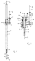
- in einer Seitenansicht eine teleskopierbare Bohrstange mit einem Drehantrieb;
- Fig. 2
- in einer Seitenansicht in vergrößerter Darstellung den Drehantrieb mit einer partiell und geschnitten dargestellten Bohrstange;
- Fig. 3
- in einer Seitenansicht ein Drebbohrgerät in Gesamtdarstellung; und
- Fig. 4
- in einer Seitenansicht ein Drehbohrgerät mit teleskopierter Bohrstange.
- Fig. 1
- in a side view a telescopic boring bar with a rotary drive;
- Fig. 2
- in a side view in an enlarged view, the rotary drive with a boring bar shown partially and in section;
- Fig. 3
- in a side view a rotary drilling machine in an overall view; and
- Fig. 4
- in a side view a rotary drilling rig with telescopic boring bar.
Eine teleskopierbare Bohr- oder Kellystange 1 mit an sich
bekanntem Aufbau enthält beispielhaft ein inneres Rohr 2,
das auch eine Stange sein kann (siehe Fig. 2), an dessen
Oberende ein Kellyauge 3 zum Befestigen eines Tragseils 4
und an dessen Unterende ein Bohrwerkzeug 5 angebracht ist.
Das innere Rohr 2 ist in einem mittleren Rohr 6 durch (nicht
dargestellte) Mitnehmerleisten axial verschiebbar geführt
und gleichzeitig drehfest gelagert und somit in bekannter
Weise teleskopierbar. Das mittlere Rohr 6 wiederum ist in
einem äußeren Rohr 7 in gleicher Weise aufgenommen. Das äußere
Rohr 7 ist in einem Durchgang eines Kraftdrehkopfes 8
eines Drehantriebs 9 axial verschiebbar aufgenommen und über
einen Mitnehmerring 10 des Kraftdrehkopfes 8 und zugeordnete
Mitnehmerleisten am Umfang des äußeren Rohres 7 rotatorisch
antreibbar. Der Kraftdrehkopf 8 ist mittels eines Getriebeschlittens
11 an einem Mast 12 (siehe Fig. 3) eines Drehbohrgerätes
13 verschiebbar gelagert und mittels eines Seiles
14 und einer Seilwinde 15 über die Länge des Mastes 12
auf- und abbewegbar. Der hast 12 ist an einem verfahrbaren
Geräteträger 16 gelagert, der eine Kabine 17 für eine Bedienperson
aufweist.A telescopic drill or Kelly
Die einzelnen Rohre 2, 6, 7 weisen obere und untere Endanschläge
auf, die ihren Verschiebe- oder Teleskopierweg bei
ihren relativen axialen Bewegungen begrenzen. Durch gegenseitiges
Verdrehen von jeweils zwei Rohren über den Drehantrieb
können Verriegelungen eingerastet werden, so daß die
Rohre untereinander und an dem Kraftdrehkopf 8 axial festgelegt
sind und eine axiale Bohrkraft auf das Bohrgestänge
(die Kellystange 1) aufgebracht werden kann. Durch entgegengesetzte
Drehung können die Verriegelungen in bekannter Weise
wieder gelöst werden.The
Mit dem Tragseil 4 und einer zugehörigen Seilwinde 18 kann
die Bohr- oder Kellystange 1 angehoben und abgesenkt werden.
Mit dem Vorschubseil 14 (alternativ mit einem hydraulischen
Vorschubzylinder) kann der Kraftdrehkopf 8 angehoben und mit
der Vorschubbewegung beim Bohren zusammen mit der Bohrstange
1 abgesenkt werden.With the
Dieser bisher beschriebene Aufbau und die Betriebsweise sind aus dem Stand der Technik bekannt.This structure and the mode of operation described so far are known from the prior art.
Zur Messung der Zug- oder Hebekraft F1 in dem Tragseil 4 sowie
der Zug- oder Hebekraft F2 in dem Vorschubseil 14, das
den Kraftdrehkopf 8 trägt, oder alternativ in einer entsprechenden
hydraulischen Zylindereinrichtung, sind jeweilige
Kraftmeßeinrichtungen oder Sensoren (nicht dargestellt) vorgesehen,
die ein jeweiliges Zugkraftsignal an eine Vergleichseinrichtung
liefern.For measuring the tensile or lifting force F 1 in the
In Fig. 4 ist ein Drehbohrgerät mit einem Hydraulikzylinder
als Halte- oder Vorschubeinrichtung für den Kraftdrehkopf 8
dargestellt. Die nachfolgenden Kräftebetrachtungen gelten
sowohl für Zylinder als auch für Winden als Vorschubeinrichtungen.4 is a rotary drilling machine with a hydraulic cylinder
as a holding or feed device for the
Bei der nachfolgenden schrittweisen Betrachtung werden zur
Vereinfachung lediglich das Gewicht der Rohre 2, 6 und 7 (d.
h. ohne Gewicht des Bohrwerkzeugs, des Kraftdrehkopfes oder
dergleichen) berücksichtigt.In the following step-by-step analysis, the
Simplification only the weight of
Vor dem Herausziehen oder Anheben der Bohrstange 1 stützt
sich das äußere Rohr 7 mit seinem topfartigen Absatz 20
(siehe Fig. 2) am Kraftdrehkopf 8 ab, so daß der Kraftdrehkopf
8 das Gewicht der gesamten Bohrstange 1 trägt. Fig. 2
zeigt ferner auf dem Kraftdrehkopf 8 angebrachte Dämpfungseinrichtung
mit Federn 21. An den Federn 21 können Meßeinrichtungen
zur Krafterfassung angebracht sein. Besonders
einfach kann durch kraftproportionale Wegmessung oder durch
Piezokraftaufnehmer oder dergleichen die Messung durchgeführt
werden.Before pulling out or lifting the
Gegenüber der Messung der Zug- oder Hebekraft F2 Vorhubseil
14 wird hier nicht das Gewicht des Kraftdrehkopfes 8 mitgemessen.Compared to the measurement of the pulling or lifting force F 2 pre-lifting rope 14, the weight of the
Es ergibt sich die folgende Kräftegleichung:
Dabei ist mit FR1, FR2 und FR3 jeweils die Gewichtskraft des
inneren, des mittleren und des äußeren Rohres 2 bzw. 6 bzw.
7 bezeichnet (siehe Fig. 4).F R1 , F R2 and F R3 denote the weight of the inner, middle and
Beim anfänglichen Anheben der Bohrstange 1 wird zuerst das
innere Rohr 2 über das Tragseil 4 angehoben:
Beim weiteren Anheben gelangt das innere Rohr 2 an einen
Längsanschlag am mittleren Rohr 6 und hebt dieses mit an:
Beim weiteren Anheben gelangt schließlich das innere Rohr 2
mit dem mittleren Rohr 6 an den Längsanschlag des äußeren
Rohres 7 und hebt dieses relativ zum Kraftdrehkopf 8 mit an:
In der Vergleichseinrichtung wird die Zugkraft F1 unter Berücksichtigung
des schon erfolgten Hubweges des Tragseils 4
mit den gespeicherten Gewichtskräften FR1, FR2 und FR3 verglichen,
wobei bei ordnungsgemäßem Betrieb während einem ersten
Hubweg, der der Länge des inneren Rohres 2 proportional ist,
sowie während der weiteren Hubwege die oben genannten Kräfteverhältnisse
auftreten werden. Weichen die gemessenen
Kraftwerte F1 von den zulässigen, berechneten Kraftwerten um
mehr als einen bestimmten Kraftwert voneinander ab, wie dies
bei einem gegenseitigen Verklemmen zweier Rohre auftreten
kann, wird von der Vergleichseinrichtung ein Signal erzeugt.
Dieses Signal wird beispielsweise in der Kabine 17 des Geräteträgers
16 als Warnsignal dargestellt, beispielsweise als
optische Anzeige oder als akustisches Warnsignal, so daß die
Bedienperson rechtzeitig eine Aktion einleiten kann. So kann
sie beispielsweise das Anheben stoppen und durch Absenken
die verklemmten Rohre wieder lösen. Das Signal kann aber
auch eine Steuerung betätigen, die von sich aus das weitere
Anheben der Bohrstange stoppt.In the comparison device, the tensile force F 1 is compared with the stored weight forces F R1 , F R2 and F R3 , taking into account the stroke path of the
Durch Wegmessung an dem Seil 14 kann die Position des Kraftdrehkopfes
8 am Mast 12 und damit die Ausgangsposition der
Bohrstange 1 beim Hochziehen bestimmt werden und eine Null-Einstellung
für das Tragseil 4 bei Beginn des Hochziehens
vorgenommen werden. Es kann daher bei jeder Höhenposition
des Drehantriebs 9 am Mast 12 dieses Verfahren dadurch vorgenommen
werden, daß die Positionsabweichung des Drehantriebs
von der Nullstellung bei der Seilwegmessung am Seil 4
berücksichtigt wird, d.h. je nach Richtung addiert oder subtrahiert
wird.The position of the power turret can be determined by measuring the distance on the
Die obigen Kräftegleichungen zeigen, daß mit unterschiedlichen
Meßmöglichkeiten und Meßanordnungen das erfindungsgemäße
Ziel erreicht werden kann. So kann entweder nur die
Kraft F1 im Tragseil 4 oder nur die für den Kraftdrehkopf 8
erforderliche Haltekraft F2 gemessen werden, die dann mit
den theoretisch vorhandenen Zugkräften verglichen werden,
die sich jeweils in Abhängigkeit vom zurückgelegten Hubweg
und der damit einhergehenden theoretischen Gewichtskraftveränderung
aufgrund der in unterschiedlicher Anzahl zu haltenden
Rohre verändern. Jedoch können auch die Kräfte F1 und
F2 verglichen werden, um ein Signal zu erhalten, das über
den sicheren Betrieb beim Hochziehen einer teleskopierbaren
Bohrstange Auskunft gibt.The above equations of forces show that the aim according to the invention can be achieved with different measuring possibilities and measuring arrangements. For example, either only the force F 1 in the
Claims (12)
dadurch gekennzeichnet,
characterized by
dadurch gekennzeichnet,
characterized by
dadurch gekennzeichnet,
characterized by
dadurch gekennzeichnet,
characterized by
dadurch gekennzeichnet,
characterized by
dadurch gekennzeichnet,
characterized by
dadurch gekennzeichnet,
characterized by
dadurch gekennzeichnet,
characterized by
dadurch gekennzeichnet,
characterized by
dadurch gekennzeichnet,
characterized by
dadurch gekennzeichnet,
characterized by
dadurch gekennzeichnet,
characterized by
Applications Claiming Priority (2)
| Application Number | Priority Date | Filing Date | Title |
|---|---|---|---|
| DE19813902 | 1998-03-28 | ||
| DE19813902A DE19813902C1 (en) | 1998-03-28 | 1998-03-28 | Method of monitoring a telescopic bore rod |
Publications (3)
| Publication Number | Publication Date |
|---|---|
| EP0947664A2 true EP0947664A2 (en) | 1999-10-06 |
| EP0947664A3 EP0947664A3 (en) | 2000-12-06 |
| EP0947664B1 EP0947664B1 (en) | 2004-08-25 |
Family
ID=7862770
Family Applications (1)
| Application Number | Title | Priority Date | Filing Date |
|---|---|---|---|
| EP99104296A Expired - Lifetime EP0947664B1 (en) | 1998-03-28 | 1999-03-03 | Method for monitoring a telescopic drill string and a protection device for a telescopic drill string |
Country Status (3)
| Country | Link |
|---|---|
| EP (1) | EP0947664B1 (en) |
| AT (1) | ATE274634T1 (en) |
| DE (2) | DE19813902C1 (en) |
Cited By (7)
| Publication number | Priority date | Publication date | Assignee | Title |
|---|---|---|---|---|
| EP1580398A1 (en) | 2004-03-23 | 2005-09-28 | BAUER Maschinen GmbH | Apparatus and method for subsoil construction |
| ITTO20100436A1 (en) * | 2010-05-25 | 2011-11-26 | Soilmec Spa | TELESCOPIC AUCTION (KELLY) FOR THE IMPLEMENTATION OF PILLAR POLES. |
| EP3287588A1 (en) * | 2016-08-24 | 2018-02-28 | BAUER Maschinen GmbH | Machine tool and method for machining a soil |
| CN109138971A (en) * | 2018-09-28 | 2019-01-04 | 徐州徐工基础工程机械有限公司 | Drilling rod operation indicating method and system |
| CN112780175A (en) * | 2020-12-28 | 2021-05-11 | 湖北首开机械有限公司 | Safe drilling device |
| EP3882398A1 (en) * | 2020-03-17 | 2021-09-22 | BAUER Maschinen GmbH | Boring bar and method for retrofitting a cage rod assembly |
| EP3907371A1 (en) * | 2020-05-07 | 2021-11-10 | BAUER Maschinen GmbH | Machine tool and method for processing a soil |
Families Citing this family (7)
| Publication number | Priority date | Publication date | Assignee | Title |
|---|---|---|---|---|
| DE10116342C2 (en) * | 2001-04-02 | 2003-02-27 | Bauer Maschinen Gmbh | winch |
| DE10243744B4 (en) * | 2002-09-20 | 2006-10-12 | Bauer Maschinen Gmbh | Displacement device and construction machine with displacement device |
| DE102012019850A1 (en) | 2012-10-10 | 2014-04-10 | Liebherr-Werk Nenzing Gmbh | Method for monitoring drill pipes, involves driving outer bar by rotary drive before rotational position of outer bar is checked, during axial displacement of drill pipe is occurred by performing rotating movement in opposite direction |
| DE102014109918A1 (en) | 2014-07-15 | 2016-01-21 | Bauer Maschinen Gmbh | Construction machine and method for controlling a construction machine |
| CA3049693A1 (en) | 2017-01-18 | 2018-07-26 | Minex Crc Ltd | Mobile coiled tubing drilling apparatus |
| DE102017002674A1 (en) * | 2017-03-20 | 2018-09-20 | Liebherr-Werk Nenzing Gmbh | Working machine for carrying out drilling work |
| DE102017002675A1 (en) * | 2017-03-20 | 2018-09-20 | Liebherr-Werk Nenzing Gmbh | Method for determining the geometry of a telescopic Kelly bar |
Family Cites Families (2)
| Publication number | Priority date | Publication date | Assignee | Title |
|---|---|---|---|---|
| US5630477A (en) * | 1995-06-02 | 1997-05-20 | Minatre William H | Downcrowdable telescopic augering apparatus |
| DE19626223C2 (en) * | 1996-06-29 | 2000-08-10 | Klemm Bohrtech | Kelly bar drill |
-
1998
- 1998-03-28 DE DE19813902A patent/DE19813902C1/en not_active Expired - Fee Related
-
1999
- 1999-03-03 DE DE59910317T patent/DE59910317D1/en not_active Expired - Lifetime
- 1999-03-03 AT AT99104296T patent/ATE274634T1/en not_active IP Right Cessation
- 1999-03-03 EP EP99104296A patent/EP0947664B1/en not_active Expired - Lifetime
Non-Patent Citations (1)
| Title |
|---|
| None |
Cited By (17)
| Publication number | Priority date | Publication date | Assignee | Title |
|---|---|---|---|---|
| EP1580398A1 (en) | 2004-03-23 | 2005-09-28 | BAUER Maschinen GmbH | Apparatus and method for subsoil construction |
| ITTO20100436A1 (en) * | 2010-05-25 | 2011-11-26 | Soilmec Spa | TELESCOPIC AUCTION (KELLY) FOR THE IMPLEMENTATION OF PILLAR POLES. |
| EP2390458A1 (en) | 2010-05-25 | 2011-11-30 | Soilmec S.p.A. | Drilling device with telescoping Kelly tube |
| CN109563731B (en) * | 2016-08-24 | 2021-04-13 | 包尔机械有限公司 | Work machine and method for treating ground |
| US11473375B2 (en) | 2016-08-24 | 2022-10-18 | Bauer Maschinen Gmbh | Working machine and method for working the ground |
| CN109563731A (en) * | 2016-08-24 | 2019-04-02 | 包尔机械有限公司 | Work mechanism and method for handling ground |
| RU2722612C1 (en) * | 2016-08-24 | 2020-06-02 | Бауэр Машинен Гмбх | Working machine and method of soil treatment |
| EP3287588A1 (en) * | 2016-08-24 | 2018-02-28 | BAUER Maschinen GmbH | Machine tool and method for machining a soil |
| WO2018036713A1 (en) * | 2016-08-24 | 2018-03-01 | Bauer Maschinen Gmbh | Working machine and method for working a soil |
| CN109138971A (en) * | 2018-09-28 | 2019-01-04 | 徐州徐工基础工程机械有限公司 | Drilling rod operation indicating method and system |
| CN109138971B (en) * | 2018-09-28 | 2023-12-05 | 徐州徐工基础工程机械有限公司 | Drill rod operation prompting method and system |
| EP3882398A1 (en) * | 2020-03-17 | 2021-09-22 | BAUER Maschinen GmbH | Boring bar and method for retrofitting a cage rod assembly |
| WO2021185499A1 (en) * | 2020-03-17 | 2021-09-23 | Bauer Maschinen Gmbh | Drilling rod and method for retrofitting a kelly bar arrangement |
| US11927059B2 (en) | 2020-03-17 | 2024-03-12 | Bauer Maschinen Gmbh | Drill rod and method for retrofitting a Kelly bar arrangement |
| EP3907371A1 (en) * | 2020-05-07 | 2021-11-10 | BAUER Maschinen GmbH | Machine tool and method for processing a soil |
| WO2021224168A1 (en) * | 2020-05-07 | 2021-11-11 | Bauer Maschinen Gmbh | Work machine and method for working the ground |
| CN112780175A (en) * | 2020-12-28 | 2021-05-11 | 湖北首开机械有限公司 | Safe drilling device |
Also Published As
| Publication number | Publication date |
|---|---|
| DE19813902C1 (en) | 1999-06-17 |
| DE59910317D1 (en) | 2004-09-30 |
| ATE274634T1 (en) | 2004-09-15 |
| EP0947664B1 (en) | 2004-08-25 |
| EP0947664A3 (en) | 2000-12-06 |
Similar Documents
| Publication | Publication Date | Title |
|---|---|---|
| EP0947664B1 (en) | Method for monitoring a telescopic drill string and a protection device for a telescopic drill string | |
| DE2615086C2 (en) | Device for handling casing pipes | |
| DE102010020016B4 (en) | Crane and method of erecting the crane | |
| EP0235585A1 (en) | Silo-unloading arrangement with telescope chute in the silo | |
| DE3642387C2 (en) | ||
| DE102015115146A1 (en) | Construction machine and method for moving up and down a lifting element | |
| DE102012019850A1 (en) | Method for monitoring drill pipes, involves driving outer bar by rotary drive before rotational position of outer bar is checked, during axial displacement of drill pipe is occurred by performing rotating movement in opposite direction | |
| DE102019130562A1 (en) | Telescopic lifting unit | |
| DE19512070C2 (en) | Drill | |
| DE202018105169U1 (en) | Movable passenger lift | |
| DE2001060C3 (en) | Position indicator for the storage head of a storage device for pipe pulls arranged in a derrick | |
| DE3018560C2 (en) | ||
| DE102011052183A1 (en) | hoist | |
| DE2542012C3 (en) | Device for driving a driven pile | |
| DE19512109C2 (en) | Drill | |
| DE10113561B4 (en) | Feed device for a piling and / or drilling device | |
| DE102005029595B4 (en) | Drilling rig with a mast and a telescopic bracket for a drill pipe | |
| DE19626223C2 (en) | Kelly bar drill | |
| DE2212876A1 (en) | Telescopic rod for machine for foundation work | |
| DE2433015C3 (en) | Lifting device with a vertically fixable mast | |
| DE2328740A1 (en) | OVERLOAD PROTECTION DEVICE FOR A LIFT | |
| DE1483799A1 (en) | Extendable mast | |
| DE112014004373T5 (en) | Apparatus for controlling a brake of a drum of a lift of a drilling rig and method of controlling such a device | |
| DE2732117A1 (en) | METHOD AND DEVICE FOR NOISE-FREE AND VIBRATION-FREE PLACING OF A PILOT | |
| DE2737449A1 (en) | Telescopic arm for reactor pressure vessel inspection - has rigid curved section steel tape as push and pull drive with frequent supports to prevent buckling |
Legal Events
| Date | Code | Title | Description |
|---|---|---|---|
| PUAI | Public reference made under article 153(3) epc to a published international application that has entered the european phase |
Free format text: ORIGINAL CODE: 0009012 |
|
| AK | Designated contracting states |
Kind code of ref document: A2 Designated state(s): AT DE FR IT |
|
| AX | Request for extension of the european patent |
Free format text: AL;LT;LV;MK;RO;SI |
|
| PUAL | Search report despatched |
Free format text: ORIGINAL CODE: 0009013 |
|
| RIC1 | Information provided on ipc code assigned before grant |
Free format text: 7E 21B 17/07 A, 7E 21B 19/08 B |
|
| AK | Designated contracting states |
Kind code of ref document: A3 Designated state(s): AT BE CH CY DE DK ES FI FR GB GR IE IT LI LU MC NL PT SE |
|
| AX | Request for extension of the european patent |
Free format text: AL;LT;LV;MK;RO;SI |
|
| 17P | Request for examination filed |
Effective date: 20001201 |
|
| AKX | Designation fees paid |
Free format text: AT DE FR IT |
|
| RAP1 | Party data changed (applicant data changed or rights of an application transferred) |
Owner name: BAUER MASCHINEN GMBH |
|
| 17Q | First examination report despatched |
Effective date: 20031118 |
|
| GRAP | Despatch of communication of intention to grant a patent |
Free format text: ORIGINAL CODE: EPIDOSNIGR1 |
|
| GRAS | Grant fee paid |
Free format text: ORIGINAL CODE: EPIDOSNIGR3 |
|
| GRAA | (expected) grant |
Free format text: ORIGINAL CODE: 0009210 |
|
| AK | Designated contracting states |
Kind code of ref document: B1 Designated state(s): AT DE FR IT |
|
| REF | Corresponds to: |
Ref document number: 59910317 Country of ref document: DE Date of ref document: 20040930 Kind code of ref document: P |
|
| ET | Fr: translation filed | ||
| PLBE | No opposition filed within time limit |
Free format text: ORIGINAL CODE: 0009261 |
|
| STAA | Information on the status of an ep patent application or granted ep patent |
Free format text: STATUS: NO OPPOSITION FILED WITHIN TIME LIMIT |
|
| 26N | No opposition filed |
Effective date: 20050526 |
|
| PGFP | Annual fee paid to national office [announced via postgrant information from national office to epo] |
Ref country code: AT Payment date: 20070323 Year of fee payment: 9 |
|
| PG25 | Lapsed in a contracting state [announced via postgrant information from national office to epo] |
Ref country code: AT Free format text: LAPSE BECAUSE OF NON-PAYMENT OF DUE FEES Effective date: 20080303 |
|
| REG | Reference to a national code |
Ref country code: FR Ref legal event code: PLFP Year of fee payment: 18 |
|
| REG | Reference to a national code |
Ref country code: FR Ref legal event code: PLFP Year of fee payment: 19 |
|
| REG | Reference to a national code |
Ref country code: FR Ref legal event code: PLFP Year of fee payment: 20 |
|
| PGFP | Annual fee paid to national office [announced via postgrant information from national office to epo] |
Ref country code: IT Payment date: 20180322 Year of fee payment: 20 Ref country code: FR Payment date: 20180326 Year of fee payment: 20 |
|
| PGFP | Annual fee paid to national office [announced via postgrant information from national office to epo] |
Ref country code: DE Payment date: 20180328 Year of fee payment: 20 |
|
| REG | Reference to a national code |
Ref country code: DE Ref legal event code: R071 Ref document number: 59910317 Country of ref document: DE |