EP0946901B1 - Dispositif d'impression electrographique comportant deux points de duplication - Google Patents
Dispositif d'impression electrographique comportant deux points de duplication Download PDFInfo
- Publication number
- EP0946901B1 EP0946901B1 EP97952745A EP97952745A EP0946901B1 EP 0946901 B1 EP0946901 B1 EP 0946901B1 EP 97952745 A EP97952745 A EP 97952745A EP 97952745 A EP97952745 A EP 97952745A EP 0946901 B1 EP0946901 B1 EP 0946901B1
- Authority
- EP
- European Patent Office
- Prior art keywords
- printing
- toner image
- printing device
- toner
- paper web
- Prior art date
- Legal status (The legal status is an assumption and is not a legal conclusion. Google has not performed a legal analysis and makes no representation as to the accuracy of the status listed.)
- Expired - Lifetime
Links
Images


Classifications
-
- G—PHYSICS
- G03—PHOTOGRAPHY; CINEMATOGRAPHY; ANALOGOUS TECHNIQUES USING WAVES OTHER THAN OPTICAL WAVES; ELECTROGRAPHY; HOLOGRAPHY
- G03G—ELECTROGRAPHY; ELECTROPHOTOGRAPHY; MAGNETOGRAPHY
- G03G15/00—Apparatus for electrographic processes using a charge pattern
- G03G15/22—Apparatus for electrographic processes using a charge pattern involving the combination of more than one step according to groups G03G13/02 - G03G13/20
- G03G15/32—Apparatus for electrographic processes using a charge pattern involving the combination of more than one step according to groups G03G13/02 - G03G13/20 in which the charge pattern is formed dotwise, e.g. by a thermal head
-
- G—PHYSICS
- G03—PHOTOGRAPHY; CINEMATOGRAPHY; ANALOGOUS TECHNIQUES USING WAVES OTHER THAN OPTICAL WAVES; ELECTROGRAPHY; HOLOGRAPHY
- G03G—ELECTROGRAPHY; ELECTROPHOTOGRAPHY; MAGNETOGRAPHY
- G03G15/00—Apparatus for electrographic processes using a charge pattern
- G03G15/01—Apparatus for electrographic processes using a charge pattern for producing multicoloured copies
- G03G15/0142—Structure of complete machines
- G03G15/0147—Structure of complete machines using a single reusable electrographic recording member
- G03G15/0152—Structure of complete machines using a single reusable electrographic recording member onto which the monocolour toner images are superposed before common transfer from the recording member
- G03G15/0163—Structure of complete machines using a single reusable electrographic recording member onto which the monocolour toner images are superposed before common transfer from the recording member primary transfer to the final recording medium
-
- G—PHYSICS
- G03—PHOTOGRAPHY; CINEMATOGRAPHY; ANALOGOUS TECHNIQUES USING WAVES OTHER THAN OPTICAL WAVES; ELECTROGRAPHY; HOLOGRAPHY
- G03G—ELECTROGRAPHY; ELECTROPHOTOGRAPHY; MAGNETOGRAPHY
- G03G15/00—Apparatus for electrographic processes using a charge pattern
- G03G15/22—Apparatus for electrographic processes using a charge pattern involving the combination of more than one step according to groups G03G13/02 - G03G13/20
- G03G15/23—Apparatus for electrographic processes using a charge pattern involving the combination of more than one step according to groups G03G13/02 - G03G13/20 specially adapted for copying both sides of an original or for copying on both sides of a recording or image-receiving material
- G03G15/231—Arrangements for copying on both sides of a recording or image-receiving material
-
- G—PHYSICS
- G03—PHOTOGRAPHY; CINEMATOGRAPHY; ANALOGOUS TECHNIQUES USING WAVES OTHER THAN OPTICAL WAVES; ELECTROGRAPHY; HOLOGRAPHY
- G03G—ELECTROGRAPHY; ELECTROPHOTOGRAPHY; MAGNETOGRAPHY
- G03G15/00—Apparatus for electrographic processes using a charge pattern
- G03G15/01—Apparatus for electrographic processes using a charge pattern for producing multicoloured copies
- G03G15/0142—Structure of complete machines
- G03G15/0178—Structure of complete machines using more than one reusable electrographic recording member, e.g. one for every monocolour image
- G03G15/0184—Structure of complete machines using more than one reusable electrographic recording member, e.g. one for every monocolour image at least one recording member having plural associated developing units
-
- G—PHYSICS
- G03—PHOTOGRAPHY; CINEMATOGRAPHY; ANALOGOUS TECHNIQUES USING WAVES OTHER THAN OPTICAL WAVES; ELECTROGRAPHY; HOLOGRAPHY
- G03G—ELECTROGRAPHY; ELECTROPHOTOGRAPHY; MAGNETOGRAPHY
- G03G2215/00—Apparatus for electrophotographic processes
- G03G2215/00362—Apparatus for electrophotographic processes relating to the copy medium handling
- G03G2215/00443—Copy medium
- G03G2215/00451—Paper
- G03G2215/00455—Continuous web, i.e. roll
- G03G2215/00459—Fan fold, e.g. CFF, normally perforated
-
- G—PHYSICS
- G03—PHOTOGRAPHY; CINEMATOGRAPHY; ANALOGOUS TECHNIQUES USING WAVES OTHER THAN OPTICAL WAVES; ELECTROGRAPHY; HOLOGRAPHY
- G03G—ELECTROGRAPHY; ELECTROPHOTOGRAPHY; MAGNETOGRAPHY
- G03G2215/00—Apparatus for electrophotographic processes
- G03G2215/01—Apparatus for electrophotographic processes for producing multicoloured copies
- G03G2215/0103—Plural electrographic recording members
- G03G2215/0106—At least one recording member having plural associated developing units
-
- G—PHYSICS
- G03—PHOTOGRAPHY; CINEMATOGRAPHY; ANALOGOUS TECHNIQUES USING WAVES OTHER THAN OPTICAL WAVES; ELECTROGRAPHY; HOLOGRAPHY
- G03G—ELECTROGRAPHY; ELECTROPHOTOGRAPHY; MAGNETOGRAPHY
- G03G2215/00—Apparatus for electrophotographic processes
- G03G2215/01—Apparatus for electrophotographic processes for producing multicoloured copies
- G03G2215/0103—Plural electrographic recording members
- G03G2215/0119—Linear arrangement adjacent plural transfer points
Definitions
- the invention relates to an electrographic printing device with at least one printing unit that has a toner image carrier contains, on the endless peripheral surface of toner according to a pictorial distribution can be applied.
- Such an electrographic printing device is in one Printer or copier used.
- On the toner image carrier is carried out using an electrographic process, e.g. by Exposing a photoconductor or by magnetizing one magnetically sensitive layer, a latent image applied. According to the pictorial distribution of the electrical charges or the magnetic pole is attached to the latent image Toner.
- On a carrier material generally paper then transfer the toner at the transfer location. The toner image will be fixed on the carrier material later.
- EP 0629931 A1 (applicant XEIKON) is an electrostatic Printer known in which a carrier web in vertical Direction passed between a plurality of toner image carriers becomes.
- Each toner image carrier has a toner image generating device.
- the toner is at one transfer location the toner image carrier is transferred to the carrier web.
- By arranging toner image carriers on both sides lengthways the vertically running carrier web is a duplex print with different toner colors possible.
- the well-known device has a complex structure, a complicated substrate management and is voluminous.
- EP 0 433 444 31 (applicant: Eastman Kodak Company) a printer is known in which along a photoconductor belt several developer stations arranged as a toner image carrier are. Every development station can do this from an exposure station generated charge image with toner of a predetermined Color. The toner image created on the photoconductor belt is then at a single transfer point on the Transfer carrier material.
- This printer is also technical complex and can only in the different operating modes realize low printing speeds.
- JP-A-07225504 a printing device is known which is equipped with several printing units, which on Print single sheets of images. With one Printing device have the respective photoconductor interfaces, which result from the single sheet transport and on which do not produce a latent image. Printing on web-shaped carrier material is at the known printing device not possible.
- a single toner image carrier is used in the invention for example in the form of a photoconductor drum or one Photoconductor belt.
- the photoconductor tape is in this case to be preferred, since it is suitable due to its structure, a Variety of aggregates along an elongated photosensitive Arrange area.
- the toner image carrier is the outer peripheral surface of the photoconductor belt fully rechargeable with a latent charge pattern.
- a continuous endless photoconductor belt is known per se for single sheet printers.
- Such a photoconductor band has an interface at which no charge pattern can be generated. This interface is usually through marked an index hole and when exposed by the Exposure unit taken into account by the device control.
- the interface is then ensured that that the seam is becoming more and more consecutive between two ends Single sheets are located so that the seam not noticeable in the printed image.
- tape material as the carrier material is now according to the Invention the interface as small as possible or it is not Interface available. So the photoconductor tape is perfect to coat with photoactive material so that it lengthways its circumferential surface completely with a latent charge pattern is rechargeable. In this way, the tape material be printed without interruption - there is none Pressure gap.
- This multi-color printing can in the simple case a spot color print or with appropriate process control full-color printing with the process colors yellow, magenta, Be cyan and black.
- a repetitive can be used to apply different toner images
- Operation can be provided in which the carrier material the transfer points repeated by a forward movement and a backward movement is made. With every passing in the forward direction, a toner image is placed on the carrier material transfer. In this way, toner images can be different Color from the various development stations a peripheral portion on the photoconductor belt generated, collected on the substrate and then fixed together. With every backward movement is to swing the carrier material away from the conductor strip in order to the applied toner image or the applied toner images not to blur.
- Fig. 1 is a printing unit according to the invention schematically shown. It contains a photoconductor band 10, which under Rotary movement past two transfer printing points 12, 14 is used to apply toner to a carrier material, e.g. continuous To transfer paper webs 16.
- the photoconductor belt 10 is on the upper transfer point 12 sliding around a deflection unit 18 led around.
- a roller 20 arranged for deflecting the photoconductor belt 10.
- the length the photoconductor belt 10 is chosen so that enough space remains for the aggregates explained below.
- the plane running through the transfer printing points 12, 14 is slightly inclined towards the vertical, e.g. at an angle of 15 °, which makes the arrangement of the aggregates in a compact manner becomes possible.
- the paper webs 16 are horizontal in the printer led, which has advantages in terms of handling result in the event of an error.
- the photoconductor belt 10 is guided on several rollers 15. The direction of movement is indicated by the arrows P1, P2.
- a clamping element 17 can be switched in two positions. In the one position, the photoconductor belt 10 is stretched. In the the other position shown in dashed lines is the mechanical one Tension of the photoconductor belt 10 is reduced. In this Position, the photoconductor belt can be replaced or it can Maintenance work.
- the transfer printing points 12, 14 divide the photoconductor belt 10 into a first peripheral portion 22 and a second peripheral portion 24.
- the first peripheral portion 22 has one First image forming means 26; the second peripheral section 24 has a second one which forms a toner image Device 28.
- the first device 26 has one as a character generator 30 trained exposure unit, the light contains emitting diodes and also as an LED exposure unit referred to as.
- the character generator 30 generates on the Photoconductor tape 10 a latent charge image with a charge distribution according to the characters or picture elements to be printed. Are seen in the direction of rotation of the photoconductor belt 10 after the character generator 30 four developer stations 32, 34, 36, 38 arranged, the charge image with different colors Color the toner as described in more detail below becomes.
- a Charging corotron 40 Seen in the direction of rotation in front of the character generator 30 is a Charging corotron 40 arranged, which on the photoconductor belt 10th applies a basic charge.
- a Cleaning station 42 with upstream cleaning corotron 44 arranged in front of the charging corotron 40.
- the cleaning corotron 44 and the cleaning station 42 have the task after printing at the transfer location 14 still existing toner from the photoconductor belt 10 to remove this photoconductor tape for the following Exposure and toner absorption in a defined initial state bring to.
- the second device 28 has in the direction of rotation of the photoconductor belt 10 seen the same construction as the first device 26.
- the corresponding aggregates are therefore with the addition a marked and otherwise have the same reference numbers.
- duplex printing mode only one paper web 16 fed. First, e.g. at the lower transfer location 14 printed on one side of the paper web 16. Then the paper web 16 is turned and at the upper transfer location 12 printed the other side of the same paper web 16. Depending on Activation of the different developer stations 32 to 38 or 32a to 38a can between different toner colors to get voted.
- the operating mode Simplex two-color printing is the only one Paper web 16 provided with two printed images on the same page.
- the paper web 16 is fed to the transfer printing point 14. Then the printed page is printed without turning the transfer location 12 supplied. Since once printing using the a toner image forming second unit 28 and another done with the first unit 26, can according to the used developer stations 32a to 36a and 32 to 36 different colors can be printed.
- the still unprinted paper web 16 pivoted and pivoted, especially for the start and stop mode.
- the Side of the paper web 16 already an unfixed print image on. In this case, it is recommended to use the photoconductor 10 swing in and out.
- the paper web 16 In a repeating company, i.e. with forward movement and Backward movement of the paper web 16 at the transfer printing points 12, 14 can, depending on the number of developer stations used 32 to 38 or 32a to 38a several toner images one above the other be collected on the paper web 16.
- the printing speed goes in this mode according to the forward and backward movement back.
- the fixation is preferably carried out all color separations together in a single fuser.
- the paper web 16 is for collecting the toner images to pivot away from the photoconductor belt 10 with each backward movement, to blur the unfixed toner images avoid.
- Figure 2 shows schematically a printing unit with a photoconductor belt 10, through the two transfer printing points 12, 14 in two Circumferential sections 22, 24 is divided.
- the figure 1 Matching parts are labeled the same.
- the one on the first peripheral portion 22 forming a first toner image
- the device 26 contains 44, which generate a first toner image, a second character generator 50, a second developer station 52 and a upstream second charging corotron 54.
- the units 50, 52, 54 is either based on the well-known tri-level process or using a process developed by Océ Printing System on the first peripheral portion 22 of the photoconductor tape 10 a first latent charge image and then through the Developer station 32 generates a first toner image.
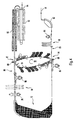
- FIG. 3 shows schematically the use of the printing unit according to the Invention in a printer, wherein a single paper web 16 is transported without intervention in an edge perforation.
- the Printing unit 60 has a structure as shown in FIG. 1 is.
- the only continuous paper web 16 is over a Quuntersrichtvorrichtug 62 fed which the paper web 16 in Roughly aligns the direction transverse to the transport direction.
- the paper is guided past a vacuum brake 64, which sucks the paper with negative pressure to the Longitudinal tension in the paper web 16 to a defined value to be able to hold.
- the paper web 16 then passes through a side guiding device 66, which is an exact side guide the paper web 16 for the subsequent transfer printing on Printing unit 60 controls.
- the transverse alignment device 62 is used for rough alignment and the side guide device 66 for fine lateral Alignment of the paper web 16.
- Toner becomes on the transfer printing corotron 68 transferred from the photoconductor belt 10 to the paper web 16 and fixed electrostatically.
- this fixation is still not smudge-proof.
- Dashed lines show that the paper web 16 can be pivoted away from the printing unit 60.
- the Paper web 16 passes through an intermediate fixing station after the transfer printing 70, which in this case works as an infrared heater. In this intermediate fixing station 70, the toner becomes so fixed that he no longer blurs when turning becomes.
- the dwell time in the heating zone of the intermediate fuser 70 is e.g. one second.
- the fixation is approx.
- the toner has a deflection unit 72 in which the paper web 16 is performed taut within a frame turner.
- This deflection unit is constructed so that it is either the Paper web 16 deflected without turning or with turning.
- transverse alignment device 74 aligned and moved past a vacuum brake 76 to then the other Side guide device 78 to be fed a fine adjustment of the lateral guidance of the paper web 16 performs.
- the paper web 16 can also be sent to the printing unit 60 at the upper transfer printing point swung up or swung away from this.
- the paper web 16 After this the paper web 16 has been printed twice, it will be the Fixing station 32 supplied, which carries out the final fixation. In this fuser, which is also used as infrared radiation heating is formed, the paper web 16 stays for approx. one second at a speed of 1.5 m / s. Both Toner images are now fixed on the paper web 16, and the paper web 16 is output via the take-off rollers 84.
- Simple simplex printing mode The only paper web 16 is printed only at a transfer printing point of the printing unit 60.
- Duplex printing mode The paper web 16 is on the first Transfer location printed on transfer printing corotron 68, then in the deflection unit 72 turned. Then the paper web 16 at the upper transfer location (transfer corotron 80) printed on the other side.
- Simplex multicolor printing mode on the transfer corotron 68 a toner image with a first color is applied.
- the Paper web 16 passes through the deflection unit 72 without turning.
- the same side is on the transfer corotron 80 with a toner image printed in a second color at full print speed.
- the paper web 16 is after printing on the transfer corotron 68 on the deflection unit 72 turned.
- the multi-color print on the front and back the paper web is done by repeating, i.e. by repeatedly moving the paper web back and forth. For each color, the paper web 16 must be moved forward once. Depending on the number of developer stations and the toner colors the printing speed decreases.
- Duplex full-color printing mode In this mode repetitive toner images with the process colors yellow, Magenta, cyan and black applied with appropriate process control, where highest fitting accuracy is required.
- Operating mode double simplex printing In this operating mode The deflection unit 72 is omitted. The transfer printing points on the transfer printing corotron 68, 80 a paper web 16 is fed to each. Appropriate process control makes both paper webs 16 printed independently of each other.
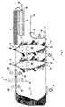
- Figure 4 shows schematically an arrangement with a printing unit according to the invention, the paper transport without intervention in an edge perforation of the paper web 16.
- the Elements, which correspond to those according to FIG. 3 are identified identically and will not be explained again.
- a special feature here is the deflection unit 72, which acts as a loop turner is formed, in which the provided with a toner image Side does not come into contact with any other part. Accordingly, must on the transfer corotron 68 on the paper web 16th applied toner image can not be temporarily fixed. Before the Transfer printing corotron 68 and transfer printing corotron 80 are respectively Free zones 83, 90 are provided for the repetitive printing operation with multiple toner images. The mechanical tension in the paper web 16 must be passed through the deflection unit 72 are dismantled.
- the fixing station 82 is a cooling device 92 downstream, through which the paper web 16 after passing through the fixing station 82 acting on both sides cooled again becomes.
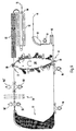
- Figure 5 shows schematically an arrangement with a printing unit 60 according to FIG. 1.
- the paper is transported by engaging the edge perforation of the paper web 16.
- Tractor drives 94 are used for paper transport, by means of transport spikes in marginal holes in the paper web 16 intervention.
- the edge-precise guidance of the Paper web 16 secured and components such as cross aligning device, Lateral guiding device, vacuum brake, suction table can be omitted.
- the components that follow those Figure 3 and Figure 4 match, are identified identically. Their respective function therefore does not have to be explained again become.
- the transfer locations 14, 12 near the transfer corotrons 68, 80 the paper web 16 is pivoted, as by pulled out and dashed lines can be recognized.
- the arrangement according to FIG. 5 can have the same operating modes as 3 can be realized.
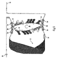
- Figure 6 schematically shows an arrangement in many parts corresponds to Figure 4.
- the printing unit is constructed as shown in Figure 2, i.e. on their respective circumferential section overlaid by the photoconductor belt 10 two toner images, so that at high print speeds a duplex multicolor print is possible.
- the paper is transported without any intervention into an edge perforation in the paper web 16, so that suction tables 96, 98, 102 are required.
- the deflection unit 72 is as Loop deflection unit formed, i.e. the paper web 16 becomes flaccid without touching the fixed toner image deflected on one side of the paper web 16. When redirecting the paper web 16 can be turned or not.
- the suction tables are on the Arrange page without printed image, as shown by dashed lines the suction tables 98 'and 102' is shown. Because when printing at a transfer location with the transfer printing corotron 68 or the Transfer printing corotron 80 already has a two-tone toner image one side of the paper web is applied, which are related possible with the operating modes mentioned in FIG. 3, however with the expansion of two-tone toner images each Printing. If the deflection unit 72 is omitted and two independent paper webs 16 at the transfer printing points 14, 12 are transferred to the transfer printing corotrons 68 and 80, respectively Simplex two-color printing possible at full printing speed.
- Figure 7 shows schematically an arrangement in which two printing units 100 are arranged in series according to FIG each transfer point 14, 14, 12, 12 a toner image with at least two toner colors applied to one side of the paper web 16 can be.
- the suction table 86 is designed to be lowerable at both transfer printing points 14, 14 of the two printing units 100, 100 simultaneously the paper web 16 lower.
- the arrangement according to FIG. 7 makes it possible to a four-color print on each side of the paper web 16 applied. With suitable process control it is in duplex mode full color printing at high speed possible. If the deflection unit 72 is omitted, so two paper webs 16 can be printed independently of one another be, depending on the equipment of the printing units 100, 100 that Printing on one side of the respective paper web 16 with up to four colors is possible.
Landscapes
- Physics & Mathematics (AREA)
- General Physics & Mathematics (AREA)
- Color Electrophotography (AREA)
- Electrostatic Charge, Transfer And Separation In Electrography (AREA)
Claims (18)
- Appareil d'impression électrographique comprenant au moins un dispositif d'impression qui comporte un support (10) d'image formée par du toner sur la surface périphérique sans fin duquel du toner peut être déposé avec une répartition qui est fonction de la forme de l'image,dans lequel, au niveau du support (10) d'image de toner, un matériau de support (16) en forme de bande, comportant ou non des perforations marginales, passe par deux emplacements de duplication (12, 14) qui sont distants l'un de l'autre sur la surface périphérique, et qui partagent cette surface périphérique en une première section périphérique (22) et une seconde section périphérique (24),dans lequel au niveau des emplacements de duplication (12, 14) le toner se trouvant sur le support (10) d'image formée par du toner peut être transféré sur le matériau de support (16),dans lequel un premier dispositif (26) de génération d'une image formée par du toner est agencé le long de la première section périphérique (22), et un second dispositif (28) de génération d'image formée par du toner est agencé le long de la seconde section périphérique (24),dans lequel il est prévu une bande photoconductrice (10) pour servir de support d'image formée par du toner,et dans lequel la surface périphérique extérieure de la bande photoconductrice (10) peut être totalement chargée avec une image latente.
- Appareil d'impression selon la revendication 1, caractérisé en ce que les premier et second dispositifs (26, 28) de génération d'image formée par du toner comportent chacun au moins une unité (30, 30a ; 50, 50a) de génération d'image pour générer une image latente sur le support (10) d'image formée par du toner, et au moins une station de développement (32, 34, 36, 38 ; 32a, 34a, 36a, 38a ; 52, 52a) qui colore l'image latente avec du toner.
- Appareil d'impression selon la revendication 2, caractérisé en ce que l'unité de génération d'image comporte une unité d'éclairement, de préférence une unité d'éclairement à laser ou bien une unité d'éclairement à LED (30, 30a ; 50, 50a).
- Dispositif selon la revendication 3, caractérisé en ce que les premier et second dispositifs (26, 28) de génération d'image formée par du toner comportent chacun une station de nettoyage (40, 40a ; 54, 54a) agencée en amont de l'unité d'éclairement, par référence au sens de défilement du support (10) d'image formée par du toner.
- Appareil d'impression selon la revendication 4, caractérisé en ce que, par référence au sens de défilement du support d'image formée par du toner, un dispositif de nettoyage à effet Corona (42, 42a) est agencé en amont de la station de nettoyage (40, 40a ; 54, 54a), et un dispositif de charge à effet Corona (40, 40a) est agencé en aval de la station de nettoyage.
- Appareil d'impression selon l'une quelconque des revendications précédentes, caractérisé en ce que le dispositif d'impression comporte un dispositif tendeur (17), au moyen duquel la bande photoconductrice (10) est amenée d'une position à tension mécanique faible dans une position à tension mécanique élevée.
- Appareil d'impression selon l'une des revendications précédentes, caractérisé en ce que le plan passant par les deux emplacements de duplication est incliné par rapport aux plans parallèles du matériau de support (16) passant par les emplacements de duplication (12, 14).
- Appareil d'impression selon la revendication 7, caractérisé en ce que les plans du matériau de support sont horizontaux, et en ce que le plan passant par les emplacements de duplication fait un angle compris entre 10° et 15° par rapport à la verticale.
- Appareil d'impression selon l'une quelconque des revendications précédentes, caractérisé en ce que les premier et/ou second dispositifs (26, 28) de génération d'image formée par du toner comportent chacun plusieurs stations de développement.
- Appareil d'impression selon la revendication 9, caractérisé en ce que les premier et second dispositifs (26, 28) comportent chacun quatre stations de développement (32, 34, 36, 38 ; 32a, 34a, 36a, 38a) qui possèdent de préférence du toner dans les quatre couleurs de procédé pour l'impression en couleurs pures.
- Appareil d'impression selon la revendication 9 ou 10, caractérisé en ce que le matériau de support (16) passe de façon répétée par les emplacements de duplication (12, 14) suivant un mouvement en avant et un mouvement en arrière, et en ce que à chaque passage en avant une image formée par du toner est déposée sur le matériau de support (16).
- Appareil d'impression selon la revendication 11, caractérisé en ce que le matériau de support (16) est écarté par pivotement de la bande photoconductrice (10) à chaque mouvement en arrière.
- Appareil d'impression selon l'une quelconque des revendications précédentes, caractérisé en ce qu'il est prévu une ou deux bandes de papier (16) pour servir de matériau de support.
- Appareil d'impression selon la revendication 13, caractérisé en ce que dans le mode d'impression simplex, deux bandes de papier (16) passent par les deux emplacements de duplication (12, 14).
- Appareil d'impression selon la revendication 13, caractérisé en ce que dans le mode d'impression simplex polychrome, le recto d'une seule bande de papier (16) passe par un premier emplacement de duplication (14), puis le verso de celle-ci passe par le second emplacement de duplication (12).
- Appareil d'impression selon la revendication 13, caractérisé en ce que dans le mode d'impression duplex, le recto d'une seule bande (16) passe par un emplacement de duplication (14) en étant dirigé vers la bande photoconductrice (10), puis le verso de la bande (16) est amené après retournement à l'autre emplacement de duplication (14) en étant dirigé vers la bande photoconductrice (10).
- Appareil d'impression selon l'une quelconque des revendications précédentes, caractérisé en ce que les premier et/ou second dispositifs (26, 28) de génération d'image formée par du toner comportent chacun deux générateurs de caractères (30, 50 ; 30a, 50a) pour éclairer la bande photoconductrice (10), et deux stations de développement (32, 52 ; 32a, 52a).
- Appareil d'impression selon l'une quelconque des revendications précédentes, caractérisé en ce que, dans le mode d'impression duplex et dans le cas d'un défilement sans prise dans des perforations marginales de la bande de papier continue (16), il est prévu un dispositif de retournement de châssis (72), et en ce que après l'impression du recto de la bande de papier (16) il est effectué une fixation intermédiaire stable de l'image formée par du toner sur la bande de papier.
Applications Claiming Priority (3)
| Application Number | Priority Date | Filing Date | Title |
|---|---|---|---|
| DE19652867 | 1996-12-18 | ||
| DE19652867 | 1996-12-18 | ||
| PCT/DE1997/002978 WO1998027465A1 (fr) | 1996-12-18 | 1997-12-18 | Dispositif d'impression electrographique comportant deux points de duplication |
Publications (2)
| Publication Number | Publication Date |
|---|---|
| EP0946901A1 EP0946901A1 (fr) | 1999-10-06 |
| EP0946901B1 true EP0946901B1 (fr) | 2002-02-20 |
Family
ID=7815262
Family Applications (1)
| Application Number | Title | Priority Date | Filing Date |
|---|---|---|---|
| EP97952745A Expired - Lifetime EP0946901B1 (fr) | 1996-12-18 | 1997-12-18 | Dispositif d'impression electrographique comportant deux points de duplication |
Country Status (3)
| Country | Link |
|---|---|
| EP (1) | EP0946901B1 (fr) |
| DE (1) | DE59706456D1 (fr) |
| WO (1) | WO1998027465A1 (fr) |
Families Citing this family (2)
| Publication number | Priority date | Publication date | Assignee | Title |
|---|---|---|---|---|
| DE19827254B4 (de) * | 1998-06-18 | 2005-09-01 | OCé PRINTING SYSTEMS GMBH | Elektrografische Druckeinrichtung mit zwei Druckwerken, die auf eine umgelenkte Materialbahn drucken |
| DE10212840A1 (de) * | 2002-03-22 | 2003-10-09 | Oce Printing Systems Gmbh | Verfahren und Einrichtung zum Bedrucken von Einzelblättern mit einer Wendevorrichtung |
Family Cites Families (4)
| Publication number | Priority date | Publication date | Assignee | Title |
|---|---|---|---|---|
| US5155535A (en) * | 1989-07-03 | 1992-10-13 | Eastman Kodak Company | Transfer apparatus having a transfer member with vacuum means |
| JPH0619368A (ja) * | 1992-06-30 | 1994-01-28 | Hitachi Ltd | 画像記録方法及び画像記録装置 |
| EP0629931B1 (fr) * | 1993-06-18 | 1996-12-27 | Xeikon Nv | Imprimante électrostatographique pour former une image sur un élément récepteur |
| JPH07225504A (ja) * | 1994-02-10 | 1995-08-22 | Ryoichi Namiki | 作像装置 |
-
1997
- 1997-12-18 EP EP97952745A patent/EP0946901B1/fr not_active Expired - Lifetime
- 1997-12-18 DE DE59706456T patent/DE59706456D1/de not_active Expired - Fee Related
- 1997-12-18 WO PCT/DE1997/002978 patent/WO1998027465A1/fr active IP Right Grant
Also Published As
| Publication number | Publication date |
|---|---|
| WO1998027465A1 (fr) | 1998-06-25 |
| EP0946901A1 (fr) | 1999-10-06 |
| DE59706456D1 (de) | 2002-03-28 |
Similar Documents
| Publication | Publication Date | Title |
|---|---|---|
| EP0154695B1 (fr) | Dispositif non-mécanique d'impression ou de copiage pour plusieurs couleurs et recto-verso | |
| EP0699315B1 (fr) | Dispositif d'impression electrographique de supports d'enregistrement sous forme de bandes de differentes largeurs | |
| EP0965070B1 (fr) | Dispositif d'impression et de copie pour realiser une impression monochrome ou en couleurs, adaptee a des performances, sur un ou deux cotes d'un support | |
| DE10111216B4 (de) | Drucksystem und Druckverfahren | |
| EP0570419B1 (fr) | Photocopieur a element de transfert en forme de courroie | |
| DE19625852A1 (de) | Farbbilderzeugende Vorrichtung | |
| WO1998018052A1 (fr) | Imprimante comportant deux groupes d'impression | |
| DE4422634C2 (de) | Bilderzeugungseinrichtung | |
| DE19528757A1 (de) | Elektrophotographische Vorrichtung | |
| EP1004058B1 (fr) | Systeme et procede d'imprimerie servant a produire une serie de feuilles de couleurs melangees | |
| EP0946902B1 (fr) | Dispositif d'impression electrographique comportant des elements d'impression opposes les uns aux autres | |
| DE3717372A1 (de) | Elektrophotographischer papierbogen-drucker | |
| EP1202134A2 (fr) | Sytème d'impression comportant au moins trois dispositifs d'impression et procédé pour faire fonctionner un tel sytème d'impression | |
| EP1141785B1 (fr) | Unite d'impression electrographique comportant un detecteur de patinage | |
| EP0946901B1 (fr) | Dispositif d'impression electrographique comportant deux points de duplication | |
| DE10142326B4 (de) | Drucksystem aus meheren elektrofotografischen Druckgeräten, die nacheinander einen bandförmigen Aufzeichnungsträger bedrucken. | |
| DE4447193A1 (de) | Verfahren zum Erzeugen zusammengesetzter Tonerbilder | |
| EP0771436B1 (fr) | Dispositif d'impression multifonction pour imprimer des supports d'enregistrement se presentant sous forme de bandes | |
| DE102010016856A1 (de) | Druckeinrichtung zum beidseitigen Bedrucken eines bandförmigen Bedruckstoffs | |
| DE19827254B4 (de) | Elektrografische Druckeinrichtung mit zwei Druckwerken, die auf eine umgelenkte Materialbahn drucken | |
| WO1992006417A1 (fr) | Poste de thermofixage avec transport par bande | |
| DE602005005595T2 (de) | Bilderzeugungsgerät | |
| EP1488289B1 (fr) | Procede et dispositif d'impression de feuilles individuelles au moyen d'un ensemble inverseur | |
| EP0478820A1 (fr) | Imprimante ou copieur pour l'impression simple face et double face en une ou plusieurs couleurs | |
| EP0855051B1 (fr) | Imprimante electrographique a dispositif corona reglable |
Legal Events
| Date | Code | Title | Description |
|---|---|---|---|
| PUAI | Public reference made under article 153(3) epc to a published international application that has entered the european phase |
Free format text: ORIGINAL CODE: 0009012 |
|
| 17P | Request for examination filed |
Effective date: 19990716 |
|
| AK | Designated contracting states |
Kind code of ref document: A1 Designated state(s): DE FR GB |
|
| RIN1 | Information on inventor provided before grant (corrected) |
Inventor name: EGGERSTORFER, VILMAR Inventor name: WIEDEMER, MANFRED Inventor name: CREUTZMANN, EDMUND Inventor name: BERGMANN, PETER |
|
| GRAG | Despatch of communication of intention to grant |
Free format text: ORIGINAL CODE: EPIDOS AGRA |
|
| GRAG | Despatch of communication of intention to grant |
Free format text: ORIGINAL CODE: EPIDOS AGRA |
|
| GRAH | Despatch of communication of intention to grant a patent |
Free format text: ORIGINAL CODE: EPIDOS IGRA |
|
| 17Q | First examination report despatched |
Effective date: 20010525 |
|
| GRAH | Despatch of communication of intention to grant a patent |
Free format text: ORIGINAL CODE: EPIDOS IGRA |
|
| REG | Reference to a national code |
Ref country code: GB Ref legal event code: IF02 |
|
| GRAA | (expected) grant |
Free format text: ORIGINAL CODE: 0009210 |
|
| AK | Designated contracting states |
Kind code of ref document: B1 Designated state(s): DE FR GB |
|
| REF | Corresponds to: |
Ref document number: 59706456 Country of ref document: DE Date of ref document: 20020328 |
|
| GBT | Gb: translation of ep patent filed (gb section 77(6)(a)/1977) |
Effective date: 20020502 |
|
| ET | Fr: translation filed | ||
| PLBE | No opposition filed within time limit |
Free format text: ORIGINAL CODE: 0009261 |
|
| STAA | Information on the status of an ep patent application or granted ep patent |
Free format text: STATUS: NO OPPOSITION FILED WITHIN TIME LIMIT |
|
| 26N | No opposition filed |
Effective date: 20021121 |
|
| PGFP | Annual fee paid to national office [announced via postgrant information from national office to epo] |
Ref country code: FR Payment date: 20081216 Year of fee payment: 12 |
|
| PGFP | Annual fee paid to national office [announced via postgrant information from national office to epo] |
Ref country code: DE Payment date: 20090226 Year of fee payment: 12 |
|
| PGFP | Annual fee paid to national office [announced via postgrant information from national office to epo] |
Ref country code: GB Payment date: 20081222 Year of fee payment: 12 |
|
| GBPC | Gb: european patent ceased through non-payment of renewal fee |
Effective date: 20091218 |
|
| REG | Reference to a national code |
Ref country code: FR Ref legal event code: ST Effective date: 20100831 |
|
| PG25 | Lapsed in a contracting state [announced via postgrant information from national office to epo] |
Ref country code: FR Free format text: LAPSE BECAUSE OF NON-PAYMENT OF DUE FEES Effective date: 20091231 |
|
| PG25 | Lapsed in a contracting state [announced via postgrant information from national office to epo] |
Ref country code: DE Free format text: LAPSE BECAUSE OF NON-PAYMENT OF DUE FEES Effective date: 20100701 |
|
| PG25 | Lapsed in a contracting state [announced via postgrant information from national office to epo] |
Ref country code: GB Free format text: LAPSE BECAUSE OF NON-PAYMENT OF DUE FEES Effective date: 20091218 |