EP0945926B1 - Rüstung Anschlag für einen Stecker für ein Metallplattiertes Kabel - Google Patents
Rüstung Anschlag für einen Stecker für ein Metallplattiertes Kabel Download PDFInfo
- Publication number
- EP0945926B1 EP0945926B1 EP99302349A EP99302349A EP0945926B1 EP 0945926 B1 EP0945926 B1 EP 0945926B1 EP 99302349 A EP99302349 A EP 99302349A EP 99302349 A EP99302349 A EP 99302349A EP 0945926 B1 EP0945926 B1 EP 0945926B1
- Authority
- EP
- European Patent Office
- Prior art keywords
- armor stop
- cable
- armor
- removable
- connector
- Prior art date
- Legal status (The legal status is an assumption and is not a legal conclusion. Google has not performed a legal analysis and makes no representation as to the accuracy of the status listed.)
- Expired - Lifetime
Links
- 239000002184 metal Substances 0.000 title claims description 21
- 239000004020 conductor Substances 0.000 claims description 51
- 238000005253 cladding Methods 0.000 claims description 19
- 238000003780 insertion Methods 0.000 claims description 4
- 230000037431 insertion Effects 0.000 claims description 4
- 238000007789 sealing Methods 0.000 description 15
- 210000004907 gland Anatomy 0.000 description 5
- 238000004382 potting Methods 0.000 description 4
- 150000001875 compounds Chemical class 0.000 description 3
- 239000004677 Nylon Substances 0.000 description 1
- 239000004743 Polypropylene Substances 0.000 description 1
- 230000004308 accommodation Effects 0.000 description 1
- 230000002411 adverse Effects 0.000 description 1
- 230000015572 biosynthetic process Effects 0.000 description 1
- 230000007613 environmental effect Effects 0.000 description 1
- 230000009969 flowable effect Effects 0.000 description 1
- 231100001261 hazardous Toxicity 0.000 description 1
- 238000009434 installation Methods 0.000 description 1
- 238000009413 insulation Methods 0.000 description 1
- 239000000463 material Substances 0.000 description 1
- 229920001778 nylon Polymers 0.000 description 1
- 239000004033 plastic Substances 0.000 description 1
- -1 polypropylene Polymers 0.000 description 1
- 229920001155 polypropylene Polymers 0.000 description 1
- 238000009877 rendering Methods 0.000 description 1
- 239000011800 void material Substances 0.000 description 1
Images


Classifications
-
- H—ELECTRICITY
- H01—ELECTRIC ELEMENTS
- H01R—ELECTRICALLY-CONDUCTIVE CONNECTIONS; STRUCTURAL ASSOCIATIONS OF A PLURALITY OF MUTUALLY-INSULATED ELECTRICAL CONNECTING ELEMENTS; COUPLING DEVICES; CURRENT COLLECTORS
- H01R9/00—Structural associations of a plurality of mutually-insulated electrical connecting elements, e.g. terminal strips or terminal blocks; Terminals or binding posts mounted upon a base or in a case; Bases therefor
- H01R9/03—Connectors arranged to contact a plurality of the conductors of a multiconductor cable, e.g. tapping connections
- H01R9/05—Connectors arranged to contact a plurality of the conductors of a multiconductor cable, e.g. tapping connections for coaxial cables
- H01R9/0524—Connection to outer conductor by action of a clamping member, e.g. screw fastening means
-
- H—ELECTRICITY
- H01—ELECTRIC ELEMENTS
- H01R—ELECTRICALLY-CONDUCTIVE CONNECTIONS; STRUCTURAL ASSOCIATIONS OF A PLURALITY OF MUTUALLY-INSULATED ELECTRICAL CONNECTING ELEMENTS; COUPLING DEVICES; CURRENT COLLECTORS
- H01R13/00—Details of coupling devices of the kinds covered by groups H01R12/70 or H01R24/00 - H01R33/00
- H01R13/46—Bases; Cases
- H01R13/52—Dustproof, splashproof, drip-proof, waterproof, or flameproof cases
- H01R13/5205—Sealing means between cable and housing, e.g. grommet
Definitions
- the present invention relates to the field of electrical connectors. More specifically, the present invention is directed to a removable armor stop for a range taking electrical connector for a metal clad cable.
- Electrical connectors have long been used to terminate and connect a variety of cables which carry electrical power or signals.
- Electrical cables such as those carrying power, are supplied in various configurations based upon a particular application or the location in which the cables are to be used.
- One type of electrical cable includes plural insulated conductors extending within an outer insulated jacket. Such cables may also include an inner metallic sheath or cladding between the outer jacket and the conductors.
- Connectors of the type used to terminate such cables must provide for field engagement between the outer jacket of the cable and the connector. These connectors must also provide for grounded electrical engagement between the cladding of the cable and the body of the connector.
- Connectors of this type may be designed to uniquely terminate one size of electrical cable or to terminate a range of sizes of electrical cables. These connectors typically include intricate components which must be employed to effectively seal the cable and the connector while also adequately establishing ground connection between the cladding of cable and the connector body. Consequently, these connectors must be able to precisely locate the cable within the connector to assure proper ground termination.
- a range taking electrical connector is provided in U.S. Patent No. 5,951,327.
- the range taking feature of this connector is enhanced by the provision of a removable armor stop which inserts into one end of the connector body.
- the armor stop desirably takes the form of an elongate cylindrical wall having a given thickness and is threadingly received within a cable egress end of the connector body.
- the armor stop When inserted into the connector, the armor stop provides one transverse edge in substantially coplanar alignment with an annular internal shoulder of the connector. The annular edge of the metal cladding normally abuts against the internal shoulder of the connector when fully inserted therein.
- the thickness of the insertable armor stop at its transverse edge allows the connector to accommodate an even greater range of diameters of metal cladding of the cable which the connector may then accommodate.
- the armor stop further provides a positive position stop for ensuring correct positioning of the metal cladding within the connector so as to provide secure mechanical and electrical connection of the cable.
- the art has also seen other designs for armor stops which increase the range taking ability of a connector such as, for example, a washer type component employed against the internal shoulder and allowing the conductors of the cable to pass through a central aperture that is smaller than that defined by the internal shoulder.
- the conductors of the cable extend from the cladding adjacent the internal shoulder through an open sealing chamber which defines the exit end of the connector.
- the armor stops being about the conductors of the cable, are similarly positioned within this sealing chamber. For some applications in hazardous locations it is desirable to fill the vacant portion of the sealing chamber with a sealing or potting compound so as to seal the connector and prevent the formation of a flame path therethrough.
- the installer When using a cylindrical armor stop of the above-mentioned copending application, the installer must therefore cut the armor stop in order to remove it from about the conductors of the cable. Cutting through the armor stop poses a risk of the installer also cutting through an inner insulation covering or an internal conductor of the cable and adversely affecting the performance of the cable. Additionally, in order to remove a washer type armor stop of the prior art, it is necessary to disassemble the connector after the cable has been fixed with respect to one component of the connector. The disassembly operation can be time consuming and, in some workspaces or environmental conditions, difficult to perform. Such disassembly operations also present a risk of the connector being improperly re-assembled.
- the present invention provides a removable armor stop for a range taking electrical connector for terminating a first-sized multiconductor cable having a metal cladding of a diameter within a first range of diameters
- said connector including a connector housing defining a cable ingress opening, a conductor egress opening, and an elongate cable passageway extending therebetween, said connector further including an internal annular shoulder extending into said cable passageway and providing for abutting engagement with the metal cladding of the first-sized cable, which removable armor stop is insertable into the conductor egress opening for providing abutting engagement with metal cladding of a second-sized multiconductor cable having a diameter smaller than the first-sized cable.
- said removable armor stop comprising:
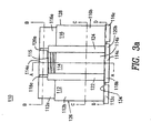
- a removable armor stop 10 of the present invention is shown positioned adjacent to a range taking electrical connector 12. While connector 12 is shown and herein described as having similar components as provided in the commonly assigned and copending U.S. Patent Application Serial No. 08/939,258, incorporated by reference herein, it is contemplated that armor stop 10 may be employed with any range taking electrical connector which may accommodate armor stop 10.
- Connector 12 provides for mechanical and electrical securement of an elongate metal clad cable 14.
- Metal clad cable 14 includes an outer insulative jacket 16 surrounding a scroll type metallic cladding or sheath 18.
- Sheath 18 longitudinally encloses a number of conductors 19 extending through cable 14. These electrical conductors are contemplated as including individually insulated jackets themselves or may simply be uncoated. A portion of jacket 16 at one end of cable 14 may be stripped from its surrounding contact over sheath 18. Sheath 18 may then be cut to provide an annular edge 18a for abutting contact with an internal shoulder 20 of connector 12. Internal shoulder 20 defines an aperture 22 through which the plurality of electrical conductors 19 comprising the contents of cable sheath 18 may pass through so as to exit connector 12 through a cable egress opening 24.
- Connector 12 provides an elongate sealing cavity 26 defined by an internal gland wall 28 and an internal sealing sleeve wall 29. Sealing cavity 26 extends from an area adjacent annular edge 18a to cable egress opening 24.
- Internal shoulder 20 may abuttingly accommodate sheaths of a range of diameters but is generally limited to sheaths having an external diameter greater than the diameter of aperture 22.
- Armor stop 10 is formed to be removably insertable within sealing cavity 26 by threading engagement with threads formed on internal gland wall 28.
- Armor stop 10 is desirably formed of a suitable plastic material such as nylon, polypropylene, or the like.
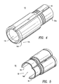
- armor stop 10 is an elongate generally cylindrical member having a cylindrical wall 30, opposed first and second ends 30a and 30b, and a central bore 30c therethrough.
- End 30b includes an annularly enlarged collar 30d thereat.
- End 30b of armor stop 10 is externally screw threaded for screw accommodation with internal gland wall 28 as shown in Figures 1 and 4.
- the upper surface of collar 30d may include a slotted location 30e for accommodating a tool to permit screw insertion of armor stop 10 into cable egress opening 24 of connector 12.
- Elongate channel 32 may be formed as a substantially straight gap between opposing wall edges 34 and 36 as shown in Figures 3a-g and 5. Edges 34 and 36 are desirably formed to deflect if so required to allow conductors 19 to pass through channel 32 into or out of central bore 30c.
- wall 30 may include at least one elongate hinge 40 formed by the closed end of a notch opening towards major surface 31a. Opposing wall edges 34 and 36 are thereby formed on opposing sides, so as to more easily deflect about, of the at least one elongate hinge 40.
- Hinge 40 allows an installer to readily reconfigure armor stop 10 between an open position, shown in Figure 5, so as to allow conductors 19 to pass through channel 32, and a closed position, shown in Figure 4, so as to allow armor stop 10 to achieve a cylindrical configuration and to receive conductors 19 within central bore 30c. Furthermore, in the closed position, armor stop may be removably inserted in the sealing cavity 26 of connector 12. The readiness of the present invention to be opened or closed about conductors 19 of cable 14 provides for easier assembly and potting of a range taking electrical connector.
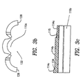
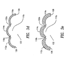
- Figures 3a-g provides details of another armor stop 110 of the present invention.
- Figures 3a and 3b show armor stop 110 in a fully open configuration in which a central bore 10c is accessible to the conductors 19 of cable 14.
- Armor stop 110 includes three elongate arcuate walls 112, 114, and 116 which define central bore 110c.
- Armor stop 110 desirably provides three longitudinally successive and distinct exterior diameters when in the closed configuration.
- the first distinct exterior diameter is provided by wall portions 112a, 114a, and 116a.
- Wall portion 114a may further include one or more elongate threads 115 so as to provide threading engagement between armor stop 110 and internal gland wall 28 of connector 12.
- the second distinct exterior diameter is provided by wall portions 112b, 114b, and 116b.
- the third distinct exterior diameter is provided by wall portions 112c, 114c, and 116c which define an annularly large collar providing an annular stop surface 134 which limits the insertion of armor stop 110 into connector
- Wall 114 connects to wall 112 across a first proximal hinge 118a and a first distal hinge 120a. Wall 114 similarly connects to wall 116 across a second proximal hinge 118b and a second distal hinge 120b.
- Armor stop 110 defines a first elongate window 122 between first hinges 118a and 120a and a second elongate window 124 between second hinges 118b and 120b.
- Wall 112 includes an elongate edge 126 and wall 116 includes an opposed elongate edge 128. Edges 126 and 128 define an elongate channel 132 therebetween through which conductors 19 of cable 14 are received and delivered from central bore 110c. The span of channel 132 between edges 126 and 128 changes as armor stop 110 is reconfigured between an closed configuration to an open configuration.
- armor stop 10 simply entails inserting the armor stop into sealing chamber 26 so that edge 31 is substantially co-planar with internal shoulder 20 so as to increase the range of sizes of cables connector 12 may accommodate. At least a portion of sheath edge 18a abuts armor stop edge 31 so as to properly position cable 14 within connector 12.
- armor stop 10 may be backed out of sealing connector 12 by rotating collar 30d about central bore 30c.
- armor stop 10 may be manually removed from about conductors 19 extending by passing conductors 19 through channel 32.
- conductors 19 of cable 14 may then be potted within sealing cavity 26 using a flowable sealing compound which may fill the void remaining between conductors 19 and internal gland wall 28.
- channel 32 may take other forms as well.
- channel 32 may be formed between overlapping deflectable edges 34 and 36 (not shown).
- channel 32 may be formed as a helical channel formed between opposed deflectable edges 34 and 36 (not shown) and may further include a frangible connecting seam (not shown) which may be opened by transversely pulling one end of edge 34 with respect to the opposed end of edge 36.
- the present invention provides an armor stop with a generally cylindrical configuration where an opening or passage may be established in the wall thereof to permit removal of the stop from its position about an extending electrical conductor without requiring cutting or the use of tools.
Landscapes
- Connector Housings Or Holding Contact Members (AREA)
- Multi-Conductor Connections (AREA)
- Connections Effected By Soldering, Adhesion, Or Permanent Deformation (AREA)
- Details Of Connecting Devices For Male And Female Coupling (AREA)
- Cable Accessories (AREA)
Claims (10)
- Ein entfernbarer Bewehrungsanschlag (10) für einen einen Bereich abdeckenden elektrischen Verbinder (12) zum Abschließen eines Vielleiterkabels (14) einer ersten Größe mit einer Metallumhüllung (18) eines Durchmessers innerhalb eines ersten Bereichs von Durchmessern, wobei der Verbinder (12) ein Verbindergehäuse mit einer Kabeleintrittsöffnung, einer Kabelaustrittsöffnung (24) und einem dazwischen verlaufenden langen Kabeldurchgang aufweist, der Verbinder weiter eine ringförmige Innenschulter (20) aufweist, die in den Kabeldurchgang hinein verläuft und mit der Metallumhüllung (18) des Kabels (14) der ersten Größe eine anliegende Anlage ausbildet, wobei der entfembare Bewehrungsanschlag (10) in die Leiteraustrittsöffnung (24) einführbar ist zum Ausbilden einer anliegenden Anlage mit der Metallumhüllung eines Vielleiterkabels der zweiten Größe mit einem Durchmesser unter dem des Kabels erster Größe, wobei der entfernbare Bewehrungsanschlag folgende Merkmale umfaßt:wobei die Bewehrungsanschlagwand ein in den Verbinderdurchgang einführbares erstes Ende (30a) und eine zwischen den Innen- und Außenflächen festgelegte Stärke aufweist, die die Metallumhüllung des Kabels der zweiten Größe an einem Einführen in den den Leiter aufnehmenden Durchgang hindert, undeine langgestreckte, bogenförmigen Bewehrungsanschlagwand (30) mit entgegengesetzt gerichteten Innen- und Außenflächen, wobei die Innenfläche einen einen Leiter aufnehmenden Durchgang (30c) zur Aufnahme eines oder mehrerer der Leiter des Kabels der zweiten Größe umschließt,die Bewehrungsanschlagwand (30) in Umfangsrichtung gegenüber dem einem oder mehreren der in dem Leiter aufnehmenden Durchgang aufgenommenen Leiter unstetig ausgebildet ist, um in Umfangsrichtung eine Unstetigkeit (32) auszubilden, damit der eine Leiter oder mehrere Leiter durch diese in Umfangsrichtung verlaufende Unstetigkeit (32) durchtreten können.
- Der entfernbare Bewehrungsanschlag (10) nach Anspruch 1, wobei die Außenfläche der Bewehrungsanschlagwand (30) eine Innenfläche des einen Bereich abdeckenden elektrischen Verbinders (12) am Kabeldurchgang erfaßt.
- Der entfernbare Bewehrungsanschlag (10) nach Anspruch 1 oder 2, wobei die Außenfläche der Bewehrungsanschlagwand (30) ein Schraubengewinde aufweist.
- Der entfernbare Bewehrungsanschlag (10) nach irgendeinem der Ansprüche 1 bis 3, weiter mit einem ringförmig vergrößerten Kragen (30d) zum Begrenzen des Einführens des ersten Endes des Bewehrungsanschlags (10) in den abschließenden Durchgang.
- Der entfernbare Bewehrungsanschlag (10) nach irgendeinem der Ansprüche 1 bis 4, wobei die Bewehrungsanschlagwand (30) mindestens eine Kerbe mit einem ein flexibles Gelenk (40) bildenden geschlossenen Ende aufweist, um das sich die Bewehrungsanschlagwand (30) zwischen einer offenen Ausgestaltung, die ein Entfernen des einen oder mehrerer der in dem Leiter aufnehmenden Durchgang aufgenommenen Leiter durch die Bewehrungsanschlagwand zuläßt, und einer geschlossenen Ausgestaltung, die das Einführen des Bewehrungsanschlags in den einen Bereich abdeckenden elektrischen Verbinder zuläßt, biegt.
- Der entfernbare Bewehrungsanschlag (10) nach Anspruch 5, wobei die Bewehrungsanschlagwand (30) mindestens ein langgestrecktes, in Längsrichtung verlaufendes, durch flexible Gelenke begrenztes Fenster ausbildet, um die sich die Bewehrungsanschlagwand (30) zwischen einer offenen Ausgestaltung, die ein Entfernen des einen oder mehrerer der in dem Leiter aufnehmenden Durchgang aufgenommenen Leiter durch die Bewehrungsanschlagwand (30) zuläßt, und einer geschlossenen Ausgestaltung, die das Einführen des Bewehrungsanschlags in den einen Bereich abdeckenden elektrischen Verbinder (12) zuläßt, biegt.
- Der entfernbare Bewehrungsanschlag (10) nach irgendeinem der Ansprüche 1 bis 6, wobei die Bewehrungsanschlagwand (30) weiter in überlappender Deckung miteinander verlaufende, entgegengesetzt gerichtete Längskanten aufweist, um abbiegbar zu sein, damit das Kabel in dem Kabeldurchgang durch diesen durchtreten kann.
- Der entfernbare Bewehrungsanschlag (10) nach irgendeinem der Ansprüche 1 bis 7, wobei die Bewehrungsanschlagwand (30) einen langgestreckten Schlitz zwischen seinen entgegengesetzt gerichteten Längskanten (34, 36) ausbildet, durch den ein oder mehrere Leiter in dem Leiter aufnehmenden Durchgang durchtreten können.
- Der entfernbare Bewehrungsanschlag (10) nach Anspruch 8, wobei die Bewehrungsanschlagwand (30) einen langgestreckten schraubenförmigen Schlitz zwischen seinen entgegengesetzt gerichteten Längskanten ausbildet.
- Der entfernbare Bewehrungsanschlag (10) nach irgendeinem der Ansprüche 1 bis 9, wobei die Bewehrungsanschlagwand (30) ein an der Innenschulter (20) des elektrischen Verbinders (12) anbringbares erstes Ende (30a) zur anliegenden Anlage mit der Umhüllung (18) des Kabels der zweiten Größe aufweist.
Applications Claiming Priority (2)
| Application Number | Priority Date | Filing Date | Title |
|---|---|---|---|
| US7974498P | 1998-03-27 | 1998-03-27 | |
| US79744P | 1998-03-27 |
Publications (3)
| Publication Number | Publication Date |
|---|---|
| EP0945926A2 EP0945926A2 (de) | 1999-09-29 |
| EP0945926A3 EP0945926A3 (de) | 2000-03-08 |
| EP0945926B1 true EP0945926B1 (de) | 2004-12-01 |
Family
ID=22152526
Family Applications (1)
| Application Number | Title | Priority Date | Filing Date |
|---|---|---|---|
| EP99302349A Expired - Lifetime EP0945926B1 (de) | 1998-03-27 | 1999-03-26 | Rüstung Anschlag für einen Stecker für ein Metallplattiertes Kabel |
Country Status (7)
| Country | Link |
|---|---|
| US (1) | US6299485B1 (de) |
| EP (1) | EP0945926B1 (de) |
| JP (1) | JPH11341663A (de) |
| CN (1) | CN1134864C (de) |
| CA (1) | CA2266935C (de) |
| DE (1) | DE69922285T2 (de) |
| ES (1) | ES2234208T3 (de) |
Families Citing this family (9)
| Publication number | Priority date | Publication date | Assignee | Title |
|---|---|---|---|---|
| US7128619B1 (en) | 2004-11-05 | 2006-10-31 | Mcgraw-Edison Company | Connector system and method for securing a cable in a connector system |
| KR101083393B1 (ko) * | 2007-07-10 | 2011-11-14 | 클립퍼 윈드파워, 인코포레이티드 | 버스 바 단부 연결부를 밀봉하기 위한 안전 플러그 |
| CN101599626B (zh) * | 2008-06-04 | 2012-08-29 | 东亚贝斯特株式会社 | 具有铠装部的铠装电缆的连接用电缆索头及铠装部的固定方法 |
| US20110053421A1 (en) * | 2009-08-31 | 2011-03-03 | Mostoller Matthew Edward | Electrical connector for terminating the end of an electrical cable |
| JP5638932B2 (ja) * | 2010-12-21 | 2014-12-10 | 矢崎総業株式会社 | 電子部品内蔵コネクタ |
| USD815604S1 (en) | 2016-02-12 | 2018-04-17 | Bridgeport Fittings, Inc. | Cable armor stop |
| USD771569S1 (en) | 2016-02-12 | 2016-11-15 | Bridgeport Fittings, Inc. | Electrical connector with cable armor stop |
| US10367344B2 (en) | 2016-03-02 | 2019-07-30 | Bridgeport Fittings, Incorporated | Cable armor stop |
| JP7707782B2 (ja) * | 2021-09-10 | 2025-07-15 | 株式会社プロテリアル | 電力ケーブル終端接続部、及び電力ケーブル終端接続部の製造方法 |
Family Cites Families (9)
| Publication number | Priority date | Publication date | Assignee | Title |
|---|---|---|---|---|
| US3671926A (en) * | 1970-08-03 | 1972-06-20 | Lindsay Specialty Prod Ltd | Coaxial cable connector |
| US4963104A (en) * | 1989-05-01 | 1990-10-16 | Spark Innovations, Inc. | Shielded connector assembly |
| FR2655122B1 (fr) * | 1989-11-30 | 1992-03-27 | Souriau & Cie | Joint d'etancheite pour connecteur electrique, et connecteur qui en est equipe. |
| DE4137355C2 (de) * | 1991-11-13 | 1994-04-14 | Contact Gmbh | Elektrischer Steckverbinder für abgeschirmte Kabel |
| US5352134A (en) * | 1993-06-21 | 1994-10-04 | Cabel-Con, Inc. | RF shielded coaxial cable connector |
| US5458507A (en) * | 1993-09-10 | 1995-10-17 | Eft Interests, Ltd. | Fluid resistant electrical connector with boot-type seal assembly |
| DE19529692A1 (de) * | 1995-08-11 | 1997-02-13 | Gore W L & Ass Gmbh | Endgehäuse für einen Steckverbinder |
| JPH1022001A (ja) * | 1996-07-04 | 1998-01-23 | Sumitomo Wiring Syst Ltd | シールド線におけるシールド層の処理構造 |
| US5951327A (en) * | 1997-09-29 | 1999-09-14 | Thomas & Betts International, Inc. | Connector for use with multiple sizes of cables |
-
1999
- 1999-03-23 US US09/274,986 patent/US6299485B1/en not_active Expired - Lifetime
- 1999-03-25 CA CA002266935A patent/CA2266935C/en not_active Expired - Lifetime
- 1999-03-26 ES ES99302349T patent/ES2234208T3/es not_active Expired - Lifetime
- 1999-03-26 EP EP99302349A patent/EP0945926B1/de not_active Expired - Lifetime
- 1999-03-26 DE DE69922285T patent/DE69922285T2/de not_active Expired - Lifetime
- 1999-03-26 JP JP11083977A patent/JPH11341663A/ja active Pending
- 1999-03-29 CN CNB991047435A patent/CN1134864C/zh not_active Expired - Lifetime
Also Published As
| Publication number | Publication date |
|---|---|
| CA2266935C (en) | 2007-03-20 |
| DE69922285D1 (de) | 2005-01-05 |
| JPH11341663A (ja) | 1999-12-10 |
| CN1134864C (zh) | 2004-01-14 |
| CA2266935A1 (en) | 1999-09-27 |
| ES2234208T3 (es) | 2005-06-16 |
| EP0945926A2 (de) | 1999-09-29 |
| DE69922285T2 (de) | 2005-12-22 |
| US6299485B1 (en) | 2001-10-09 |
| CN1230804A (zh) | 1999-10-06 |
| EP0945926A3 (de) | 2000-03-08 |
Similar Documents
| Publication | Publication Date | Title |
|---|---|---|
| EP3410543B1 (de) | Spleissverbinderanordnungen | |
| KR101327578B1 (ko) | 케이블용 연결 용품, 그러한 연결 용품의 커넥터용 홀더, 및 케이블 연결용 키트 | |
| US7568943B2 (en) | Sealing and retaining cable attachment for telecommunications closures | |
| KR100880051B1 (ko) | 전처리가 필요없는 동축 케이블 커넥터 및 이 동축 케이블 커넥터에 동축 케이블을 연결하는 방법 | |
| US6817910B2 (en) | Thermoplastic molded set screw connector assembly | |
| EP1207586B1 (de) | Verbinder für ein semirigides Koaxialkabel | |
| KR101765344B1 (ko) | 냉간 수축 분리가능 커넥터 | |
| US4314094A (en) | Cable seal splice enclosure | |
| EP0945926B1 (de) | Rüstung Anschlag für einen Stecker für ein Metallplattiertes Kabel | |
| KR20070057159A (ko) | 인클로저용 밀봉 부재 | |
| JPH02132781A (ja) | 電気プラグコネクタ用の金属ケーシングスリーブ | |
| EP0970546B1 (de) | Externer erdungsisolations-verbinder für kabelspleissverschlüsse | |
| WO2010084343A2 (en) | Improvements in and relating to electrical connector housings | |
| US20020176674A1 (en) | Fiber optic cable shield bond system | |
| MXPA99002937A (en) | Armor stop for cable connector armored from me | |
| ZA200200165B (en) | Electrical cable gland. | |
| KR200203498Y1 (ko) | 케이블용 관 장치의 수용관 연결구조 | |
| CA1148880A (en) | Cable seal splice enclosure | |
| WO2021118813A1 (en) | Coaxial cable connector termination and splice unit requiring no cable preparation | |
| EP0129353A2 (de) | Kabelverschraubung |
Legal Events
| Date | Code | Title | Description |
|---|---|---|---|
| PUAI | Public reference made under article 153(3) epc to a published international application that has entered the european phase |
Free format text: ORIGINAL CODE: 0009012 |
|
| AK | Designated contracting states |
Kind code of ref document: A2 Designated state(s): BE CH DE ES FR GB IT LI LU NL SE |
|
| AX | Request for extension of the european patent |
Free format text: AL;LT;LV;MK;RO;SI |
|
| PUAL | Search report despatched |
Free format text: ORIGINAL CODE: 0009013 |
|
| AK | Designated contracting states |
Kind code of ref document: A3 Designated state(s): AT BE CH CY DE DK ES FI FR GB GR IE IT LI LU MC NL PT SE |
|
| AX | Request for extension of the european patent |
Free format text: AL;LT;LV;MK;RO;SI |
|
| 17P | Request for examination filed |
Effective date: 20000516 |
|
| AKX | Designation fees paid |
Free format text: BE CH DE ES FR GB IT LI LU NL SE |
|
| RAP1 | Party data changed (applicant data changed or rights of an application transferred) |
Owner name: THOMAS & BETTS INTERNATIONAL, INC. |
|
| 17Q | First examination report despatched |
Effective date: 20030123 |
|
| GRAP | Despatch of communication of intention to grant a patent |
Free format text: ORIGINAL CODE: EPIDOSNIGR1 |
|
| GRAS | Grant fee paid |
Free format text: ORIGINAL CODE: EPIDOSNIGR3 |
|
| GRAA | (expected) grant |
Free format text: ORIGINAL CODE: 0009210 |
|
| AK | Designated contracting states |
Kind code of ref document: B1 Designated state(s): BE CH DE ES FR GB IT LI LU NL SE |
|
| REG | Reference to a national code |
Ref country code: GB Ref legal event code: FG4D |
|
| REG | Reference to a national code |
Ref country code: CH Ref legal event code: EP |
|
| REF | Corresponds to: |
Ref document number: 69922285 Country of ref document: DE Date of ref document: 20050105 Kind code of ref document: P |
|
| REG | Reference to a national code |
Ref country code: CH Ref legal event code: NV Representative=s name: BOVARD AG PATENTANWAELTE |
|
| REG | Reference to a national code |
Ref country code: SE Ref legal event code: TRGR |
|
| REG | Reference to a national code |
Ref country code: ES Ref legal event code: FG2A Ref document number: 2234208 Country of ref document: ES Kind code of ref document: T3 |
|
| ET | Fr: translation filed | ||
| PLBE | No opposition filed within time limit |
Free format text: ORIGINAL CODE: 0009261 |
|
| STAA | Information on the status of an ep patent application or granted ep patent |
Free format text: STATUS: NO OPPOSITION FILED WITHIN TIME LIMIT |
|
| 26N | No opposition filed |
Effective date: 20050902 |
|
| REG | Reference to a national code |
Ref country code: CH Ref legal event code: PFA Owner name: THOMAS & BETTS INTERNATIONAL, INC. Free format text: THOMAS & BETTS INTERNATIONAL, INC.#250 LILLARD DRIVE#SPARKS, NEVADA 89434 (US) -TRANSFER TO- THOMAS & BETTS INTERNATIONAL, INC.#250 LILLARD DRIVE#SPARKS, NEVADA 89434 (US) |
|
| REG | Reference to a national code |
Ref country code: FR Ref legal event code: PLFP Year of fee payment: 18 |
|
| REG | Reference to a national code |
Ref country code: FR Ref legal event code: PLFP Year of fee payment: 19 |
|
| REG | Reference to a national code |
Ref country code: FR Ref legal event code: PLFP Year of fee payment: 20 |
|
| PGFP | Annual fee paid to national office [announced via postgrant information from national office to epo] |
Ref country code: BE Payment date: 20171227 Year of fee payment: 20 |
|
| PGFP | Annual fee paid to national office [announced via postgrant information from national office to epo] |
Ref country code: GB Payment date: 20180321 Year of fee payment: 20 Ref country code: LU Payment date: 20180308 Year of fee payment: 20 Ref country code: DE Payment date: 20180313 Year of fee payment: 20 Ref country code: CH Payment date: 20180314 Year of fee payment: 20 Ref country code: NL Payment date: 20180314 Year of fee payment: 20 |
|
| PGFP | Annual fee paid to national office [announced via postgrant information from national office to epo] |
Ref country code: FR Payment date: 20180223 Year of fee payment: 20 Ref country code: IT Payment date: 20180321 Year of fee payment: 20 Ref country code: SE Payment date: 20180313 Year of fee payment: 20 |
|
| PGFP | Annual fee paid to national office [announced via postgrant information from national office to epo] |
Ref country code: ES Payment date: 20180402 Year of fee payment: 20 |
|
| REG | Reference to a national code |
Ref country code: DE Ref legal event code: R071 Ref document number: 69922285 Country of ref document: DE |
|
| REG | Reference to a national code |
Ref country code: NL Ref legal event code: MK Effective date: 20190325 |
|
| REG | Reference to a national code |
Ref country code: CH Ref legal event code: PL |
|
| REG | Reference to a national code |
Ref country code: GB Ref legal event code: PE20 Expiry date: 20190325 |
|
| PG25 | Lapsed in a contracting state [announced via postgrant information from national office to epo] |
Ref country code: GB Free format text: LAPSE BECAUSE OF EXPIRATION OF PROTECTION Effective date: 20190325 |
|
| REG | Reference to a national code |
Ref country code: BE Ref legal event code: MK Effective date: 20190326 |
|
| REG | Reference to a national code |
Ref country code: ES Ref legal event code: FD2A Effective date: 20200724 |
|
| PG25 | Lapsed in a contracting state [announced via postgrant information from national office to epo] |
Ref country code: ES Free format text: LAPSE BECAUSE OF EXPIRATION OF PROTECTION Effective date: 20190327 |