EP0945397A2 - Fahrzeug mit einem Ausleger wobei eine Zapfwelle durch ein mechanisches Getriebe angetrieben ist - Google Patents
Fahrzeug mit einem Ausleger wobei eine Zapfwelle durch ein mechanisches Getriebe angetrieben ist Download PDFInfo
- Publication number
- EP0945397A2 EP0945397A2 EP99830121A EP99830121A EP0945397A2 EP 0945397 A2 EP0945397 A2 EP 0945397A2 EP 99830121 A EP99830121 A EP 99830121A EP 99830121 A EP99830121 A EP 99830121A EP 0945397 A2 EP0945397 A2 EP 0945397A2
- Authority
- EP
- European Patent Office
- Prior art keywords
- vehicle
- power takeoff
- boom
- longitudinal axis
- internal combustion
- Prior art date
- Legal status (The legal status is an assumption and is not a legal conclusion. Google has not performed a legal analysis and makes no representation as to the accuracy of the status listed.)
- Granted
Links
- 230000009347 mechanical transmission Effects 0.000 title description 3
- 238000002485 combustion reaction Methods 0.000 claims abstract description 10
- 230000005540 biological transmission Effects 0.000 claims abstract description 8
- 239000012530 fluid Substances 0.000 description 2
Images
Classifications
-
- B—PERFORMING OPERATIONS; TRANSPORTING
- B60—VEHICLES IN GENERAL
- B60K—ARRANGEMENT OR MOUNTING OF PROPULSION UNITS OR OF TRANSMISSIONS IN VEHICLES; ARRANGEMENT OR MOUNTING OF PLURAL DIVERSE PRIME-MOVERS IN VEHICLES; AUXILIARY DRIVES FOR VEHICLES; INSTRUMENTATION OR DASHBOARDS FOR VEHICLES; ARRANGEMENTS IN CONNECTION WITH COOLING, AIR INTAKE, GAS EXHAUST OR FUEL SUPPLY OF PROPULSION UNITS IN VEHICLES
- B60K17/00—Arrangement or mounting of transmissions in vehicles
- B60K17/28—Arrangement or mounting of transmissions in vehicles characterised by arrangement, location, or type of power take-off
-
- B—PERFORMING OPERATIONS; TRANSPORTING
- B66—HOISTING; LIFTING; HAULING
- B66F—HOISTING, LIFTING, HAULING OR PUSHING, NOT OTHERWISE PROVIDED FOR, e.g. DEVICES WHICH APPLY A LIFTING OR PUSHING FORCE DIRECTLY TO THE SURFACE OF A LOAD
- B66F9/00—Devices for lifting or lowering bulky or heavy goods for loading or unloading purposes
- B66F9/06—Devices for lifting or lowering bulky or heavy goods for loading or unloading purposes movable, with their loads, on wheels or the like, e.g. fork-lift trucks
- B66F9/065—Devices for lifting or lowering bulky or heavy goods for loading or unloading purposes movable, with their loads, on wheels or the like, e.g. fork-lift trucks non-masted
-
- B—PERFORMING OPERATIONS; TRANSPORTING
- B60—VEHICLES IN GENERAL
- B60Y—INDEXING SCHEME RELATING TO ASPECTS CROSS-CUTTING VEHICLE TECHNOLOGY
- B60Y2200/00—Type of vehicle
- B60Y2200/40—Special vehicles
- B60Y2200/41—Construction vehicles, e.g. graders, excavators
Definitions
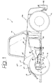
- the present invention relates to a vehicle with a lifting boom, of the type comprising a load-carrying frame having a front section and a rear section, a lifting boom articulated to the frame in the rear section and extending parallel to the longitudinal axis of the vehicle, a control and driving cab arranged on one side of the boom and an internal combustion engine arranged on the opposite side of the boom with respect to the control cab.
- a vehicle of this type is known for example from EP-A-0375705 of the same applicant.
- the engine is arranged with its own longitudinal axis parallel to the longitudinal axis of the vehicle.
- Applicant has already produced vehicles of this type provided with one or two centrally arranged power takeoffs (arranged for instance in the rear and/or front section of the vehicle).
- the power takeoff is operated by a hydraulic motor supplied with a pressurised fluid coming from a hydraulic assembly associated with the internal combustion engine.
- a hydraulic power takeoff is inadequate, in particular for the limited transmissible power.
- the present invention relates to a vehicle of the type mentioned above, characterized in that it comprises a power takeoff mechanically driven by the internal combustion engine, through a mechanical transmission including the rotor of a hydraulic assembly coaxial with the engine and a friction clutch placed downstream of the hydraulic assembly.
- 10 indicates a vehicle provided with a load-carrying frame 12 having a front section 12a and a rear section 12b.
- the frame 12 carries, in a way per se known, a front axle and a rear axle carrying respective front and rear wheels 14, 16 which in the example shown in the figure have all the same diameter and can all be both steering and driving wheels.
- the frame 12 carries a lifting boom 18, preferably telescopic, which is articulated in the rear section 12b of the frame 12 about a transversal axis 20.
- the lifting boom 18 extends parallel to the longitudinal axis of the vehicle and is arranged in a central position. In figure 1 the boom 18 is shown in its completely lowered position. In a way per se known, the boom 18 is provided with a lifting cylinder (not shown) which controls rotations of the boom 18 about the articulation axis 20.
- the boom 18 is provided at its free end with an attachment device 22 to which implements of various type (not shown) such as a fork, a shovel or an aerial platform can be fixed.
- the frame 12 carries a control and driving cab 24 arranged on one side of the lifting boom 18.
- a control and driving cab 24 arranged on one side of the lifting boom 18.
- an internal combustion engine 26 placed between the wheels 14, 16 of that side of the vehicle.
- the engine 26 is arranged with its own longitudinal axis inclined with respect to the longitudinal axis of the vehicle. In the embodiment shown in figure 1, the longitudinal axis of the engine 26 is directed towards the rear section 12b of the frame 12.
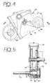
- a three-point hitch generically indicated by 28 is mounted in the rear section 12b of the frame 12, the three-point hitch being provided with a lifting device 30 mounted on a horizontal platform extending between two parallel lateral walls 32, only one of which is visible in figure 1.
- a power takeoff 34 placed in correspondence with the vehicle center line is arranged below said horizontal platform.
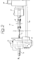
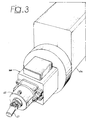
- the power takeoff 34 is directly driven by the engine 26 through a mechanical transmission 36.
- a hydraulic pump 38 of a commercial type is mounted on the output section of the internal combustion engine 26 and its rotor is fixed to the output member of the engine 26.
- the outer housing of the pump 38 is fixed to the engine block 26.
- Hydraulic pipelines (not shown) supply pressurised fluid produced by the pump 38 to distributors and control valves of the various hydraulic devices of the vehicle, including a hydraulic motor which drives the driving wheels by means of a longitudinal transmission shaft connected to the front and rear axle shafts by means of respective differential gears (not shown).
- the rotor of the pump 38 is connected to a cardan shaft 40 through an oil bath multiple-disk friction clutch of a type per se known.
- the cardan shaft 40 is connected to an input shaft 44 of a reduction gear 46.
- the reduction gear 46 comprises two gears 48, 50 which are free to rotate with respect to the input shaft 44 and cooperate with an engagement device 52 which can be manually operated by means of a control lever (not shown).
- the engagement device 52 in a way per se known, enables to selectively connect to the input shaft 44 either the gear 48 or the gear 50.
- the two gears 48, 50 constantly mesh with respective gears 54, 56 fixed to an output shaft forming the power takeoff 34.
- the reduction gear 46 can be provided with a further gear 58 (figures 2 and 4) meshing with one of the gears 54 or 56 fixed to the power takeoff 34.
- This gear 58 can be used for driving a front power takeoff (not shown) by means of a driving shaft 60, which is preferably a cardan shaft, fixed to the gear 58.
Landscapes
- Engineering & Computer Science (AREA)
- Transportation (AREA)
- Mechanical Engineering (AREA)
- Structural Engineering (AREA)
- Chemical & Material Sciences (AREA)
- Combustion & Propulsion (AREA)
- Civil Engineering (AREA)
- Life Sciences & Earth Sciences (AREA)
- Geology (AREA)
- Auxiliary Drives, Propulsion Controls, And Safety Devices (AREA)
- Automatic Cycles, And Cycles In General (AREA)
- Arrangement Of Transmissions (AREA)
Applications Claiming Priority (2)
| Application Number | Priority Date | Filing Date | Title |
|---|---|---|---|
| ITTO980268 ITTO980268A1 (it) | 1998-03-27 | 1998-03-27 | Veicolo con braccio di sollevamento, munito di una presa di forza azionata mediante una trasmissione meccanica |
| ITTO980268 | 1998-03-27 |
Publications (3)
| Publication Number | Publication Date |
|---|---|
| EP0945397A2 true EP0945397A2 (de) | 1999-09-29 |
| EP0945397A3 EP0945397A3 (de) | 2002-04-17 |
| EP0945397B1 EP0945397B1 (de) | 2004-07-21 |
Family
ID=11416640
Family Applications (1)
| Application Number | Title | Priority Date | Filing Date |
|---|---|---|---|
| EP99830121A Expired - Lifetime EP0945397B1 (de) | 1998-03-27 | 1999-03-05 | Fahrzeug mit einem Ausleger wobei eine Zapfwelle durch ein mechanisches Getriebe angetrieben ist |
Country Status (4)
| Country | Link |
|---|---|
| EP (1) | EP0945397B1 (de) |
| DE (1) | DE69918739T2 (de) |
| ES (1) | ES2226328T3 (de) |
| IT (1) | ITTO980268A1 (de) |
Cited By (1)
| Publication number | Priority date | Publication date | Assignee | Title |
|---|---|---|---|---|
| EP1666404A4 (de) * | 2003-09-26 | 2008-07-30 | Mitsubishi Heavy Ind Ltd | Schubgabelstapler |
Citations (1)
| Publication number | Priority date | Publication date | Assignee | Title |
|---|---|---|---|---|
| EP0375705A1 (de) | 1987-07-27 | 1990-07-04 | Merlo Ind Metalmecc | Hebewagen mit einem teleskopischen hebearm. |
Family Cites Families (4)
| Publication number | Priority date | Publication date | Assignee | Title |
|---|---|---|---|---|
| NL7400508A (nl) * | 1974-01-15 | 1975-07-17 | Lely Nv C Van Der | Trekker. |
| FR2438212A1 (fr) * | 1978-10-03 | 1980-04-30 | Fiat Trattori Spa | Dispositif de transmission hydrostatique notamment pour tracteur agricole ou industriel |
| FR2713155B1 (fr) * | 1993-12-01 | 1996-01-26 | Manitou Bf | Chariot élévateur à bras télescopique. |
| CA2153955C (en) * | 1994-07-15 | 2005-01-11 | John Moses | Material-handling vehicle |
-
1998
- 1998-03-27 IT ITTO980268 patent/ITTO980268A1/it unknown
-
1999
- 1999-03-05 EP EP99830121A patent/EP0945397B1/de not_active Expired - Lifetime
- 1999-03-05 ES ES99830121T patent/ES2226328T3/es not_active Expired - Lifetime
- 1999-03-05 DE DE69918739T patent/DE69918739T2/de not_active Expired - Lifetime
Patent Citations (1)
| Publication number | Priority date | Publication date | Assignee | Title |
|---|---|---|---|---|
| EP0375705A1 (de) | 1987-07-27 | 1990-07-04 | Merlo Ind Metalmecc | Hebewagen mit einem teleskopischen hebearm. |
Cited By (1)
| Publication number | Priority date | Publication date | Assignee | Title |
|---|---|---|---|---|
| EP1666404A4 (de) * | 2003-09-26 | 2008-07-30 | Mitsubishi Heavy Ind Ltd | Schubgabelstapler |
Also Published As
| Publication number | Publication date |
|---|---|
| ITTO980268A1 (it) | 1999-09-27 |
| DE69918739T2 (de) | 2005-08-25 |
| EP0945397B1 (de) | 2004-07-21 |
| ES2226328T3 (es) | 2005-03-16 |
| DE69918739D1 (de) | 2004-08-26 |
| EP0945397A3 (de) | 2002-04-17 |
Similar Documents
| Publication | Publication Date | Title |
|---|---|---|
| US6902026B2 (en) | Wheel type traveling and operating vehicle | |
| CN104251289B (zh) | 用于牵引车辆的驱动轴的润滑装置 | |
| US6668964B2 (en) | Automotive vehicle with telescopic load carrying arm | |
| GB2168015A (en) | Transmission arrangement of service vehicle | |
| US8784256B2 (en) | Power divider | |
| EP0113490A1 (de) | Wechselgetriebe für Kraftfahrzeuge | |
| US12072014B2 (en) | Power transmission device for work vehicle | |
| DK156465B (da) | Krafttransmissionsmekanisme til en traktor | |
| US5380255A (en) | Transfer case for part time front wheel drive in a four wheel drive motor vehicle | |
| JPH0211448B2 (de) | ||
| US4019598A (en) | Articulated tractor | |
| EP0945397B1 (de) | Fahrzeug mit einem Ausleger wobei eine Zapfwelle durch ein mechanisches Getriebe angetrieben ist | |
| US3982599A (en) | Tractor having transmission-driven power take-off | |
| EP0945396A2 (de) | Fahrzeug mit einem Ausleger wobei der Motor schräg zur Längsachse des Fahrzeuges angeordened ist | |
| RU76292U1 (ru) | Механизм отбора мощности | |
| US20240367501A1 (en) | Drive train for a work machine, and work machine | |
| JPH06191303A (ja) | トラクタの前車輪伝動装置 | |
| JPH05169995A (ja) | トラクタの伝動装置 | |
| JP3659670B2 (ja) | クローラトラクタのトランスミッション | |
| JP4693370B2 (ja) | 走行作業機における機体構造 | |
| CN100372714C (zh) | 拖拉机 | |
| JPH06877U (ja) | 多目的作業車両の動力分配伝達装置 | |
| EP0108079A1 (de) | Fahrzeugantrieb. | |
| JPH0828650A (ja) | トラクタの変速装置 | |
| EP0153956A1 (de) | Endantriebseinheit für ein fahrzeug |
Legal Events
| Date | Code | Title | Description |
|---|---|---|---|
| PUAI | Public reference made under article 153(3) epc to a published international application that has entered the european phase |
Free format text: ORIGINAL CODE: 0009012 |
|
| AK | Designated contracting states |
Kind code of ref document: A2 Designated state(s): AT BE CH CY DE DK ES FI FR GB GR IE IT LI LU MC NL PT SE Kind code of ref document: A2 Designated state(s): BE CH DE ES FR GB IT LI |
|
| AX | Request for extension of the european patent |
Free format text: AL;LT;LV;MK;RO;SI |
|
| PUAL | Search report despatched |
Free format text: ORIGINAL CODE: 0009013 |
|
| AK | Designated contracting states |
Kind code of ref document: A3 Designated state(s): AT BE CH CY DE DK ES FI FR GB GR IE IT LI LU MC NL PT SE |
|
| AX | Request for extension of the european patent |
Free format text: AL;LT;LV;MK;RO;SI |
|
| RIC1 | Information provided on ipc code assigned before grant |
Free format text: 7B 66F 9/065 A, 7E 02F 3/28 B |
|
| 17P | Request for examination filed |
Effective date: 20020916 |
|
| 17Q | First examination report despatched |
Effective date: 20021122 |
|
| AKX | Designation fees paid |
Free format text: BE CH DE ES FR GB IT LI |
|
| RAP1 | Party data changed (applicant data changed or rights of an application transferred) |
Owner name: MERLO PROJECT S.R.L. |
|
| GRAP | Despatch of communication of intention to grant a patent |
Free format text: ORIGINAL CODE: EPIDOSNIGR1 |
|
| GRAS | Grant fee paid |
Free format text: ORIGINAL CODE: EPIDOSNIGR3 |
|
| GRAA | (expected) grant |
Free format text: ORIGINAL CODE: 0009210 |
|
| AK | Designated contracting states |
Kind code of ref document: B1 Designated state(s): BE CH DE ES FR GB IT LI |
|
| PG25 | Lapsed in a contracting state [announced via postgrant information from national office to epo] |
Ref country code: LI Free format text: LAPSE BECAUSE OF FAILURE TO SUBMIT A TRANSLATION OF THE DESCRIPTION OR TO PAY THE FEE WITHIN THE PRESCRIBED TIME-LIMIT Effective date: 20040721 Ref country code: CH Free format text: LAPSE BECAUSE OF FAILURE TO SUBMIT A TRANSLATION OF THE DESCRIPTION OR TO PAY THE FEE WITHIN THE PRESCRIBED TIME-LIMIT Effective date: 20040721 Ref country code: BE Free format text: LAPSE BECAUSE OF FAILURE TO SUBMIT A TRANSLATION OF THE DESCRIPTION OR TO PAY THE FEE WITHIN THE PRESCRIBED TIME-LIMIT Effective date: 20040721 |
|
| REG | Reference to a national code |
Ref country code: GB Ref legal event code: FG4D |
|
| REG | Reference to a national code |
Ref country code: CH Ref legal event code: EP |
|
| REG | Reference to a national code |
Ref country code: IE Ref legal event code: FG4D |
|
| REF | Corresponds to: |
Ref document number: 69918739 Country of ref document: DE Date of ref document: 20040826 Kind code of ref document: P |
|
| REG | Reference to a national code |
Ref country code: CH Ref legal event code: PL |
|
| REG | Reference to a national code |
Ref country code: ES Ref legal event code: FG2A Ref document number: 2226328 Country of ref document: ES Kind code of ref document: T3 |
|
| PLBE | No opposition filed within time limit |
Free format text: ORIGINAL CODE: 0009261 |
|
| STAA | Information on the status of an ep patent application or granted ep patent |
Free format text: STATUS: NO OPPOSITION FILED WITHIN TIME LIMIT |
|
| ET | Fr: translation filed | ||
| 26N | No opposition filed |
Effective date: 20050422 |
|
| REG | Reference to a national code |
Ref country code: FR Ref legal event code: PLFP Year of fee payment: 18 |
|
| REG | Reference to a national code |
Ref country code: FR Ref legal event code: PLFP Year of fee payment: 19 |
|
| REG | Reference to a national code |
Ref country code: FR Ref legal event code: PLFP Year of fee payment: 20 |
|
| PGFP | Annual fee paid to national office [announced via postgrant information from national office to epo] |
Ref country code: GB Payment date: 20180329 Year of fee payment: 20 |
|
| PGFP | Annual fee paid to national office [announced via postgrant information from national office to epo] |
Ref country code: FR Payment date: 20180329 Year of fee payment: 20 Ref country code: IT Payment date: 20180315 Year of fee payment: 20 |
|
| PGFP | Annual fee paid to national office [announced via postgrant information from national office to epo] |
Ref country code: ES Payment date: 20180423 Year of fee payment: 20 Ref country code: DE Payment date: 20180530 Year of fee payment: 20 |
|
| REG | Reference to a national code |
Ref country code: DE Ref legal event code: R071 Ref document number: 69918739 Country of ref document: DE |
|
| REG | Reference to a national code |
Ref country code: GB Ref legal event code: PE20 Expiry date: 20190304 |
|
| PG25 | Lapsed in a contracting state [announced via postgrant information from national office to epo] |
Ref country code: GB Free format text: LAPSE BECAUSE OF EXPIRATION OF PROTECTION Effective date: 20190304 |
|
| REG | Reference to a national code |
Ref country code: ES Ref legal event code: FD2A Effective date: 20200803 |
|
| PG25 | Lapsed in a contracting state [announced via postgrant information from national office to epo] |
Ref country code: ES Free format text: LAPSE BECAUSE OF EXPIRATION OF PROTECTION Effective date: 20190306 |
|
| P01 | Opt-out of the competence of the unified patent court (upc) registered |
Effective date: 20230529 |