EP0945189A2 - Siebrost - Google Patents
Siebrost Download PDFInfo
- Publication number
- EP0945189A2 EP0945189A2 EP99103822A EP99103822A EP0945189A2 EP 0945189 A2 EP0945189 A2 EP 0945189A2 EP 99103822 A EP99103822 A EP 99103822A EP 99103822 A EP99103822 A EP 99103822A EP 0945189 A2 EP0945189 A2 EP 0945189A2
- Authority
- EP
- European Patent Office
- Prior art keywords
- grate
- sieve
- profile
- bar
- bars
- Prior art date
- Legal status (The legal status is an assumption and is not a legal conclusion. Google has not performed a legal analysis and makes no representation as to the accuracy of the status listed.)
- Granted
Links
Images


Classifications
-
- B—PERFORMING OPERATIONS; TRANSPORTING
- B07—SEPARATING SOLIDS FROM SOLIDS; SORTING
- B07B—SEPARATING SOLIDS FROM SOLIDS BY SIEVING, SCREENING, SIFTING OR BY USING GAS CURRENTS; SEPARATING BY OTHER DRY METHODS APPLICABLE TO BULK MATERIAL, e.g. LOOSE ARTICLES FIT TO BE HANDLED LIKE BULK MATERIAL
- B07B1/00—Sieving, screening, sifting, or sorting solid materials using networks, gratings, grids, or the like
- B07B1/46—Constructional details of screens in general; Cleaning or heating of screens
- B07B1/4609—Constructional details of screens in general; Cleaning or heating of screens constructional details of screening surfaces or meshes
- B07B1/4681—Meshes of intersecting, non-woven, elements
-
- B—PERFORMING OPERATIONS; TRANSPORTING
- B07—SEPARATING SOLIDS FROM SOLIDS; SORTING
- B07B—SEPARATING SOLIDS FROM SOLIDS BY SIEVING, SCREENING, SIFTING OR BY USING GAS CURRENTS; SEPARATING BY OTHER DRY METHODS APPLICABLE TO BULK MATERIAL, e.g. LOOSE ARTICLES FIT TO BE HANDLED LIKE BULK MATERIAL
- B07B1/00—Sieving, screening, sifting, or sorting solid materials using networks, gratings, grids, or the like
- B07B1/12—Apparatus having only parallel elements
Definitions
- the invention relates to a sieve grate for separating Bulk goods with grate bars arranged side by side, that form gaps between themselves and those on crossbars are attached.
- Conventional sieve grids for rough separation of Bulk goods consist of crossbeams with larger ones Distances and screwed or screwed or on or welded-on grate bars with smaller distances. According to the arrangement of the crossbars and the Rust bars result in gaps.
- the grates can be arranged with an inclination and / or in steps.
- the material of these gratings is made of steel. Are the grates screwed together, so are assembly and disassembly complex. If they are welded together, there is assembly and disassembly also complex and it can not individual grate bars to be replaced, but it must the entire welded frame can be replaced. There is also a risk of rust formation. For softer ones materials to be screened / dewatered (for Example root crops such as potatoes, beets, etc.) damage from the hard materials.
- the object of the invention is in a sieve grid Production, assembly, disassembly and simplify and improve maintenance and to achieve high operational reliability.
- this object is achieved by that the grate bars on the crossbar are positive are releasably attached.
- Such a grate screen is particularly easy to manufacture and preferably to be assembled without tools. In particular, it has high operational reliability and an easy repair on.
- the grate has at least two crossbeams 1 and 1 releasably attached grate bars 2.
- the one for crossbeams and grate bars used is rubber-elastic preferably polyurethane 5.
- the cross beams and the Grate bars can be provided with reinforcements.
- the Crossbars contain open ones Mounting recesses 6 in which the grate bars 2 from Be pushed in from above.
- One in particular sawtooth-shaped locking recess 7 in the Mounting recess 6 in the crossbar 1 and a Locking projection 8 of the same cross section on Grate bar 2 prevent accidental loosening by the application vibration could occur.
- the gap length is determined by the distance between the Crossbar determined.
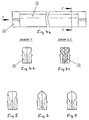
- the grate bars 2 preferably have a profile tapering downward in cross section Gap area to avoid the jamming of boundary grain. For further protection of "soft" screenings and for the head profile of the Grate bar preferably be rounded (Fig. 4, 5, 6).
- the mounting profile 9 is preferably at the end arranged at the ends of the grate bars 2.
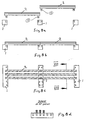
- the Mounting profiles 9 can also be centered on the grate bars 2 to be appropriate. This is the top of the Crossbar 1 and that of the grate bars 2 on one level. To increase the open screen area, the The mounting profiles on the grate bars protrude downwards (Fig. 8a). The grate bars run when assembled then over the crossbar, which is such a continuous Form a gap.
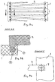
- Mounting profile 9 is angular. But as soon as one conical gap course is necessary, this is achieved through tapering training in the direction of conveyance the grate bars and / or by a widening one another Arrangement of the grate bars (Fig. 9, 10) so that the columns widen between the grate bars.
- Mounting profile preferably round, especially cylindrical (Fig. 9, 10) formed, that is, the mounting profiles are down (Fig. 9a to 9c) or face (Fig. 10a to 10c) parts protruding from the grate bars, especially cones with in particular round horizontal cross section and in particular cylindrical shape with vertical cylinder axis. In order to distribution of the screenings is achieved at the same time.
- FIG. 2a and 2b can preferably in the lower area of the grate bars on one or both sides Spacer knobs (3a and 3b) must be worked in on the side.
- the Flank slope 3-20 degrees, preferably 5-10 degrees should and the mounting profile with an oversize is to ensure a secure hold on the crossbeam to reach.
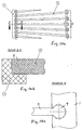
- horizontal Collar bolts 11 are provided, each half in semi-cylindrical recesses of the mounting profile 9 and the mounting recess 6 on both sides of the mounting profile insert and therefore preferably the Locking projection 8 and the locking recess 7 replace.
- Vertical drainage or cleaning openings 10 extend from the bottom of the locking recess down through the crossbar.
- the mounting profiles under the Profile bars may be arranged. As a result, the Crossbeam below the profile bars.
- the recesses and mounting profiles are subject to stress conical.
Landscapes
- Combined Means For Separation Of Solids (AREA)
Abstract
Description
- Fig. 1a
- eine Seitenansicht einer ersten Ausführungsform,
- Fig. 1b
- eine Ansicht nach A-A in Fig. 1a
- Fig. 1c
- einen Ausschnitt aus Fig. 1b,
- Fig. 2a
- eine Draufsicht auf eine zweite Ausführungsform,
- Fig. 2b
- eine Ansicht nach B-B in Fig. 2a,
- Fig. 3
- Seitenansichten dreier Ausführungsformen,
- Fig. 4a
- eine Seitenansicht eines Roststabes,
- Fig. 4b
- eine Stirnansiht nach Pfeil Y in Fig. 4a,
- Fig. 4c
- einen Schnitt C-C in Fig. 4a,
- Fig. 5 bis 7
- eine Stirnansicht des Montageprofils in alternativen Formen,
- Fig. 8a
- einen Siebrost mit abgenommenen Roststäben,
- Fig. 8b
- einen Siebrost mit aufgesetzten Roststäben,
- Fig. 8c
- eine Draufsicht auf den Siebrost nach Fig. 8b,
- Fig. 8d
- einen senkrechten Schnitt nach VIII - VIII in Fig. 8c,
- Fig. 9a
- einen Siebrost mit einander sich weitenden Roststäben,
- Fig. 9b
- einen Schnitt durch den Siebrost nach D-D in Fig. 9a,
- Fig. 9c
- den Ausschnitt Z in Fig, 9a in Vergrößerung,
- Fig. 10a
- einen Siebrost mit teilzylindrischen Roststabenden,
- Fig. 10b
- einen Schnitt nach E-E in Fig. 10a,
- Fig. 10c
- den Ausschnitt W in Fig. 10a in Vergrößerung,
- Fig. 11a
- eine Seitenansicht eines Befestigungsbolzens,
- Fig. 11b
- einen senkrechten Schnitt durch einen Querbalken mit zwei Roststäben,
- Fig. 11c
- einen Schnitt nach F-F in Fig. 11a,
- Fig. 12
- einen Roststab mit Montageprofilen in einem Abstand zu den Roststabenden, wobei ein Profil nach unten vorsteht.
Claims (15)
- Siebrost zum Trennen von Schüttgütern mit nebeneinander angeordneten Roststäben (2), die zwischen sich Spalten (2a) bilden und die an Querbalken (1) befestigt sind, dadurch gekennzeichnet, daß die Roststäbe (2) an den Querbalken (1) formschlüssig lösbar befestigt sind.
- Siebrost nach Anspruch 1, dadurch gekennzeichnet, daß die lösbare Verbindung zwischen den Roststäben (2) und die Querbalken (1) eine Rastverbindung aufweisen.
- Siebrost nach Anspruch 2, dadurch gekennzeichnet, daß die Roststäbe (2) und die Querbalken (1) Rastausnehmungen (7) und darin einliegende Rastvorsprünge (8) gleicher Größe und Form aufweisen.
- Siebrost nach einem der vorherigen Ansprüche, dadurch gekennzeichnet, daß für die formschlüssige Verbindung der Roststab einen Montagebereich (9) aufweist, der in einer Montageausnehmung (6) des Querbalkens (1) einliegt.
- Siebrost nach Anspruch 4, dadurch gekennzeichnet, daß die Montageausnehmungen (6) Arretierungsausnehmungen und/oder Arretierungsvorsprünge aufweisen, die mit entsprechenden Arretierungsvorsprüngen und/oder Arretierungsausnehmungen der Roststäbe korrespondieren.
- Siebrost nach Anspruch 4 oder 5, dadurch gekennzeichnet, daß der Montagebereich des Roststabes (2) von einem profilförmigen Abschnitt (9) am Ende des Roststabes gebildet ist, wobei dieser Abschnitt den Raststab stirnseitig verlängert.
- Siebrost nach Anspruch 6, dadurch gekennzeichnet, daß der profilförmige Abschnitt (9) ein mit dem Roststabprofil fluchtendes oder paralleles Profil bildet.
- Siebrost nach Anspruch 6, dadurch gekennzeichnet, daß der profilförmige Abschnitt (9) ein zum Roststabprofil quer angeordnetes Profil bildet.
- Siebrost nach Anspruch 8, dadurch gekennzeichnet, daß der profilförmige Abschnitt (9) einen rechteckigen, runden oder ovalen Querschnitt aufweist.
- Siebrost nach Anspruch 4 oder 5, dadurch gekennzeichnet, daß der Montagebereich des Roststabes (2) ein an der Unterseite des Roststabes vorstehender Vorsprung (9) ist.
- Siebrost nach Anspruch 10, dadurch gekennzeichnet, daß der Vorsprung (9) einen rechteckigen, runden oder ovalen Querschnitt aufweist.
- Siebrost nach einem der Ansprüche 4 bis 11, dadurch gekennzeichnet, daß bei einem sicheren Halt des Montagebereiches (9) des Roststabes (2) in der Montageausnehmung (6) des Querbalkens (1) Bolzen (11), insbesondere Bundbolzen zwischen den Teilen im Bereich der Berührungsflächen angeordnet sind.
- Siebrost nach einem der vorherigen Ansprüche, dadurch gekennzeichnet, daß an den Roststäben seitlich Distanznoppen (3a, 3b) vorstehen.
- Siebrost nach einem der vorherigen Ansprüche, dadurch gekennzeichnet, daß die Querbalken (1) und/oder Roststäbe (2) aus Kunststoff, insbesondere aus Polyurethan bestehen.
- Siebrost nach Anspruch 14, dadurch gekennzeichnet, daß in dem Kunststoff der Roststäbe (2) und/oder der Querbalken (1) Armierungen, insbesondere aus Metall angeordnet sind.
Priority Applications (1)
| Application Number | Priority Date | Filing Date | Title |
|---|---|---|---|
| DE29924351U DE29924351U1 (de) | 1998-03-25 | 1999-02-27 | Siebrost |
Applications Claiming Priority (2)
| Application Number | Priority Date | Filing Date | Title |
|---|---|---|---|
| DE19813006 | 1998-03-25 | ||
| DE19813006 | 1998-03-25 |
Publications (3)
| Publication Number | Publication Date |
|---|---|
| EP0945189A2 true EP0945189A2 (de) | 1999-09-29 |
| EP0945189A3 EP0945189A3 (de) | 2000-05-31 |
| EP0945189B1 EP0945189B1 (de) | 2002-07-17 |
Family
ID=7862187
Family Applications (1)
| Application Number | Title | Priority Date | Filing Date |
|---|---|---|---|
| EP99103822A Expired - Lifetime EP0945189B1 (de) | 1998-03-25 | 1999-02-27 | Siebrost |
Country Status (2)
| Country | Link |
|---|---|
| EP (1) | EP0945189B1 (de) |
| DE (2) | DE19904091A1 (de) |
Cited By (5)
| Publication number | Priority date | Publication date | Assignee | Title |
|---|---|---|---|---|
| EP1230987A1 (de) * | 2001-02-13 | 2002-08-14 | Isenmann Siebe GmbH | Sieb mit spalt- oder schlitzförmigen Sieböffnungen |
| WO2008150850A1 (en) * | 2007-05-29 | 2008-12-11 | Blueline Enterprises, Inc. | Material separator |
| EP1726370A3 (de) * | 2005-05-25 | 2009-06-17 | Isenmann Siebe GmbH | Siebfläche mit Stangenrost |
| EP3023165A1 (de) * | 2014-11-19 | 2016-05-25 | Stocker Mechatronik GmbH | Spaltsieb |
| EP3520908A3 (de) * | 2018-01-23 | 2019-09-11 | Terex GB Limited | Siebstabanordnung für ein sieb |
Families Citing this family (2)
| Publication number | Priority date | Publication date | Assignee | Title |
|---|---|---|---|---|
| FR2815548B1 (fr) * | 2000-10-25 | 2003-08-15 | Technos Et Cie | Grille de separation pour separer des corps nettoyants d'un fluide et dispositif comprenant une telle grille |
| DE102007008447A1 (de) * | 2007-02-19 | 2008-04-17 | Tegel Technik Gmbh | Rüttelkörper für eine Sortiervorrichtung |
Family Cites Families (4)
| Publication number | Priority date | Publication date | Assignee | Title |
|---|---|---|---|---|
| DE1126331B (de) * | 1961-04-19 | 1962-03-22 | Hewitt Robins Internat S A | Ruettelsieb |
| US3901801A (en) * | 1974-06-17 | 1975-08-26 | Hendrick Mfg Co | Industrial screen |
| US4381235A (en) * | 1980-11-20 | 1983-04-26 | Powerscreen Limited | Screening apparatus |
| SE443302B (sv) * | 1980-11-24 | 1986-02-24 | Berglunds Mek Ab | Sorteringsanordning for schaktmassor |
-
1999
- 1999-02-02 DE DE19904091A patent/DE19904091A1/de not_active Withdrawn
- 1999-02-27 EP EP99103822A patent/EP0945189B1/de not_active Expired - Lifetime
- 1999-02-27 DE DE59902011T patent/DE59902011D1/de not_active Expired - Fee Related
Cited By (7)
| Publication number | Priority date | Publication date | Assignee | Title |
|---|---|---|---|---|
| EP1230987A1 (de) * | 2001-02-13 | 2002-08-14 | Isenmann Siebe GmbH | Sieb mit spalt- oder schlitzförmigen Sieböffnungen |
| DE10106499A1 (de) * | 2001-02-13 | 2002-08-29 | Isenmann Siebe Gmbh | Sieb mit spalt- oder schlitzförmigen Sieböffnungen |
| EP1726370A3 (de) * | 2005-05-25 | 2009-06-17 | Isenmann Siebe GmbH | Siebfläche mit Stangenrost |
| WO2008150850A1 (en) * | 2007-05-29 | 2008-12-11 | Blueline Enterprises, Inc. | Material separator |
| EP3023165A1 (de) * | 2014-11-19 | 2016-05-25 | Stocker Mechatronik GmbH | Spaltsieb |
| EP3520908A3 (de) * | 2018-01-23 | 2019-09-11 | Terex GB Limited | Siebstabanordnung für ein sieb |
| US11198156B2 (en) | 2018-01-23 | 2021-12-14 | Terex Gb Limited | Screening bar assembly for a screen |
Also Published As
| Publication number | Publication date |
|---|---|
| EP0945189A3 (de) | 2000-05-31 |
| DE59902011D1 (de) | 2002-08-22 |
| DE19904091A1 (de) | 1999-09-30 |
| EP0945189B1 (de) | 2002-07-17 |
Similar Documents
| Publication | Publication Date | Title |
|---|---|---|
| DE3390381C2 (de) | Siebvorrichtung, umfassend eine Vielzahl vonSiebbausteinen | |
| DE10083850T5 (de) | Montagesystem für modulare in einem Filterboden verwendete Platten | |
| WO1981002398A1 (fr) | Plaque perforee autonettoyante pour crible oscillant | |
| DE3114574A1 (de) | Vibrationssieb mit einer einrichtung zum beseitigen der verstopfung des siebbodens | |
| DE1295579B (de) | Vorrichtung zum UEberbruecken von Dehnungsfugen, insbesondere in Bruecken | |
| DE4303892C2 (de) | Siebbelag | |
| EP0945189B1 (de) | Siebrost | |
| EP1544377B1 (de) | Schalungselement einer Rundschalung | |
| DE2832747B1 (de) | Siebdeck | |
| DE2754044B1 (de) | Industrie-Siebboden zur Aufbereitung von Schuettguetern | |
| DE102013018467B4 (de) | Siebmaschine | |
| DE2634934B2 (de) | Plattenartiges Siebelement | |
| DE4300303A1 (de) | Spannsieb | |
| DE3307677A1 (de) | Siebtrommel, insbesondere fuer siebzentrifugen | |
| CH627379A5 (en) | Screen | |
| DE2706277C3 (de) | Siebboden | |
| DE29924351U1 (de) | Siebrost | |
| DE8904477U1 (de) | Siebboden | |
| DE1156723B (de) | Siebrost | |
| DE2364297A1 (de) | Balkenfoermiges bauelement | |
| DE602004011125T2 (de) | Strukturelle anordnung für schwingeinrichtungen | |
| DE1162782B (de) | Siebrost | |
| EP0641608A2 (de) | Siebmaschine | |
| DE3304679C1 (de) | Siebbelag mit übereinander angeordneten Siebböden | |
| DE19844015B4 (de) | Einstückig aus Kunststoff hergestellter Transportkasten |
Legal Events
| Date | Code | Title | Description |
|---|---|---|---|
| PUAI | Public reference made under article 153(3) epc to a published international application that has entered the european phase |
Free format text: ORIGINAL CODE: 0009012 |
|
| AK | Designated contracting states |
Kind code of ref document: A2 Designated state(s): BE DE DK ES FR GB IT NL |
|
| AX | Request for extension of the european patent |
Free format text: AL;LT;LV;MK;RO PAYMENT 19990227;SI PAYMENT 19990227 |
|
| PUAL | Search report despatched |
Free format text: ORIGINAL CODE: 0009013 |
|
| AK | Designated contracting states |
Kind code of ref document: A3 Designated state(s): AT BE CH CY DE DK ES FI FR GB GR IE IT LI LU MC NL PT SE |
|
| AX | Request for extension of the european patent |
Free format text: AL;LT;LV;MK;RO PAYMENT 19990227;SI PAYMENT 19990227 |
|
| AKX | Designation fees paid |
Free format text: BE DE DK ES FR GB IT NL |
|
| AXX | Extension fees paid |
Free format text: RO PAYMENT 19990227;SI PAYMENT 19990227 |
|
| 17P | Request for examination filed |
Effective date: 20001018 |
|
| GRAG | Despatch of communication of intention to grant |
Free format text: ORIGINAL CODE: EPIDOS AGRA |
|
| 17Q | First examination report despatched |
Effective date: 20011129 |
|
| GRAG | Despatch of communication of intention to grant |
Free format text: ORIGINAL CODE: EPIDOS AGRA |
|
| GRAH | Despatch of communication of intention to grant a patent |
Free format text: ORIGINAL CODE: EPIDOS IGRA |
|
| GRAH | Despatch of communication of intention to grant a patent |
Free format text: ORIGINAL CODE: EPIDOS IGRA |
|
| GRAA | (expected) grant |
Free format text: ORIGINAL CODE: 0009210 |
|
| AK | Designated contracting states |
Kind code of ref document: B1 Designated state(s): BE DE DK ES FR GB IT NL |
|
| AX | Request for extension of the european patent |
Free format text: RO PAYMENT 19990227;SI PAYMENT 19990227 |
|
| PG25 | Lapsed in a contracting state [announced via postgrant information from national office to epo] |
Ref country code: IT Free format text: LAPSE BECAUSE OF FAILURE TO SUBMIT A TRANSLATION OF THE DESCRIPTION OR TO PAY THE FEE WITHIN THE PRESCRIBED TIME-LIMIT;WARNING: LAPSES OF ITALIAN PATENTS WITH EFFECTIVE DATE BEFORE 2007 MAY HAVE OCCURRED AT ANY TIME BEFORE 2007. THE CORRECT EFFECTIVE DATE MAY BE DIFFERENT FROM THE ONE RECORDED. Effective date: 20020717 |
|
| REG | Reference to a national code |
Ref country code: GB Ref legal event code: FG4D Free format text: NOT ENGLISH |
|
| REF | Corresponds to: |
Ref document number: 59902011 Country of ref document: DE Date of ref document: 20020822 |
|
| GBT | Gb: translation of ep patent filed (gb section 77(6)(a)/1977) |
Effective date: 20020813 |
|
| PG25 | Lapsed in a contracting state [announced via postgrant information from national office to epo] |
Ref country code: DK Free format text: LAPSE BECAUSE OF FAILURE TO SUBMIT A TRANSLATION OF THE DESCRIPTION OR TO PAY THE FEE WITHIN THE PRESCRIBED TIME-LIMIT Effective date: 20021017 |
|
| ET | Fr: translation filed | ||
| PG25 | Lapsed in a contracting state [announced via postgrant information from national office to epo] |
Ref country code: ES Free format text: LAPSE BECAUSE OF FAILURE TO SUBMIT A TRANSLATION OF THE DESCRIPTION OR TO PAY THE FEE WITHIN THE PRESCRIBED TIME-LIMIT Effective date: 20030130 |
|
| PLBI | Opposition filed |
Free format text: ORIGINAL CODE: 0009260 |
|
| PLBQ | Unpublished change to opponent data |
Free format text: ORIGINAL CODE: EPIDOS OPPO |
|
| PLBF | Reply of patent proprietor to notice(s) of opposition |
Free format text: ORIGINAL CODE: EPIDOS OBSO |
|
| 26 | Opposition filed |
Opponent name: GUMMI KUEPER GMBH & CO KG Effective date: 20030417 |
|
| NLR1 | Nl: opposition has been filed with the epo |
Opponent name: GUMMI KUEPER GMBH & CO KG |
|
| PLAX | Notice of opposition and request to file observation + time limit sent |
Free format text: ORIGINAL CODE: EPIDOSNOBS2 |
|
| PLBB | Reply of patent proprietor to notice(s) of opposition received |
Free format text: ORIGINAL CODE: EPIDOSNOBS3 |
|
| PLCK | Communication despatched that opposition was rejected |
Free format text: ORIGINAL CODE: EPIDOSNREJ1 |
|
| PLBN | Opposition rejected |
Free format text: ORIGINAL CODE: 0009273 |
|
| STAA | Information on the status of an ep patent application or granted ep patent |
Free format text: STATUS: OPPOSITION REJECTED |
|
| 27O | Opposition rejected |
Effective date: 20040619 |
|
| NLR2 | Nl: decision of opposition |
Effective date: 20040619 |
|
| PGFP | Annual fee paid to national office [announced via postgrant information from national office to epo] |
Ref country code: NL Payment date: 20050203 Year of fee payment: 7 |
|
| PGFP | Annual fee paid to national office [announced via postgrant information from national office to epo] |
Ref country code: FR Payment date: 20050208 Year of fee payment: 7 |
|
| PGFP | Annual fee paid to national office [announced via postgrant information from national office to epo] |
Ref country code: GB Payment date: 20050223 Year of fee payment: 7 |
|
| PGFP | Annual fee paid to national office [announced via postgrant information from national office to epo] |
Ref country code: DE Payment date: 20050224 Year of fee payment: 7 |
|
| PGFP | Annual fee paid to national office [announced via postgrant information from national office to epo] |
Ref country code: BE Payment date: 20050408 Year of fee payment: 7 |
|
| PG25 | Lapsed in a contracting state [announced via postgrant information from national office to epo] |
Ref country code: GB Free format text: LAPSE BECAUSE OF NON-PAYMENT OF DUE FEES Effective date: 20060227 |
|
| PG25 | Lapsed in a contracting state [announced via postgrant information from national office to epo] |
Ref country code: BE Free format text: LAPSE BECAUSE OF NON-PAYMENT OF DUE FEES Effective date: 20060228 |
|
| PG25 | Lapsed in a contracting state [announced via postgrant information from national office to epo] |
Ref country code: NL Free format text: LAPSE BECAUSE OF NON-PAYMENT OF DUE FEES Effective date: 20060901 Ref country code: DE Free format text: LAPSE BECAUSE OF NON-PAYMENT OF DUE FEES Effective date: 20060901 |
|
| GBPC | Gb: european patent ceased through non-payment of renewal fee |
Effective date: 20060227 |
|
| NLV4 | Nl: lapsed or anulled due to non-payment of the annual fee |
Effective date: 20060901 |
|
| REG | Reference to a national code |
Ref country code: FR Ref legal event code: ST Effective date: 20061031 |
|
| BERE | Be: lapsed |
Owner name: *ISENMANN SIEBE G.M.B.H. Effective date: 20060228 |
|
| PG25 | Lapsed in a contracting state [announced via postgrant information from national office to epo] |
Ref country code: FR Free format text: LAPSE BECAUSE OF NON-PAYMENT OF DUE FEES Effective date: 20060228 |