EP0945189A2 - Sieve grate - Google Patents
Sieve grate Download PDFInfo
- Publication number
- EP0945189A2 EP0945189A2 EP99103822A EP99103822A EP0945189A2 EP 0945189 A2 EP0945189 A2 EP 0945189A2 EP 99103822 A EP99103822 A EP 99103822A EP 99103822 A EP99103822 A EP 99103822A EP 0945189 A2 EP0945189 A2 EP 0945189A2
- Authority
- EP
- European Patent Office
- Prior art keywords
- grate
- sieve
- profile
- bar
- bars
- Prior art date
- Legal status (The legal status is an assumption and is not a legal conclusion. Google has not performed a legal analysis and makes no representation as to the accuracy of the status listed.)
- Granted
Links
Images


Classifications
-
- B—PERFORMING OPERATIONS; TRANSPORTING
- B07—SEPARATING SOLIDS FROM SOLIDS; SORTING
- B07B—SEPARATING SOLIDS FROM SOLIDS BY SIEVING, SCREENING, SIFTING OR BY USING GAS CURRENTS; SEPARATING BY OTHER DRY METHODS APPLICABLE TO BULK MATERIAL, e.g. LOOSE ARTICLES FIT TO BE HANDLED LIKE BULK MATERIAL
- B07B1/00—Sieving, screening, sifting, or sorting solid materials using networks, gratings, grids, or the like
- B07B1/46—Constructional details of screens in general; Cleaning or heating of screens
- B07B1/4609—Constructional details of screens in general; Cleaning or heating of screens constructional details of screening surfaces or meshes
- B07B1/4681—Meshes of intersecting, non-woven, elements
-
- B—PERFORMING OPERATIONS; TRANSPORTING
- B07—SEPARATING SOLIDS FROM SOLIDS; SORTING
- B07B—SEPARATING SOLIDS FROM SOLIDS BY SIEVING, SCREENING, SIFTING OR BY USING GAS CURRENTS; SEPARATING BY OTHER DRY METHODS APPLICABLE TO BULK MATERIAL, e.g. LOOSE ARTICLES FIT TO BE HANDLED LIKE BULK MATERIAL
- B07B1/00—Sieving, screening, sifting, or sorting solid materials using networks, gratings, grids, or the like
- B07B1/12—Apparatus having only parallel elements
Definitions
- the invention relates to a sieve grate for separating Bulk goods with grate bars arranged side by side, that form gaps between themselves and those on crossbars are attached.
- Conventional sieve grids for rough separation of Bulk goods consist of crossbeams with larger ones Distances and screwed or screwed or on or welded-on grate bars with smaller distances. According to the arrangement of the crossbars and the Rust bars result in gaps.
- the grates can be arranged with an inclination and / or in steps.
- the material of these gratings is made of steel. Are the grates screwed together, so are assembly and disassembly complex. If they are welded together, there is assembly and disassembly also complex and it can not individual grate bars to be replaced, but it must the entire welded frame can be replaced. There is also a risk of rust formation. For softer ones materials to be screened / dewatered (for Example root crops such as potatoes, beets, etc.) damage from the hard materials.
- the object of the invention is in a sieve grid Production, assembly, disassembly and simplify and improve maintenance and to achieve high operational reliability.
- this object is achieved by that the grate bars on the crossbar are positive are releasably attached.
- Such a grate screen is particularly easy to manufacture and preferably to be assembled without tools. In particular, it has high operational reliability and an easy repair on.
- the grate has at least two crossbeams 1 and 1 releasably attached grate bars 2.
- the one for crossbeams and grate bars used is rubber-elastic preferably polyurethane 5.
- the cross beams and the Grate bars can be provided with reinforcements.
- the Crossbars contain open ones Mounting recesses 6 in which the grate bars 2 from Be pushed in from above.
- One in particular sawtooth-shaped locking recess 7 in the Mounting recess 6 in the crossbar 1 and a Locking projection 8 of the same cross section on Grate bar 2 prevent accidental loosening by the application vibration could occur.
- the gap length is determined by the distance between the Crossbar determined.
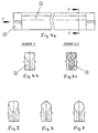
- the grate bars 2 preferably have a profile tapering downward in cross section Gap area to avoid the jamming of boundary grain. For further protection of "soft" screenings and for the head profile of the Grate bar preferably be rounded (Fig. 4, 5, 6).
- the mounting profile 9 is preferably at the end arranged at the ends of the grate bars 2.
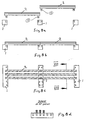
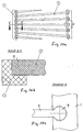
- the Mounting profiles 9 can also be centered on the grate bars 2 to be appropriate. This is the top of the Crossbar 1 and that of the grate bars 2 on one level. To increase the open screen area, the The mounting profiles on the grate bars protrude downwards (Fig. 8a). The grate bars run when assembled then over the crossbar, which is such a continuous Form a gap.
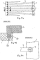
- Mounting profile 9 is angular. But as soon as one conical gap course is necessary, this is achieved through tapering training in the direction of conveyance the grate bars and / or by a widening one another Arrangement of the grate bars (Fig. 9, 10) so that the columns widen between the grate bars.
- Mounting profile preferably round, especially cylindrical (Fig. 9, 10) formed, that is, the mounting profiles are down (Fig. 9a to 9c) or face (Fig. 10a to 10c) parts protruding from the grate bars, especially cones with in particular round horizontal cross section and in particular cylindrical shape with vertical cylinder axis. In order to distribution of the screenings is achieved at the same time.
- FIG. 2a and 2b can preferably in the lower area of the grate bars on one or both sides Spacer knobs (3a and 3b) must be worked in on the side.
- the Flank slope 3-20 degrees, preferably 5-10 degrees should and the mounting profile with an oversize is to ensure a secure hold on the crossbeam to reach.
- horizontal Collar bolts 11 are provided, each half in semi-cylindrical recesses of the mounting profile 9 and the mounting recess 6 on both sides of the mounting profile insert and therefore preferably the Locking projection 8 and the locking recess 7 replace.
- Vertical drainage or cleaning openings 10 extend from the bottom of the locking recess down through the crossbar.
- the mounting profiles under the Profile bars may be arranged. As a result, the Crossbeam below the profile bars.
- the recesses and mounting profiles are subject to stress conical.
Landscapes
- Combined Means For Separation Of Solids (AREA)
Abstract
Description
Die Erfindung betrifft einen Siebrost zum Trennen von Schüttgütern mit nebeneinander angeordneten Roststäben, die zwischen sich Spalten bilden und die an Querbalken befestigt sind.The invention relates to a sieve grate for separating Bulk goods with grate bars arranged side by side, that form gaps between themselves and those on crossbars are attached.
Herkömmliche Siebroste zum groben Trennen von Schüttgütern bestehen aus Querbalken mit größeren Abständen und ein- oder aufgeschraubten bzw. ein- oder aufgeschweißten Roststäben mit kleineren Abständen. Entsprechend der Anordnung der Querbalken und der Roststäbe ergeben sich Spalten. Die Roste können eben, mit einer Neigung und/oder in Stufen angeordnet sein. Der Werkstoff dieser Roste ist aus Stahl. Sind die Roste zusammengeschraubt, so sind Montage und Demontage aufwendig. Sind sie zusammengeschweißt, so sind Montage und Demontage auch aufwendig und es können keine einzelnen Roststäbe gewechselt werden, sondern es muß der gesamte verschweißte Rahmen ausgewechselt werden. Ferner besteht die Gefahr der Rostbildung. Bei weicheren abzusiebenden / zu entwässernden Materialien (zum Beispiel Hackfrüchte wie Kartoffeln, Rüben etc.) erfolgt eine Beschädigung durch die harten Werkstoffe.Conventional sieve grids for rough separation of Bulk goods consist of crossbeams with larger ones Distances and screwed or screwed or on or welded-on grate bars with smaller distances. According to the arrangement of the crossbars and the Rust bars result in gaps. The grates can be arranged with an inclination and / or in steps. The material of these gratings is made of steel. Are the grates screwed together, so are assembly and disassembly complex. If they are welded together, there is assembly and disassembly also complex and it can not individual grate bars to be replaced, but it must the entire welded frame can be replaced. There is also a risk of rust formation. For softer ones materials to be screened / dewatered (for Example root crops such as potatoes, beets, etc.) damage from the hard materials.
Aufgabe der Erfindung ist es, bei einem Siebrost der eingangs genannten Art Herstellung, Montage, Demontage und Wartung zu vereinfachen und zu verbessern und hierbei eine hohe Betriebssicherheit zu erreichen.The object of the invention is in a sieve grid Production, assembly, disassembly and simplify and improve maintenance and to achieve high operational reliability.
Diese Aufgabe wird erfindungsgemäß dadurch erreicht, daß die Roststäbe an den Querbalken formschlüssig lösbar befestigt sind.According to the invention, this object is achieved by that the grate bars on the crossbar are positive are releasably attached.
Ein solcher Rostsieb ist besonders einfach herzustellen und vorzugsweise ohne Werkzeuge zu montieren. Insbesondere weist es eine hohe Betriebssicherheit und eine leichte Reparatur auf.Such a grate screen is particularly easy to manufacture and preferably to be assembled without tools. In particular, it has high operational reliability and an easy repair on.
Vorteilhafte Ausgestaltungen der Erfindung sind in den Unteransprüchen aufgeführt.Advantageous embodiments of the invention are in the Subclaims listed.
Ausführungsbeispiele der Erfindung sind in den Zeichnungen dargestellt und werden im folgenden näher beschrieben. Es zeigen
- Fig. 1a
- eine Seitenansicht einer ersten Ausführungsform,
- Fig. 1b
- eine Ansicht nach A-A in Fig. 1a
- Fig. 1c
- einen Ausschnitt aus Fig. 1b,
- Fig. 2a
- eine Draufsicht auf eine zweite Ausführungsform,
- Fig. 2b
- eine Ansicht nach B-B in Fig. 2a,
- Fig. 3
- Seitenansichten dreier Ausführungsformen,
- Fig. 4a
- eine Seitenansicht eines Roststabes,
- Fig. 4b
- eine Stirnansiht nach Pfeil Y in Fig. 4a,
- Fig. 4c
- einen Schnitt C-C in Fig. 4a,
- Fig. 5 bis 7
- eine Stirnansicht des Montageprofils in alternativen Formen,
- Fig. 8a
- einen Siebrost mit abgenommenen Roststäben,
- Fig. 8b
- einen Siebrost mit aufgesetzten Roststäben,
- Fig. 8c
- eine Draufsicht auf den Siebrost nach Fig. 8b,
- Fig. 8d
- einen senkrechten Schnitt nach VIII - VIII in Fig. 8c,
- Fig. 9a
- einen Siebrost mit einander sich weitenden Roststäben,
- Fig. 9b
- einen Schnitt durch den Siebrost nach D-D in Fig. 9a,
- Fig. 9c
- den Ausschnitt Z in Fig, 9a in Vergrößerung,
- Fig. 10a
- einen Siebrost mit teilzylindrischen Roststabenden,
- Fig. 10b
- einen Schnitt nach E-E in Fig. 10a,
- Fig. 10c
- den Ausschnitt W in Fig. 10a in Vergrößerung,
- Fig. 11a
- eine Seitenansicht eines Befestigungsbolzens,
- Fig. 11b
- einen senkrechten Schnitt durch einen Querbalken mit zwei Roststäben,
- Fig. 11c
- einen Schnitt nach F-F in Fig. 11a,
- Fig. 12
- einen Roststab mit Montageprofilen in einem Abstand zu den Roststabenden, wobei ein Profil nach unten vorsteht.
- Fig. 1a
- a side view of a first embodiment,
- Fig. 1b
- a view according to AA in Fig. 1a
- Fig. 1c
- a section of Fig. 1b,
- Fig. 2a
- a plan view of a second embodiment,
- Fig. 2b
- a view according to BB in Fig. 2a,
- Fig. 3
- Side views of three embodiments,
- Fig. 4a
- a side view of a grate bar,
- Fig. 4b
- a front view according to arrow Y in Fig. 4a,
- Fig. 4c
- a section CC in Fig. 4a,
- 5 to 7
- an end view of the mounting profile in alternative forms,
- Fig. 8a
- a sieve grate with the grate bars removed,
- Fig. 8b
- a sieve grate with attached grate bars,
- Fig. 8c
- a plan view of the sieve grate according to Fig. 8b,
- Fig. 8d
- a vertical section according to VIII - VIII in Fig. 8c,
- Fig. 9a
- a sieve grid with grating bars widening with each other,
- Fig. 9b
- 9 a section through the sieve grate according to DD in FIG. 9 a,
- Fig. 9c
- the section Z in Fig. 9a in enlargement,
- Fig. 10a
- a sieve grate with partially cylindrical grate bar ends,
- Fig. 10b
- 10 shows a section according to EE in FIG. 10a,
- Fig. 10c
- the section W in Fig. 10a on an enlarged scale,
- Fig. 11a
- a side view of a fastening bolt,
- Fig. 11b
- a vertical section through a crossbeam with two grate bars,
- Fig. 11c
- 11 shows a section according to FF in FIG. 11a,
- Fig. 12
- a grate bar with mounting profiles at a distance from the grate bar ends, with a profile protruding downwards.
Der Rost weist mindestens zwei Querbalken 1 und daran
lösbar befestigte Roststäbe 2 auf. Der für Querbalken
und Roststäbe verwendete Werkstoff ist gummielastisch
vorzugsweise Polyurethan 5. Die Querbalken sowie die
Roststäbe können mit Armierungen versehen sein. Die
Querbalken enthalten nach oben offene
Montageausnehmungen 6, in denen die Roststäbe 2 von
Hand von oben reingedrückt werden. Eine insbesondere
sägezahnförmige Arretierungsausnehmung 7 in der
Montageausnehmung 6 im Querbalken 1 und ein
Arretierungsvorsprung 8 gleichen Querschnitts am
Roststab 2 verhindern ein ungewolltes Lösen, das durch
die Beaufschlagungsvibration erfolgen könnte. The grate has at least two
Durch den Abstand der Montageausnehmungen 6 im
Querbalken und der Roststabbreite wird die Spaltweite
bestimmt. Die Spaltlänge wird durch den Abstand der
Querbalken bestimmt. Die Roststäbe 2 haben vorzugsweise
ein im Querschnitt sich nach unten verjüngendes Profil im
Spaltbereich, um die Klemmung von Grenzkorn zu vermeiden.
Zur weiteren Schonung von "weichem" Siebgut und zum
besseren Entwässerungseffekt kann das Kopfprofil des
Roststabes vorzugsweise abgerundet ausgebildet sein (Fig.
4, 5, 6).By the distance of the mounting
Vorzugsweise ist das Montageprofil 9 jeweils stirnseitig
an den Enden der Roststäbe 2 angeordnet. Die
Montageprofile 9 können auch mittig an den Roststäben 2
angebracht sein. Damit liegen die Oberseiten der
Querbalken 1 sowie die der Roststäbe 2 auf einer Ebene.
Um die offene Siebfläche zu vergrößern, können die
Montageprofile an den Roststäben nach unten hervorstehen
(Fig. 8a). Im montierten Zustand verlaufen die Roststäbe
dann über den Querbalken, die so einen durchgehenden
Spalt bilden.The mounting
Es ist üblich, daß der Spaltverlauf parallel ist und das
Montageprofil 9 kantig ausgeführt ist. Sobald aber ein
konischer Spaltverlauf notwendig wird, erreicht man dies
durch eine in Förderrichtung sich verjüngende Ausbildung
der Roststäbe und/oder durch eine sich einander weitende
Anordnung der Roststäbe (Fig. 9, 10), so daß die Spalten
zwischen den Roststäben sich weiten. Hierbei ist das
Montageprofil vorzugsweise rund, insbesondere zylindrisch
(Fig. 9, 10) ausgebildet, das heißt die Montageprofile
sind nach unten (Fig. 9a bis 9c) oder stirnseitig (Fig.
10a bis 10c) an den Roststäben vorstehende Teile,
insbesondere Zapfen mit insbesondere
rundem waagerechtem Querschnitt und insbesondere
zylindrischer Form mit senkrechter Zylinderachse. Damit
wird gleichzeitig ein Verteilen des Siebgutes erreicht.It is common for the gap to be parallel and that
Mounting
Zur Spaltsicherung (Fig. 2a und 2b) können vorzugsweise im unteren Bereich der Roststäbe ein- oder beidseitig Distanznoppen (3a und 3b) seitlich angearbeitet sein.To secure the gap (Fig. 2a and 2b) can preferably in the lower area of the grate bars on one or both sides Spacer knobs (3a and 3b) must be worked in on the side.
Zur dynamischen Beanspruchung eines Profil-Rostes ist vorzugsweise ein nach unten sich verjüngendes Montageprofil 9 vorzusehen (Fig. 11c), wobei die Flankenneigung 3-20 Grad, vorzugsweise 5-10 Grad sein sollte und das Montageprofil mit einem Übermaß zu fertigen ist, um einen sicheren Halt am Querbalken zu erreichen.For the dynamic loading of a profile grate preferably a tapering downward Provide mounting profile 9 (Fig. 11c), the Flank slope 3-20 degrees, preferably 5-10 degrees should and the mounting profile with an oversize is to ensure a secure hold on the crossbeam to reach.
Für eine zusätzliche Arretierung können waagerechte
Bundbolzen 11 vorgesehen sein, die je zur Hälfte in
halbzylindrischen Ausnehmungen des Montageprofils 9 und
der Montageausnehmung 6 beidseitig des Montageprofils
einliegen und damit vorzugsweise den
Arretierungsvorsprung 8 und die Arretierungsausnehmung
7 ersetzen.For an additional locking,
Senkrechte Entwässerungs- bzw. Reinigungsöffnungen 10 (Fig. 9b) verlaufen vom Boden der Arretierungsausnehmung durch den Querbalken nach unten.Vertical drainage or cleaning openings 10 (Fig. 9b) extend from the bottom of the locking recess down through the crossbar.
Für durchgängige Spalten und einer größeren offenen
Siebfläche können die Montageprofile unter den
Profilstäben angeordnet sein. Demzufolge verlaufen die
Querbalken unterhalb der Profilstäbe. Für eine dynamische
Beanspruchung sind die Ausnehmungen und Montageprofile
konisch ausgebildet. Um die Steifigkeit sowohl in der
Längs- als auch in der Querachse zu erhöhen, können die
Montageprofile 9 auch weiter zur Mitte hin am Profilstab
2 angebracht sein.For continuous gaps and a larger open one
The mounting profiles under the
Profile bars may be arranged. As a result, the
Crossbeam below the profile bars. For a dynamic
The recesses and mounting profiles are subject to stress
conical. To the rigidity both in the
To increase the longitudinal as well as in the transverse axis
Mounting profiles 9 also further towards the center on the
Claims (15)
Priority Applications (1)
| Application Number | Priority Date | Filing Date | Title |
|---|---|---|---|
| DE29924351U DE29924351U1 (en) | 1998-03-25 | 1999-02-27 | grate |
Applications Claiming Priority (2)
| Application Number | Priority Date | Filing Date | Title |
|---|---|---|---|
| DE19813006 | 1998-03-25 | ||
| DE19813006 | 1998-03-25 |
Publications (3)
| Publication Number | Publication Date |
|---|---|
| EP0945189A2 true EP0945189A2 (en) | 1999-09-29 |
| EP0945189A3 EP0945189A3 (en) | 2000-05-31 |
| EP0945189B1 EP0945189B1 (en) | 2002-07-17 |
Family
ID=7862187
Family Applications (1)
| Application Number | Title | Priority Date | Filing Date |
|---|---|---|---|
| EP99103822A Expired - Lifetime EP0945189B1 (en) | 1998-03-25 | 1999-02-27 | Sieve grate |
Country Status (2)
| Country | Link |
|---|---|
| EP (1) | EP0945189B1 (en) |
| DE (2) | DE19904091A1 (en) |
Cited By (5)
| Publication number | Priority date | Publication date | Assignee | Title |
|---|---|---|---|---|
| EP1230987A1 (en) * | 2001-02-13 | 2002-08-14 | Isenmann Siebe GmbH | Screen with slit-shaped or elongated apertures |
| WO2008150850A1 (en) * | 2007-05-29 | 2008-12-11 | Blueline Enterprises, Inc. | Material separator |
| EP1726370A3 (en) * | 2005-05-25 | 2009-06-17 | Isenmann Siebe GmbH | Rod grate screening surface |
| EP3023165A1 (en) * | 2014-11-19 | 2016-05-25 | Stocker Mechatronik GmbH | Slotted screen |
| EP3520908A3 (en) * | 2018-01-23 | 2019-09-11 | Terex GB Limited | Screening bar assembly for a screen |
Families Citing this family (2)
| Publication number | Priority date | Publication date | Assignee | Title |
|---|---|---|---|---|
| FR2815548B1 (en) * | 2000-10-25 | 2003-08-15 | Technos Et Cie | SEPARATION GRID FOR SEPARATING CLEANING BODIES FROM A FLUID AND DEVICE COMPRISING SUCH A GRID |
| DE102007008447A1 (en) * | 2007-02-19 | 2008-04-17 | Tegel Technik Gmbh | Vibrating body e.g. shaker body, for sorting device i.e. ballistics separator, has longitudinal sections running in direction of longitudinal axis, alternatively inserted or brought by openings of cross bars and held in detachable manner |
Family Cites Families (4)
| Publication number | Priority date | Publication date | Assignee | Title |
|---|---|---|---|---|
| DE1126331B (en) * | 1961-04-19 | 1962-03-22 | Hewitt Robins Internat S A | Vibrating sieve |
| US3901801A (en) * | 1974-06-17 | 1975-08-26 | Hendrick Mfg Co | Industrial screen |
| US4381235A (en) * | 1980-11-20 | 1983-04-26 | Powerscreen Limited | Screening apparatus |
| SE443302B (en) * | 1980-11-24 | 1986-02-24 | Berglunds Mek Ab | SHAKT MASSOR SORTING DEVICE |
-
1999
- 1999-02-02 DE DE19904091A patent/DE19904091A1/en not_active Withdrawn
- 1999-02-27 EP EP99103822A patent/EP0945189B1/en not_active Expired - Lifetime
- 1999-02-27 DE DE59902011T patent/DE59902011D1/en not_active Expired - Fee Related
Cited By (7)
| Publication number | Priority date | Publication date | Assignee | Title |
|---|---|---|---|---|
| EP1230987A1 (en) * | 2001-02-13 | 2002-08-14 | Isenmann Siebe GmbH | Screen with slit-shaped or elongated apertures |
| DE10106499A1 (en) * | 2001-02-13 | 2002-08-29 | Isenmann Siebe Gmbh | Sieve with slit or slit-shaped sieve openings |
| EP1726370A3 (en) * | 2005-05-25 | 2009-06-17 | Isenmann Siebe GmbH | Rod grate screening surface |
| WO2008150850A1 (en) * | 2007-05-29 | 2008-12-11 | Blueline Enterprises, Inc. | Material separator |
| EP3023165A1 (en) * | 2014-11-19 | 2016-05-25 | Stocker Mechatronik GmbH | Slotted screen |
| EP3520908A3 (en) * | 2018-01-23 | 2019-09-11 | Terex GB Limited | Screening bar assembly for a screen |
| US11198156B2 (en) | 2018-01-23 | 2021-12-14 | Terex Gb Limited | Screening bar assembly for a screen |
Also Published As
| Publication number | Publication date |
|---|---|
| DE59902011D1 (en) | 2002-08-22 |
| EP0945189B1 (en) | 2002-07-17 |
| DE19904091A1 (en) | 1999-09-30 |
| EP0945189A3 (en) | 2000-05-31 |
Similar Documents
| Publication | Publication Date | Title |
|---|---|---|
| DE3390381C2 (en) | Screening device comprising a plurality of screen elements | |
| DE3827259A1 (en) | SCREEN ARRANGEMENT | |
| WO1981002398A1 (en) | Self cleaning,perforated plate for oscillating sieve | |
| DE3114574A1 (en) | VIBRATION SCREEN WITH A DEVICE FOR REMOVING THE CLOGGING OF THE SCREEN | |
| DE1295579B (en) | Device for bridging expansion joints, especially in bridges | |
| DE4303892C2 (en) | Screen covering | |
| DE3301493C2 (en) | ||
| EP0945189B1 (en) | Sieve grate | |
| EP1544377B1 (en) | Form for curved wall | |
| DE2832747B1 (en) | Screen deck | |
| DE3914907C2 (en) | Raised floor plate | |
| EP4101977A1 (en) | Wiping strip and kit for use in an installation for producing a paper sheet | |
| DE2634934B2 (en) | Plate-like sieve element | |
| DE3307677A1 (en) | Separating drum, in particular for separating centrifuges | |
| CH627379A5 (en) | Screen | |
| DE2706277C3 (en) | Sieve bottom | |
| DE29924351U1 (en) | grate | |
| DE8904477U1 (en) | Sieve bottom | |
| DE1156723B (en) | Screen grate | |
| DE602004011125T2 (en) | STRUCTURAL ARRANGEMENT FOR SWING FACILITIES | |
| DE1162782B (en) | Screen grate | |
| EP0641608A2 (en) | Screening machine | |
| DE3304679C1 (en) | Screen lining with screen trays arranged one on top of the other | |
| DE19844015B4 (en) | Transport box made in one piece from plastic | |
| EP0736336B1 (en) | Screening machine |
Legal Events
| Date | Code | Title | Description |
|---|---|---|---|
| PUAI | Public reference made under article 153(3) epc to a published international application that has entered the european phase |
Free format text: ORIGINAL CODE: 0009012 |
|
| AK | Designated contracting states |
Kind code of ref document: A2 Designated state(s): BE DE DK ES FR GB IT NL |
|
| AX | Request for extension of the european patent |
Free format text: AL;LT;LV;MK;RO PAYMENT 19990227;SI PAYMENT 19990227 |
|
| PUAL | Search report despatched |
Free format text: ORIGINAL CODE: 0009013 |
|
| AK | Designated contracting states |
Kind code of ref document: A3 Designated state(s): AT BE CH CY DE DK ES FI FR GB GR IE IT LI LU MC NL PT SE |
|
| AX | Request for extension of the european patent |
Free format text: AL;LT;LV;MK;RO PAYMENT 19990227;SI PAYMENT 19990227 |
|
| AKX | Designation fees paid |
Free format text: BE DE DK ES FR GB IT NL |
|
| AXX | Extension fees paid |
Free format text: RO PAYMENT 19990227;SI PAYMENT 19990227 |
|
| 17P | Request for examination filed |
Effective date: 20001018 |
|
| GRAG | Despatch of communication of intention to grant |
Free format text: ORIGINAL CODE: EPIDOS AGRA |
|
| 17Q | First examination report despatched |
Effective date: 20011129 |
|
| GRAG | Despatch of communication of intention to grant |
Free format text: ORIGINAL CODE: EPIDOS AGRA |
|
| GRAH | Despatch of communication of intention to grant a patent |
Free format text: ORIGINAL CODE: EPIDOS IGRA |
|
| GRAH | Despatch of communication of intention to grant a patent |
Free format text: ORIGINAL CODE: EPIDOS IGRA |
|
| GRAA | (expected) grant |
Free format text: ORIGINAL CODE: 0009210 |
|
| AK | Designated contracting states |
Kind code of ref document: B1 Designated state(s): BE DE DK ES FR GB IT NL |
|
| AX | Request for extension of the european patent |
Free format text: RO PAYMENT 19990227;SI PAYMENT 19990227 |
|
| PG25 | Lapsed in a contracting state [announced via postgrant information from national office to epo] |
Ref country code: IT Free format text: LAPSE BECAUSE OF FAILURE TO SUBMIT A TRANSLATION OF THE DESCRIPTION OR TO PAY THE FEE WITHIN THE PRESCRIBED TIME-LIMIT;WARNING: LAPSES OF ITALIAN PATENTS WITH EFFECTIVE DATE BEFORE 2007 MAY HAVE OCCURRED AT ANY TIME BEFORE 2007. THE CORRECT EFFECTIVE DATE MAY BE DIFFERENT FROM THE ONE RECORDED. Effective date: 20020717 |
|
| REG | Reference to a national code |
Ref country code: GB Ref legal event code: FG4D Free format text: NOT ENGLISH |
|
| REF | Corresponds to: |
Ref document number: 59902011 Country of ref document: DE Date of ref document: 20020822 |
|
| GBT | Gb: translation of ep patent filed (gb section 77(6)(a)/1977) |
Effective date: 20020813 |
|
| PG25 | Lapsed in a contracting state [announced via postgrant information from national office to epo] |
Ref country code: DK Free format text: LAPSE BECAUSE OF FAILURE TO SUBMIT A TRANSLATION OF THE DESCRIPTION OR TO PAY THE FEE WITHIN THE PRESCRIBED TIME-LIMIT Effective date: 20021017 |
|
| ET | Fr: translation filed | ||
| PG25 | Lapsed in a contracting state [announced via postgrant information from national office to epo] |
Ref country code: ES Free format text: LAPSE BECAUSE OF FAILURE TO SUBMIT A TRANSLATION OF THE DESCRIPTION OR TO PAY THE FEE WITHIN THE PRESCRIBED TIME-LIMIT Effective date: 20030130 |
|
| PLBI | Opposition filed |
Free format text: ORIGINAL CODE: 0009260 |
|
| PLBQ | Unpublished change to opponent data |
Free format text: ORIGINAL CODE: EPIDOS OPPO |
|
| PLBF | Reply of patent proprietor to notice(s) of opposition |
Free format text: ORIGINAL CODE: EPIDOS OBSO |
|
| 26 | Opposition filed |
Opponent name: GUMMI KUEPER GMBH & CO KG Effective date: 20030417 |
|
| NLR1 | Nl: opposition has been filed with the epo |
Opponent name: GUMMI KUEPER GMBH & CO KG |
|
| PLAX | Notice of opposition and request to file observation + time limit sent |
Free format text: ORIGINAL CODE: EPIDOSNOBS2 |
|
| PLBB | Reply of patent proprietor to notice(s) of opposition received |
Free format text: ORIGINAL CODE: EPIDOSNOBS3 |
|
| PLCK | Communication despatched that opposition was rejected |
Free format text: ORIGINAL CODE: EPIDOSNREJ1 |
|
| PLBN | Opposition rejected |
Free format text: ORIGINAL CODE: 0009273 |
|
| STAA | Information on the status of an ep patent application or granted ep patent |
Free format text: STATUS: OPPOSITION REJECTED |
|
| 27O | Opposition rejected |
Effective date: 20040619 |
|
| NLR2 | Nl: decision of opposition |
Effective date: 20040619 |
|
| PGFP | Annual fee paid to national office [announced via postgrant information from national office to epo] |
Ref country code: NL Payment date: 20050203 Year of fee payment: 7 |
|
| PGFP | Annual fee paid to national office [announced via postgrant information from national office to epo] |
Ref country code: FR Payment date: 20050208 Year of fee payment: 7 |
|
| PGFP | Annual fee paid to national office [announced via postgrant information from national office to epo] |
Ref country code: GB Payment date: 20050223 Year of fee payment: 7 |
|
| PGFP | Annual fee paid to national office [announced via postgrant information from national office to epo] |
Ref country code: DE Payment date: 20050224 Year of fee payment: 7 |
|
| PGFP | Annual fee paid to national office [announced via postgrant information from national office to epo] |
Ref country code: BE Payment date: 20050408 Year of fee payment: 7 |
|
| PG25 | Lapsed in a contracting state [announced via postgrant information from national office to epo] |
Ref country code: GB Free format text: LAPSE BECAUSE OF NON-PAYMENT OF DUE FEES Effective date: 20060227 |
|
| PG25 | Lapsed in a contracting state [announced via postgrant information from national office to epo] |
Ref country code: BE Free format text: LAPSE BECAUSE OF NON-PAYMENT OF DUE FEES Effective date: 20060228 |
|
| PG25 | Lapsed in a contracting state [announced via postgrant information from national office to epo] |
Ref country code: NL Free format text: LAPSE BECAUSE OF NON-PAYMENT OF DUE FEES Effective date: 20060901 Ref country code: DE Free format text: LAPSE BECAUSE OF NON-PAYMENT OF DUE FEES Effective date: 20060901 |
|
| GBPC | Gb: european patent ceased through non-payment of renewal fee |
Effective date: 20060227 |
|
| NLV4 | Nl: lapsed or anulled due to non-payment of the annual fee |
Effective date: 20060901 |
|
| REG | Reference to a national code |
Ref country code: FR Ref legal event code: ST Effective date: 20061031 |
|
| BERE | Be: lapsed |
Owner name: *ISENMANN SIEBE G.M.B.H. Effective date: 20060228 |
|
| PG25 | Lapsed in a contracting state [announced via postgrant information from national office to epo] |
Ref country code: FR Free format text: LAPSE BECAUSE OF NON-PAYMENT OF DUE FEES Effective date: 20060228 |