EP0944544B2 - Method and device for conveying individually held products - Google Patents
Method and device for conveying individually held products Download PDFInfo
- Publication number
- EP0944544B2 EP0944544B2 EP97913069A EP97913069A EP0944544B2 EP 0944544 B2 EP0944544 B2 EP 0944544B2 EP 97913069 A EP97913069 A EP 97913069A EP 97913069 A EP97913069 A EP 97913069A EP 0944544 B2 EP0944544 B2 EP 0944544B2
- Authority
- EP
- European Patent Office
- Prior art keywords
- conveying
- elements
- path
- paths
- holding
- Prior art date
- Legal status (The legal status is an assumption and is not a legal conclusion. Google has not performed a legal analysis and makes no representation as to the accuracy of the status listed.)
- Expired - Lifetime
Links
- 238000000034 method Methods 0.000 title claims description 53
- 230000008878 coupling Effects 0.000 claims abstract description 148
- 238000010168 coupling process Methods 0.000 claims abstract description 148
- 238000005859 coupling reaction Methods 0.000 claims abstract description 148
- 210000001520 comb Anatomy 0.000 claims description 6
- 238000005096 rolling process Methods 0.000 claims description 2
- 239000000047 product Substances 0.000 description 54
- 230000008569 process Effects 0.000 description 8
- 230000001360 synchronised effect Effects 0.000 description 5
- 238000003032 molecular docking Methods 0.000 description 4
- 230000008901 benefit Effects 0.000 description 3
- 230000005484 gravity Effects 0.000 description 3
- 230000001737 promoting effect Effects 0.000 description 3
- 230000004913 activation Effects 0.000 description 2
- 239000003795 chemical substances by application Substances 0.000 description 2
- 230000009849 deactivation Effects 0.000 description 2
- 235000004522 Pentaglottis sempervirens Nutrition 0.000 description 1
- 230000003213 activating effect Effects 0.000 description 1
- 238000005516 engineering process Methods 0.000 description 1
- 239000013067 intermediate product Substances 0.000 description 1
- 239000000696 magnetic material Substances 0.000 description 1
- 238000007726 management method Methods 0.000 description 1
- 238000004519 manufacturing process Methods 0.000 description 1
- 238000007639 printing Methods 0.000 description 1
Images


Classifications
-
- B—PERFORMING OPERATIONS; TRANSPORTING
- B65—CONVEYING; PACKING; STORING; HANDLING THIN OR FILAMENTARY MATERIAL
- B65H—HANDLING THIN OR FILAMENTARY MATERIAL, e.g. SHEETS, WEBS, CABLES
- B65H29/00—Delivering or advancing articles from machines; Advancing articles to or into piles
- B65H29/58—Article switches or diverters
- B65H29/60—Article switches or diverters diverting the stream into alternative paths
-
- B—PERFORMING OPERATIONS; TRANSPORTING
- B65—CONVEYING; PACKING; STORING; HANDLING THIN OR FILAMENTARY MATERIAL
- B65H—HANDLING THIN OR FILAMENTARY MATERIAL, e.g. SHEETS, WEBS, CABLES
- B65H29/00—Delivering or advancing articles from machines; Advancing articles to or into piles
- B65H29/003—Delivering or advancing articles from machines; Advancing articles to or into piles by grippers
-
- B—PERFORMING OPERATIONS; TRANSPORTING
- B65—CONVEYING; PACKING; STORING; HANDLING THIN OR FILAMENTARY MATERIAL
- B65H—HANDLING THIN OR FILAMENTARY MATERIAL, e.g. SHEETS, WEBS, CABLES
- B65H2301/00—Handling processes for sheets or webs
- B65H2301/30—Orientation, displacement, position of the handled material
- B65H2301/32—Orientation of handled material
- B65H2301/323—Hanging
-
- B—PERFORMING OPERATIONS; TRANSPORTING
- B65—CONVEYING; PACKING; STORING; HANDLING THIN OR FILAMENTARY MATERIAL
- B65H—HANDLING THIN OR FILAMENTARY MATERIAL, e.g. SHEETS, WEBS, CABLES
- B65H2301/00—Handling processes for sheets or webs
- B65H2301/40—Type of handling process
- B65H2301/44—Moving, forwarding, guiding material
- B65H2301/447—Moving, forwarding, guiding material transferring material between transport devices
- B65H2301/4471—Grippers, e.g. moved in paths enclosing an area
-
- B—PERFORMING OPERATIONS; TRANSPORTING
- B65—CONVEYING; PACKING; STORING; HANDLING THIN OR FILAMENTARY MATERIAL
- B65H—HANDLING THIN OR FILAMENTARY MATERIAL, e.g. SHEETS, WEBS, CABLES
- B65H2405/00—Parts for holding the handled material
- B65H2405/50—Gripping means
- B65H2405/56—Gripping means releasably connected to transporting means
Definitions
- the invention is in the field of conveyor technology and relates to a method for conveying individually held products according to the preamble of the first independent claim, and an arrangement for Implementation of the method according to the preamble of the corresponding independent claim.
- the products to be considered below are considered to be individual and may be individual Because of essentially continuously conveyed through a network of conveyor lines. Through this promotion will be For example, the products are taken from a manufacturing process to stations where they are processed individually be transferred from one processing station to another processing station or through processing stations, in which they are processed during continuous support.
- An example for products to be handled in this way are printed products which, starting from the printing press, are replaced by a wide variety of different types Processing stations are further processed and made ready for shipment.
- the arrangements for conveying piece goods described above are particularly suitable for product streams, which are conveyed with substantially unchanged product sequence over longer conveyor lines.
- the Arrangements are robust and easy to operate even at very high flow rates and the return of the holding means is realizable without specific control on a simple backward run.
- the invention is now the task of a method for promoting individually held products show that combines the advantages of the systems described above, but largely eliminates their disadvantages.
- the method should be largely independent of variations in form with respect to the promotional Products, it should also be applicable for very high flow rates and it should be better than known such Procedures in various areas, through which the products are to be promoted, to a variety of conveying tasks be customizable. Furthermore, it is the object of the invention to provide an arrangement for carrying out the method create which arrangement can be easily adapted to a variety of local transport tasks and also easily expandable is.
- the method according to the invention is based on assigning a holding element to each product to be conveyed, which holding element holds the product in a defined manner and which holding element together with the product travels the entire predetermined for the product conveying path, which conveyor from a series consists of conveyor lines.
- the holding elements are coupled to the conveyor for parts that are along a specific conveyor line are movable, or on guides that extend along a specific conveyor line.
- the holding elements each have at least one first coupling part, with the aid of which they are connected to second coupling parts can be coupled, each second coupling part assigned to a specific conveyor line substantially and is movable along this.
- the holding elements with Help the first coupling parts and on guides that extend along a conveyor line, coupled become.
- a product to be conveyed is held by a holding element and the holding element is by means of the first coupling part to a movable along the conveying path second Coupling part or coupled to a along the conveying path extending guide, wherein the coupling part or, a conveying element on which it is arranged, or the holding element is driven by suitable means.
- the holding element In Transfer areas, ie in places where the product from one conveyor line to another conveyor line is guided, the holding element, from the movable on the one conveyor line second coupling part or corresponding guide decoupled and to a movable on the other conveyor section second coupling part or coupled to a corresponding leadership, this transfer can affect all products of a stream or only individual.
- the advantage of the method is, on the one hand, that the products to be conveyed are taken only once which significantly reduces the risk of damage and makes the process largely independent will depend on the exact shape of the products.
- the movable on conveyor lines second coupling parts can, for example, in equidistant manner Be arranged conveyor chains. If holding elements are coupled to such a conveyor chain, it corresponds in their function of a known conveyor chain, as described above.
- the second coupling parts can also be arranged on links of chains with variable link distances or they can be completely independent be arranged from each other movable conveyor elements. Depending on the way the second coupling parts along a certain conveyor line are movable, and appropriate drive means are interpreted and arranged.
- conveyor lines with second coupling parts movable thereon in addition to the conveyor lines with second coupling parts movable thereon, in an inventive Arrangement also be provided conveyor lines on which the holding elements without coupling movable are, for example, the fact that their first coupling parts slide in appropriately designed guides, for example, powered by gravity. Such additional conveyor lines are particularly suitable for a non-continuous promotion, so for example for buffer lines and for return routes.
- Another advantage of the inventive method and the inventive arrangement is in that in processes in which it is advantageous to individually identify the products, the means of identification not on the products themselves but on the holding elements can be arranged and thereby the conveyor system Do not leave with the products, but with the circulating in the holding elements in the system.
- Denieri Mittelzur Identification are, for example, contactlessly writable and readable electronic units.
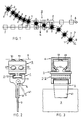
- FIG. 1 schematically shows a first exemplary variant of the method according to the invention with reference to a very limited network with only two conveyor lines A and B in a transfer area U and its immediate surroundings.
- the two conveyor lines are shown schematically by lines with arrow (conveying direction).
- second coupling parts 2 are movable, which are shown schematically as white squares.
- first coupling parts 1 are shown schematically as black circles.
- a holding element which holding element holds a product 3.
- the product (seen from the back in FIG. 1) is, for example, a printed product, ie a newspaper, a magazine or a brochure or an intermediate product for one of the products mentioned.
- FIG. 1 can be understood, for example, as a bird's eye view, that is to say the conveying paths A and B, coupling parts 1 and 2 and the holding elements are above the suspended conveyed products 3rd arranged.
- the representation can just as well be understood as a side view, that is, the products 3 are held laterally, the conveyor line A comes from above and the conveyor line B goes down. Also Mixed forms are readily conceivable.
- the second coupling parts 2 with constant distances from each other for example moved on articulated chain links arranged moves.
- the second coupling parts 2 no constant distances from each other, that is, they are for example loose interconnected conveyor elements or arranged on individual conveyor elements.
- the transfer area U synchronization means (not shown), with the help of the second Coupling 2 on the conveyor line A at least in the transfer area U with the second coupling parts 2 on the conveyor line B synchronized or clocked into the transfer area.
- the holding elements with the first coupling parts 1 are on the supply side (in the figure on the left) to Transfer area U coupled to the movable on the conveyor section A second coupling parts 2.
- On the conveying side (in the figure on the right) of the transfer area U are the holding elements or first coupling parts 1 are coupled to second coupling parts 2 on the conveyor line B and are on this further promoted.
- the transfer area U are in addition to synchronization means for the synchronization of the second coupling parts 2 of the two conveyor lines A and B to provide means by which the movement of the holding elements or the first coupling parts 1 transversely to the conveying direction (arrow Q) are moved, for example, correspondingatsungskulissen, as indicated by the dot-dash lines a and b.
- the Means for the transverse movement designed to be controlled accordingly. In appropriate arrangements can as Means for transverse movement also be exploited gravity.
- locking means are also provided, with the help of which two are coupled together Clutch parts 1 and 2 are locked together.
- Clutch parts 1 and 2 are locked together.
- FIGs 2 and 3 show an exemplary embodiment of a holding element 4 with a first coupling part 1 and a conveying element 5, which in a guide 6 (defined conveying path) is movable and on which a second coupling part 2 is arranged.
- Holding element 4 and conveying element 5 are shown in FIG. 2 with a viewing direction transverse to the conveying direction, in FIG. 3 with a viewing direction parallel to the conveying direction.
- FIG. 2 and 3 equipped holding elements 4 and conveying elements 5 are applicable in a process variant according to Figure 1.
- the pair shown in Figures 2 and 3 of mutually cooperating coupling parts (1/2) consists from a part with an outwardly narrowing groove 11 and a comb 12 with a narrowed neck area 13, wherein groove 11 and comb 12 have matched cross sections and at least in a transfer area extend substantially transversely to the conveying direction, such that the comb 12 transversely to the conveying direction can be pushed out of the groove 11.
- the holding element 4 has, for example, a gripper 41, with which a printed product 3 gripped and is held.
- grippers are well known, for example by the publication CH-569197 and US-3948551 (F62).
- the conveyor element 5 has, for example, two groups of three balls 51, with the help of it in a corresponding guide channel 61 is movable in rolling.
- Such conveying elements 5 are in the publication EP-0387318 and US-5074678 described.
- two guide channels 61 are guided parallel to each other and become the conveying elements 5 synchronized such that always a pair of conveying elements with aligned combs 12 promoted by the transfer area.
- the distance between the guide channels 61 is in the transfer area chosen such that the distance between two moving synchronously through the transfer area Combing 12 of two synchronously moving conveyor elements 5 is smaller than the length of a groove 11 of a Hatleetementes 4.
- the holding element 4 from the comb 12 of a conveyor element 5 slidable on the comb 12 of the other conveying element 5 these means all through the transfer area subsidized holding element can push or are controlled so that they only specific the Slide holding means.
- These means are for examplesecuritysungskulissen or magnet systems, in particular are suitable as controllable funds. .
- FIG. 4 shows another embodiment of holding elements 4 and conveying elements 5, which can be coupled to one another by a pair of coupling parts (FIGS. 1 and 2) as a representation of a further transfer region through which three conveying paths A, B and C lead (view parallel to the conveying direction).
- the holding element 4 in turn has a gripper 41, which holds a product 3 and which can be activated or deactivated to grasp a product or to release it by means of control rollers 42.
- the conveying element 5 is a link of a link chain which is movable on rollers 52 in a guide channel 61.
- the groove 11 On the holding element 4 is a comb 12 as the first coupling part 1, on the conveying element 5 as a second coupling part 2 a groove 11 arranged (coupling parts with respect to the embodiment according to Figures 2 and 3 reversed).
- the groove 11 consists of a pipe segment and the Head portion of the comb 12 of a tube whose outer diameter to the inner diameter of the pipe segment is tuned.
- the holding element 4 further comprises control rollers 43 which are for pushing the comb 12 of the groove 11 of a Conveying element 5 in the groove of another conveyor element on corresponding scenes (not shown) roll.
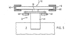
- FIG. 5 shows how a holding element 4 can be moved along an additional conveying path G, which additional conveying path has no second coupling parts.
- the retaining element 4 substantially corresponds to the retaining element of Figure 4 and is equipped with control rollers 43 and a comb 12 as the first coupling part 1.
- the comb 12, which serves for coupling to a second coupling part, has a neck region 13 which extends only over a central part of the comb length, so that the lateral regions of the comb 12 are free tube ends. With these free tube ends, the holding element 4 can slide on both sides in corresponding, for example, U-shaped guide rails 62, which can represent a further conveying variant for a specific area (eg buffer path) of an inventive conveyor arrangement.
- a return path for empty holding elements can be realized in such a manner, wherein the holding elements are advantageously driven by gravity or by other, for example, pushing drive means.
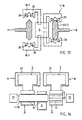
- FIG. 6 schematically shows a further transfer region U with two conveying paths A and B.
- retaining elements of which only the first coupling parts in the form of combs 12 are shown, are provided in corresponding grooves 11 of conveying elements 5.1 of the conveying path A in grooves 11 of FIG Sliding elements 5.2 of the conveying path B, wherein the grooves 11 and combs 12 extend at least in the transfer area U substantially transverse to the conveying direction.
- the conveying elements 5.1 which are movable on the conveying path A, are connected to one another in a chain, such that their distances are invariable.
- the conveying elements 5.2 are free, that is not with each other connected elements.
- the conveying elements 5.1 and 5.2 are designed for automatic synchronization.
- the Chain of the conveying elements 5.1 has for this purpose between the conveying elements concave docking sites 53, in the convex Docking 54 of the conveyor elements 5.2 fit.
- the free conveying elements 5.2 are now so against the chain led by conveying elements 5.1 that ever a convex docking 54 of a free conveyor element 5.2 in a concave docking point 53 between two connected conveying elements 5.1 is docked in a kind of positive locking.
- the free conveyor elements 5.2 are docked via the connected and driven conveyor elements 5.1 promoted at least over the transfer area U, while retaining elements, for example, from the connected 5.1 conveying elements are pushed onto the free conveying elements 52, as shown in the figure 6.
- FIG. 8 shows a further variant of a transfer area, which is operated essentially according to the same method variant as the transfer area of FIG. 1.
- two conveyor lines A and B are shown, on which second coupling parts 2 (white squares) are movable.
- a plurality of transverse conveyor elements 7 are arranged, which are synchronized with the conveying elements of the conveyor lines A and B along a third conveyor line D movable.
- a first transfer U.1 the holding elements (only first coupling parts 1 shown as black circles) with the products 3 each passed to a cross conveyor element 7 by the first coupling part 1 of the holding element from the coupling part 2 of the conveyor line A decoupled and on the cross conveyor element is pushed.
- the transverse conveying element 7 differs from the conveying element in that, instead of a second coupling part 2, it has a guide on which the first coupling part 1 of the holding element is displaceable essentially transversely to the general conveying direction.
- a control link (shown schematically are provided by the dot-dash line a), which control block also the two handovers U.1 and U.2 can control.
- the cross conveyor elements 7 for the transverse promotion of the holding elements are specially equipped with appropriate drive means.
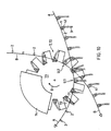
- FIG. 9 shows a three-dimensional representation of the same transfer area as FIG. 8. Only first coupling parts 1, second coupling parts 2 of the conveying paths A and B and a transverse guide 71 of a transverse conveying element are shown.
- the coupling parts 1 and 2 correspond to the coupling parts shown in Figures 2 and 3.
- the transverse guide 71 of the transverse conveyor element is essentially a comb 12 with a narrowed neck portion 13 having the same cross-section as the comb 12, the second coupling part 2, but it is usually longer than this.
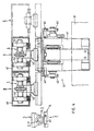
- FIG. 10 schematically shows an application of the transfer region with transverse conveying, as has already been described in connection with FIGS. 8 and 9.
- the cross conveyor elements 7 are in this case axially extending compartments 72 of a processing drum 73.
- the product-conveying conveyor line A, the drum 73 and the products weganinde conveyor line B are arranged vertically staggered one behind the other to the paper plane of Figure 10, such that the transverse conveying substantially runs perpendicular to the plane of the paper and the first transfer U.1 in a front axial region of the drum 73, the second transfer U.2 is performed in a rear axial portion of the drum.
- the products 3 are held by grippers 41 by means of first coupling parts 1 to second coupling parts 2 coupled fed along the conveyor line A.
- first coupling parts 1 are decoupled from the second coupling parts 2 and the products together Retaining elements (gripper 41 and first coupling part 1) pushed into a respective compartment 72 of the drum 73, or each first Clutch member 1 is slid onto a transverse guide 71 provided on the bottom of each compartment 72.
- the drum rotates (arrow D)
- the holding elements for example, further along the transverse guides 71 in the axial Moved towards the drum 73 and the products 3, for example, by a processing station 74th promoted and edited in it.
- second transfer U.2 on the other end of the drum 73, the processed products held by the grippers 41 by means of the first coupling parts 1 on second coupling parts coupled to the conveyor line B and conveyed away.
- FIG. 11 shows a further exemplary variant of the method according to the invention on the basis of a transfer area U, through which two conveyor lines A and B are guided.
- This variant of the method differs from the method variant according to FIGS. 1 and 8 in that the holding elements 4 each have at least two first coupling parts 1, being coupled to a second coupling part for delivery with one of the first coupling parts.
- the transverse movement Q of the holding elements 4 during transfer is unnecessary with such a variant of the method.
- FIG. 12 shows, viewed in the direction parallel to the conveying direction, a transfer region in which holding elements 4 with products 3 can be transferred from a conveying path A to a conveying path B (or vice versa) according to the second variant of the method (FIG. 11).
- the first coupling parts 1, of which each holding element 4 has two, have the form of connecting pieces 14, which are arranged aligned in opposite directions on the holding element 4.
- the on along the originallystrekken movable conveyor elements 5 arranged second coupling parts 2 are coupling gripper 15, the Gripping nozzles 14 are designed.
- the coupling gripper 15 can be activated or deactivated are.
- the person skilled in grippers and control means for their activation or deactivation are known from Conveyor systems according to the prior art, with which grippers products are taken and held. such Grippers have to be adapted accordingly for a function as second coupling parts 2 (coupling gripper).
- nozzle 14 and grippers 15 can as the first coupling parts 1 and second coupling parts 2 in the process variant according to Figure 11 a variety of known coupling parts are used, which in one Transfer area are controlled accordingly.
- FIG. 13 shows a further variant of first and second coupling parts for the process variant according to FIG. 11.
- a transfer region with two conveying sections A and B is shown (viewing direction parallel to the conveying direction), which defines conveying paths through a respective guide 63 extending along the conveying path are.
- the first coupling parts 1 of the holding elements 4 are designed as runners, which can be coupled to the guide rail and slide or roll on it.
- the guide 63 thus not only defines the conveying path but is simultaneously a second coupling part 2 for each support element 4 to be conveyed along the conveying path, wherein at each location of the conveying path a different area of the guide serves as a second coupling part and thereby the coupling can be moved along the conveying path ,
- Each holding element 4 has two first coupling parts 1 in the form of couplers which can be coupled to the guide 63 16 on.
- the runners 16 consist of two rotor parts 16.1 and 16.2, with suitable control means and optionally with return means in a closed state around the guide 63 and in a open state can be brought.
- the travelers 16 roll on rollers 20 on the guide 63 or they glide on her.
- Embodiments are also conceivable in which the guide 63 is simultaneously drive means, i. along the conveying path is moved, and the first coupling parts 1 not as a rotor but as clamping parts are, with the help of the retaining elements 4 are clamped to the guide.
- FIG. 14 again shows a third variant of the method according to the invention on the basis of a representation of a transfer area.
- two conveyor lines A and B with guide channels 61, wherein in the guide channels 61, as shown in more detail in Figure 4, conveying elements 5 are movable.
- Second coupling parts 2, which have an opening 17 oriented transversely to the conveying direction, are arranged on the conveying elements.
- the holding element 4 has a continuous same opening 17.
- the first coupling part 1 is a bolt 18 which has a cross-section matched to the openings 17 and which is displaceable transversely to the conveying direction (arrow Q) in these openings.
- the holding element is coupled to a conveying element 5 which is movable on the conveying path A or to a conveying element 5 which is movable on the conveying path B.
- openings 17 could also correspondingly extending, outwardly narrowing grooves be provided.
- drive means for the transverse movement Q of the bolt 18 in this case at least partially a magnetic material, for example, according to controllable electromagnet 19 for Application come.
- the method variant according to FIG. 14, in which a first coupling part which can be displaced transversely to the conveying direction is used, is a variant that lies between the variants according to Figures 1 and 11 according to FIG.
- the retaining element 4 has only a first coupling part 1 or bolt 18 (variant of Figure 1), but that is Retaining element 4 is not transversely displaced to the conveying direction during the transfer (variant Figure 11).
Landscapes
- Engineering & Computer Science (AREA)
- Mechanical Engineering (AREA)
- Specific Conveyance Elements (AREA)
- Discharge By Other Means (AREA)
- Supplying Of Containers To The Packaging Station (AREA)
- Intermediate Stations On Conveyors (AREA)
- Separation, Sorting, Adjustment, Or Bending Of Sheets To Be Conveyed (AREA)
- Lining Or Joining Of Plastics Or The Like (AREA)
- Branching, Merging, And Special Transfer Between Conveyors (AREA)
- Slide Fasteners (AREA)
- Lining And Supports For Tunnels (AREA)
Abstract
Description
Die Erfindung liegt auf dem Gebiete der Fördertechnik und betrifft ein Verfahren zum Fördern von individuell gehaltenen Produkten nach dem Oberbegriff des ersten unabhängigen Patentanspruchs, sowie eine Anordnung zur Durchführung des Verfahrens nach dem Oberbegriff des entsprechenden unabhängigen Patentanspruchs.The invention is in the field of conveyor technology and relates to a method for conveying individually held products according to the preamble of the first independent claim, and an arrangement for Implementation of the method according to the preamble of the corresponding independent claim.
Die im folgenden zu betrachtenden Produkte werden individuell gehalten auf gegebenenfalls individuellen Wegen im wesentlichen kontinuierlich durch ein Netz von Förderstrecken gefördert. Durch diese Förderung werden die Produkte beispielsweise aus einem Herstellungsprozess zu Stationen gebracht, in denen sie individuell bearbeitet werden, oder sie werden von einer Bearbeitungsstation zu einer weiteren Bearbeitungsstation oder durch Bearbeitungsstationen, in denen sie während der kontinuierlichen Förderung bearbeitet werden, gefördert. Ein Beispiel für derartig zu handhabende Produkte sind Druckprodukte, die von der Druckmaschine ausgehend durch verschiedenste Bearbeitungsstationen weiterverarbeitet und versandbereit gemacht werden.The products to be considered below are considered to be individual and may be individual Because of essentially continuously conveyed through a network of conveyor lines. Through this promotion will be For example, the products are taken from a manufacturing process to stations where they are processed individually be transferred from one processing station to another processing station or through processing stations, in which they are processed during continuous support. An example for products to be handled in this way are printed products which, starting from the printing press, are replaced by a wide variety of different types Processing stations are further processed and made ready for shipment.
Es ist bekannt, Druckprodukte individuell zu fördern, indem jedes der Produkte von einem Greifer oder einem anderen geeigneten Haltemittel gehalten wird. Zu diesem Zwecke wird beispielsweise eine Vielzahl von Greifern oder Haltemitteln an einer Zugkette befestigt und die Zugkette wird derart angetrieben und geführt, dass die von den Greifern oder Haltemitteln gehaltenen Produkte in einer vorbestimmten Art über eine vorbestimmte Förderstrecke gefördert werden. An Stellen, an denen alle oder einzelne Produkte eines derartigen Förderstromes von einer ersten auf eine zweite Förderstrecke geleitet werden sollen, sind die beiden Förderstrecken relativ zueinander derart angeordnet, dass die Produkte, üblicherweise ohne Unterbruch der kontinuierlichen Förderung von den Haltemitteln der zweiten Förderstrecke übernommen und von den Haltemitteln der ersten Förderstrecke abgegeben werden können. Es sind also auf beiden beteiligten Förderstrecken an einer Übergabestelle Steuermittel vorgesehen, mit denen alle oder einzelne der Haltemittel aktiviert (in eine haltende Konfiguration gebracht) bzw. desaktiviert (aus der haltenden Konfiguration in eine nicht-haltende Konfiguration gebracht) werden.It is known to promote print products individually by removing each of the products from a gripper or a gripper other suitable holding means is held. For this purpose, for example, a variety of grippers or Holding means attached to a pull chain and the pull chain is driven and guided in such a way that by the grippers or holding means supported products in a predetermined manner over a predetermined conveying path become. In places where all or individual products of such a flow from a first to a the second conveyor line to be passed, the two conveyor lines are arranged relative to each other such that the products, usually without interruption of the continuous promotion of the holding means of the second conveyor line taken over and can be delivered by the holding means of the first conveyor line. So it is On both involved conveyor lines at a transfer point control means provided with which all or individual the holding means is activated (brought into a holding configuration) or deactivated (from the holding configuration be brought into a non-holding configuration).
Es sind auch Anordnungen bekannt, in denen die entlang einer Förderstrecke bewegbaren Haltemittel derart miteinander verbunden sind, dass die Abstände zwischen den Haltemitteln variabel sind. In derartigen Anordnungen sind Übergabestellen wie oben beschrieben ebenfalls mit Steuermitteln zur Aktivierung bzw. Desaktivierung der Haltemittel ausgerüstet und weisen zusätzlich Mittel zur Synchronisierung der übergebenden und der übernehmenden Haltemittel auf.Arrangements are also known in which the holding means movable along a conveying path are so connected to each other, that the distances between the holding means are variable. In such arrangements Transfer points are as described above also with control means for activating or deactivating the holding means equipped and additionally have means for synchronizing the transferring and accepting Holding means on.
Die oben beschriebenen Anordnungen zur Förderung von Stückgut sind insbesondere geeignet für Produkteströme, die mit im wesentlichen unveränderter Produktefolge über längere Förderstrecken gefördert werden. Die Anordnungen sind robust und auch bei sehr hohen Förderleistungen einfach betreibbar und die Rückführung der Haltemittel ist ohne spezifische Steuerung auf einem einfachen Rückwärts-Trum realisierbar.The arrangements for conveying piece goods described above are particularly suitable for product streams, which are conveyed with substantially unchanged product sequence over longer conveyor lines. The Arrangements are robust and easy to operate even at very high flow rates and the return of the holding means is realizable without specific control on a simple backward run.
Insbesondere für zu fördernde Produkte, die leicht mechanisch beschädigbar sind und eine nur geringe Eigensteifigkeit aufweisen, sind aber an Übergabestellen aufwendige Führungsmittel vorzusehen, damit die Produkte bei der Übergabe nicht beschädigt werden, und es ist dafür zu sorgen, dass an den Übergabestellen die Bewegungen von übergebenden und übernehmenden Haltemitteln sehr genau miteinander synchronisiert sind, wobei Führungsmittel und Synchronisation an jeden zu fördernden Produktetyp (Produkteformat) angepasst werden muss. Fördersysteme dieser Art werden also vorteilhafterweise mit möglichst wenig Übergabestellen ausgelegt.In particular, for promotional products that are easily damaged mechanically and a low inherent rigidity have, but at transfer points elaborate guide means are provided so that the products are not damaged during the transfer, and it is necessary to ensure that at the transfer points the movements of transferring and receiving holding means are very precisely synchronized with each other, with guide means and synchronization must be adapted to each product type to be conveyed (product format). conveyor systems This type are thus advantageously designed with as few transfer points.
Es sind auch Fördersysteme bekannt, die voneinander unabhängige, entlang von Förderstrecken bewegbare Haltemittel aufweisen, das heisst nicht miteinander verbundene Haltemittel. Derartige Anordnungen eignen sich insbesondere für Förderverfahren mit produktespezifischen Förderwegen, wobei zur Führung der Bewegung der Haltemittel Führungssysteme mit produktespezifisch ansteuerbaren Verzweigungs- und Zusammenführstellen vorgesehen werden. Derartige Fördersysteme sind sehr flexibel betreibbar, sind aber in Bezug auf Steuerung und Antriebsmittel eher aufwendig. Für die Rückführung der Haltemittel müssen ebenfalls entsprechend steuerbare Führungssysteme vorgesehen werden.There are also known conveying systems which are independent of each other, movable along conveyor lines Holding means, that is, not interconnected holding means. Such arrangements are particularly suitable for conveying processes with product-specific conveying paths, whereby for guiding the movement of the holding means Guiding systems provided with product-specific controllable branching and merging become. Such conveyor systems are very flexible operable, but are in terms of control and drive means rather expensive. For the return of the holding means must also be appropriately controllable management systems be provided.
Die Erfindung stellt sich nun die Aufgabe, ein Verfahren zur Förderung von individuell gehaltenen Produkten aufzuzeigen, das die Vorteile der oben beschriebenen Systeme vereinigt, ihre Nachteile aber weitgehend ausschaltet.The invention is now the task of a method for promoting individually held products show that combines the advantages of the systems described above, but largely eliminates their disadvantages.
Insbesondere soll das Verfahren weitestgehend unabhängig sein von Formvariationen bezüglich der zu fördernden Produkte, es soll auch für sehr hohe Förderleistungen anwendbar sein und es soll besser als bekannte derartige Verfahren in verschiedenen Bereichen, durch die die Produkte zu fördern sind, an verschiedenste Förderaufgaben anpassbar sein. Ferner ist es die Aufgabe der Erfindung, eine Anordnung zur Durchführung des Verfahrens zu schaffen, welche Anordnung einfach an verschiedenste, lokale Förderaufgaben anpassbar und auch einfach erweiterbar ist.In particular, the method should be largely independent of variations in form with respect to the promotional Products, it should also be applicable for very high flow rates and it should be better than known such Procedures in various areas, through which the products are to be promoted, to a variety of conveying tasks be customizable. Furthermore, it is the object of the invention to provide an arrangement for carrying out the method create which arrangement can be easily adapted to a variety of local transport tasks and also easily expandable is.
Diese Aufgabe wird gelöst durch das Verfahren und die Anordnung, wie sie durch die Patentansprüche definiert sind.This object is achieved by the method and the arrangement as defined by the claims are.
Das erfindungsgemässe Verfahren basiert darauf, jedem zu fördernden Produkt ein Halteelement zuzuordnen, welches Halteelement das Produkt in einer definierten Art und Weise hält und welches Halteelement zusammen mit dem Produkt den ganzen für das Produkt vorbestimmten Förderweg zurücklegt, welcher Förderweg aus einer Serie von Förderstrecken besteht. Die Halteelemente werden für die Förderung an Teilen angekoppelt, die entlang einer spezifischen Förderstrecke bewegbar sind, oder an Führungen, die sich entlang einer spezifischen Förderstrecke erstrecken.The method according to the invention is based on assigning a holding element to each product to be conveyed, which holding element holds the product in a defined manner and which holding element together with the product travels the entire predetermined for the product conveying path, which conveyor from a series consists of conveyor lines. The holding elements are coupled to the conveyor for parts that are along a specific conveyor line are movable, or on guides that extend along a specific conveyor line.
Es wird also ein Netz von definierten Förderstrecken vorgesehen und eine Vielzahl von Halteelementen. Dabei weisen die Halteelemente je mindestens einen ersten Kupplungsteil auf, mit dessen Hilfe sie an zweiten Kupplungsteilen ankoppelbar sind, wobei jeder zweite Kupplungsteil im wesentlichen einer bestimmten Förderstrecke zugeordnet und entlang dieser bewegbar ist. Gemäss einer weiteren Verfahrensvariante können die Halteelemente mit Hilfe der ersten Kupplungsteile auch an Führungen, die sich entlang einer Förderstrecke erstrecken, angekoppelt werden.It is therefore intended a network of defined conveyor lines and a plurality of holding elements. In this case, the holding elements each have at least one first coupling part, with the aid of which they are connected to second coupling parts can be coupled, each second coupling part assigned to a specific conveyor line substantially and is movable along this. According to a further variant of the method, the holding elements with Help the first coupling parts and on guides that extend along a conveyor line, coupled become.
Zur Förderung entlang einer Förderstrecke ist ein zu förderndes Produkt von einem Halteelement gehalten und das Halteelement ist mit Hilfe des ersten Kupplungsteils an einen entlang der Förderstrecke bewegbaren zweiten Kupplungsteil oder an eine sich entlang der Förderstrecke erstreckende Führung gekoppelt, wobei der Kupplungsteil bzw, ein Förderelement, an dem er angeordnet ist, oder das Halteelement mit geeigneten Mitteln angetrieben wird. In Übergabebereichen, das heisst an Stellen, wo das Produkt von einer Förderstrecke auf eine andere Förderstrecke geleitet wird, wird das Halteelement, vom auf der einen Förderstrecke bewegbaren zweiten Kupplungsteil oder der entsprechenden Führung entkoppelt und an einen auf der anderen Förderstrecke bewegbaren zweiten Kupplungsteil bzw. an eine entsprechende Führung angekoppelt, wobei diese Übergabe alle Produkte eines Stromes betreffen kann oder nur einzelne.For conveying along a conveying path, a product to be conveyed is held by a holding element and the holding element is by means of the first coupling part to a movable along the conveying path second Coupling part or coupled to a along the conveying path extending guide, wherein the coupling part or, a conveying element on which it is arranged, or the holding element is driven by suitable means. In Transfer areas, ie in places where the product from one conveyor line to another conveyor line is guided, the holding element, from the movable on the one conveyor line second coupling part or corresponding guide decoupled and to a movable on the other conveyor section second coupling part or coupled to a corresponding leadership, this transfer can affect all products of a stream or only individual.
Der Vorteil des Verfahrens liegt einerseits darin, dass die zu fördernden Produkte nur einmal ergriffen werden müssen, wodurch die Beschädigungsgefahr markant reduziert wird und wodurch das Verfahren weitgehend unabhängig wird von der genauen Form der Produkte. Andererseits können die auf Förderstrecken bewegbaren zweiten Kupplungsteile je nach Förderaufgabe einer spezifischen Förderstrecke eines vorgesehenen Netzes von Förderstrecken in sehr verschiedener Art bewegbar sein. Die zweiten Kupplungsteile können beispielsweise in äquidistanter Weise an Förderketten angeordnet sein. Wenn an einer derartigen Förderkette Halteelemente angekoppelt sind, entspricht sie in ihrer Funktion einer bekannten Förderkette, wie sie eingangs beschrieben wurde. Die zweiten Kupplungsteile können auch an Gliedern von Ketten mit variablen Gliederabständen angeordnet sein oder sie können an völlig unabhängig voneinander bewegbaren Förderelementen angeordnet sein. Je nach Art, wie die zweiten Kupplungsteile entlang einer bestimmten Förderstrecke bewegbar sind, sind auch entsprechende Antriebsmittel auszulegen und anzuordnen.The advantage of the method is, on the one hand, that the products to be conveyed are taken only once which significantly reduces the risk of damage and makes the process largely independent will depend on the exact shape of the products. On the other hand, the movable on conveyor lines second coupling parts Depending on the task of a specific conveyor line of a designated network of conveyor lines in be very different type movable. The second coupling parts can, for example, in equidistant manner Be arranged conveyor chains. If holding elements are coupled to such a conveyor chain, it corresponds in their function of a known conveyor chain, as described above. The second coupling parts can can also be arranged on links of chains with variable link distances or they can be completely independent be arranged from each other movable conveyor elements. Depending on the way the second coupling parts along a certain conveyor line are movable, and appropriate drive means are interpreted and arranged.
Zusätzlich zu den Förderstrecken mit darauf bewegbaren zweiten Kupplungsteilen können in einer erfindungsgemässen Anordnung auch Förderstrecken vorgesehen sein, auf denen die Halteelemente ohne Ankopplung bewegbar sind beispielsweise dadurch, dass ihre ersten Kupplungsteile in entsprechend ausgestalteten Führungen gleiten, beispielsweise durch die Schwerkraft angetrieben. Derartige zusätzliche Förderstrecken eignen sich insbesondere für eine nicht kontinuierliche Förderung, also beispielsweise für Pufferstrecken und für Rückführstrecken.In addition to the conveyor lines with second coupling parts movable thereon, in an inventive Arrangement also be provided conveyor lines on which the holding elements without coupling movable are, for example, the fact that their first coupling parts slide in appropriately designed guides, for example, powered by gravity. Such additional conveyor lines are particularly suitable for a non-continuous promotion, so for example for buffer lines and for return routes.
Ein weiterer Vorteil des erfindungsgemässen Verfahrens und der erfindungsgemässen Anordnung besteht darin, dass in Prozessen, in denen es vorteilhaft ist, die Produkte einzeln zu identifizieren, die Mittel zur Identifikation nicht auf den Produkten selbst sondern auf den Halteelementen angeordnet werden können und dadurch das Fördersystem nicht mit den Produkten verlassen, sondern mit den im Halteelementen im System zirkulieren. Denartige Mittelzur Identifikation sind beispielsweise berührunglos beschreib- und auslesbare elektronische Einheiten.Another advantage of the inventive method and the inventive arrangement is in that in processes in which it is advantageous to individually identify the products, the means of identification not on the products themselves but on the holding elements can be arranged and thereby the conveyor system Do not leave with the products, but with the circulating in the holding elements in the system. Denartige Mittelzur Identification are, for example, contactlessly writable and readable electronic units.
Verschiedene, beispielhafte Varianten des erfindungsgemässen Verfahrens und verschiedene, beispielhafte Ausführungen der erfindungsgemässen Anordnung und Ausführungsformen von Details davon werden im Zusammenhang mit den folgenden Figuren mehr im Detail beschrieben. Dabei zeigen:
-
Figur 1 - ein Übergabebereich als Illustration einer ersten, beispielhaften Verfahrensvariante;
-
Figuren 2 bis 4 - beispielhafte Halteelemente mit ersten Kupplungsteilen und entsprechende zweite Kupplungsteile
zur Durchführung der Verfahrensvariante gemäss
Figur 1; -
Figur 5 - ein Beispiel einer zusätzlichen Förderstrecke für Halteelemente gemäss
Figur 4; -
Figur 6 - ein Beispiel für die Synchronisation von Fördermitteln in einem Übergabebereich;
-
figur 7 - gestrichen
- Figuren 8 bis 10
- weitere Übergabebereiche für die Verfahrensvariante gemäss
Figur 1; -
Figur 11 - ein Übergabebereich zur Illustration einer zweiten, beispielhaften Verfahrensvariante;
-
Figuren 12 und 13 - beispielhafte Halteelemente mit ersten Kupplungsteilen und entsprechende zweite Kupplungsteile
zur Durchführung der Verfahrensvariante gemäss
Figur 11; - Figur 14
- ein Übergabebereich zur Illustration einer dritten, beispielhaften Verfahrensvariante.
- FIG. 1
- a transfer area as an illustration of a first exemplary variant of the method;
- FIGS. 2 to 4
- exemplary holding elements with first coupling parts and corresponding second coupling parts for carrying out the method variant according to Figure 1;
- FIG. 5
- an example of an additional conveyor line for holding elements according to Figure 4;
- FIG. 6
- an example of the synchronization of funding in a transfer area;
- figure 7
- painted
- FIGS. 8 to 10
- additional transfer areas for the process variant according to FIG. 1;
- FIG. 11
- a transfer area for illustration of a second exemplary variant of the method;
- FIGS. 12 and 13
- exemplary holding elements with first coupling parts and corresponding second coupling parts for carrying out the method variant according to FIG 11;
- FIG. 14
- a transfer area for illustrating a third, exemplary method variant.
Figur 1 zeigt schematisch eine erste beispielhafte Variante des erfindungsgemässen Verfahrens anhand
eines sehr beschränkten Netzes mit nur zwei Förderstrecken A und B in einem Übergabebereich U und dessen unmittelbarer
Umgebung. Die beiden Förderstrecken sind schematisch durch Linien mit Pfeil (Förderrichtung) dargestellt.
Auf den beiden Förderstrecken sind zweite Kupplungsteile 2 bewegbar, die schematisch als weisse Quadrate dargestellt
sind. Ferner sind erste Kupplungsteile 1 schematisch als schwarze Kreise dargestellt. Je ein erster Kupplungsteil
1 ist an einem Halteelement (nicht dargestellt) angeordnet, welches Halteelement ein Produkt 3 hält. Das Produkt (in
der Figur 1 vom Rücken her gesehen) ist beispielsweise ein Druckprodukt, also eine Zeitung, eine Zeitschrift oder eine
Broschüre oder ein Zwischenprodukt für eines der genannten Produkte. FIG. 1 schematically shows a first exemplary variant of the method according to the invention with reference to a very limited network with only two conveyor lines A and B in a transfer area U and its immediate surroundings. The two conveyor lines are shown schematically by lines with arrow (conveying direction). On the two conveyor lines
Die Darstellung der Figur 1 kann beispielsweise als Vogelschau verstanden werden, das heisst die Förderstrecken
A und B, Kupplungsteile 1 und 2 und die Halteelemente sind über den hängend geförderten Produkten 3
angeordnet. Die Darstellung kann aber ebensogut als Seitenansicht verstanden werden, das heisst, die Produkte 3
sind seitlich gehalten, die Förderstrecke A kommt von oben und die Förderstrecke B geht nach unten weg. Auch
Mischformen sind ohne weiteres vorstellbar.The representation of FIG. 1 can be understood, for example, as a bird's eye view, that is to say the conveying paths
A and B,
Auf der Förderstrecke B werden die zweiten Kupplungsteile 2 mit konstanten Abständen voneinander, beispielsweise
auf gelenkig miteinander verbundenen Kettengliedern angeordnet bewegt. Auf der Förderstrecke A haben
die zweiten Kupplungsteile 2 keine konstanten Abstände voneinander, das heisst, sie sind beispielsweise auf lose
miteinander verbundenen Förderelementen oder auf individuellen Förderelementen angeordnet. Aus diesem Grunde
sind für den Übergabebereich U Synchronisationsmittel (nicht dargestellt) vorzusehen, mit deren Hilfe die zweiten
Kupplungsteile 2 auf der Förderstrecke A mindestens im Übergabebereich U mit den zweiten Kupplungsteilen 2 auf
der Förderstrecke B synchronisiert, bzw. in den Übergabebereich eingetaktet werden. Für eine Übergabe von äquidistanten
Gliedern einer Kette auf Glieder mit gleichen Abständen einer weiteren Kette sind die Kettenantriebe entsprechend
zu synchronisieren.On the conveyor line B, the
Die Halteelemente mit den ersten Kupplungsteilen 1 sind auf der Zuführungsseite (in der Figur links) zum
Übergabebereich U an die auf der Förderstrecke A bewegbaren zweiten Kupplungsteile 2 angekoppelt. Im Übergabebereich,
in dem die zweiten Kupplungsteile 2 der beiden Förderstrecken A und B parallel zueinander und miteinander
synchronisiert bewegt werden, wird jeder erste Kupplungsteil 1 vom entsprechenden zweiten Kupplungsteil 2 der Förderstrecke
A entkoppelt, quer zur Förderrichtung bewegt (Pfeil Q) und an einen zweiten Kupplungsteil 2 der Förderstrecke
B angekoppelt. Auf der Wegförderseite (in der Figur rechts) vom Übergabebereich U sind die Halteelemente
bzw. ersten Kupplungsteile 1 an zweite Kupplungsteile 2 auf der Förderstrecke B angekoppelt und werden auf dieser
weitergefördert.The holding elements with the
Im Übergabebereich U sind neben Synchronisationsmitteln für die Synchronisation der zweiten Kupplungsteile
2 der beiden Förderstrecken A und B Mittel vorzusehen, durch die die Bewegung der Halteelemente bzw. der
ersten Kupplungsteile 1 quer zur Förderrichtung (Pfeil Q) bewegt werden, beispielsweise entsprechende Bewegungskulissen,
wie sie durch die strichpunktierten Linien a und b angedeutet sind. Für eine spezifische Übergabe, in der
also nicht alle Halteelemente mit Produkten sondern nur spezifische davon übergeben werden sollen, müssen die
Mittel für die Querbewegung entsprechend steuerbar ausgestaltet sein. In entsprechenden Anordnungen kann als
Mittel zur Querbewegung auch die Schwerkraft ausgenützt werden.In the transfer area U are in addition to synchronization means for the synchronization of the
Vorteilhafterweise sind auch Verriegelungsmittel vorgesehen, mit deren Hilfe je zwei zusammengekoppelte
Kupplungsteile 1 und 2 miteinander verriegelt werden. Für die Aktivierung bzw. Desaktivierung der Verriegelungsmittel
sind im Übergabebereich U ebenfalls entsprechende Steuermittel vorzusehen.Advantageously, locking means are also provided, with the help of which two are coupled together
Figuren 2 und 3 zeigen eine beispielhafte Ausführungsform eines Halteelementes 4 mit einem ersten Kupplungsteil
1 und eines Förderelementes 5, das in einer Führung 6 (definierte Förderstrecke) bewegbar ist und an dem
ein zweiter Kupplungsteil 2 angeordnet ist. Halteelement 4 und Förderelement 5 sind in der Figur 2 mit Blickrichtung
quer zur Förderrichtung dargestellt, in Figur 3 mit Blickrichtung parallel zur Förderrichtung. Gemäss Figur 2 und 3
ausgerüstete Halteelemente 4 und Förderelemente 5 sind in einer Verfahrensvariante gemäss Figur 1 anwendbar. Figures 2 and 3 show an exemplary embodiment of a holding
Das in den Figuren 2 und 3 dargestellte Paar von miteinander kooperierenden Kupplungsteilen (1/2) besteht
aus einem Teil mit einer sich gegen aussen verengenden Nut 11 und aus einem Kamm 12 mit einem verengten Halsbereich
13, wobei Nut 11 und Kamm 12 aufeinander abgestimmte Querschnitte haben und mindestens in einem Übernahmebereich
im wesentlichen quer zur Förderrichtung verlaufen, derart, dass der Kamm 12 quer zur Förderrichtung
aus der Nut 11 geschoben werden kann. Im dargestellten Beispiel ist die Nut 11 am Halteelement 4 und der Kamm 12
am Förderelement 5 angeordnet. Es könnte auch umgekehrt sein.The pair shown in Figures 2 and 3 of mutually cooperating coupling parts (1/2) consists
from a part with an outwardly narrowing
Das Halteelement 4 weist beispielsweise einen Greifer 41 auf, mit dem ein Druckprodukt 3 ergriffen und
gehalten wird. Derartige Greifer sind allgemein bekannt, beispielsweise durch die Publikation CH-569197 bzw. US-3948551
(F62). Das Förderelement 5 weist beispielsweise zwei Gruppen von je drei Kugeln 51 auf, mit deren Hilfe es
in einem entsprechenden Führungskanal 61 rollend bewegbar ist. Derartige Förderelemente 5 sind in der Publikation
EP-0387318 bzw. US-5074678 beschrieben. The holding
In einem Übergabebereich werden zwei Führungskanäle 61 parallel zueinander geführt und werden die Förderelemente
5 derart synchronisiert, dass immer ein Paar von Förderelementen mit aufeinander ausgerichteten Kämmen
12 durch den Übergabebereich gefördert werden. Der Abstand zwischen den Führungskanälen 61 ist im Übergabebereich
derart gewählt, dass der Abstand zwischen zwei sich synchron durch den Übergabebereich bewegenden
Kämmen 12 von zwei synchron bewegten Förderelementen 5 kleiner ist als die Länge eines Nut 11 eines Hatleetementes
4. Mit entsprechenden Mitteln ist in diesem Übergabebereich das Halteelement 4 vom Kamm 12 des einen Förderelementes
5 auf den Kamm 12 des anderen Förderelementes 5 schiebbar, wobei diese Mittel alle durch den Übergabebereich
geförderten Halteelement schieben können oder derart ansteuerbar sind, dass sie nur spezifische der
Haltemittel schieben. Diese Mittel sind beispielsweise Bewegungskulissen oder Magnetsysteme, die sich insbesondere
als ansteuerbare Mittel eignen. ,In a transfer area, two
Figur 4 zeigt als Darstellung eines weiteren Übergabebereiches, durch den drei Förderstrecken A, B und C
führen, eine weitere Ausführungsform von Halteelementen 4 und Förderelementen 5, die durch ein Paar von Kupplungsteilen
(1 und 2) aneinander koppelbar sind (Ansicht parallel zur Förderrichtung). Das Halteelement 4 weist wiederum
einen Greifer 41 auf, der ein Produkt 3 hält und der zum Ergreifen eines Produktes bzw. zum Loslassen mittels
Steuerrollen 42 aktivierbar bzw. desaktivierbar ist. Das Förderelement 5 ist ein Glied einer Gliederkette, die auf Rollen
52 in einem Führungskanal 61 bewegbar ist. FIG. 4 shows another embodiment of holding
Am Halteelement 4 ist als erster Kupplungsteil 1 ein Kamm 12, am Förderelement 5 als zweiter Kupplungsteil
2 eine Nut 11 angeordnet (Kupplungsteile gegenüber der Ausführungsform gemäss Figuren 2 und 3 vertauscht). Wie
aus der Detailansicht F quer zur Förderrichtung ersichtlich ist, besteht die Nut 11 aus einem Rohrsegment und der
Kopfteil des Kammes 12 aus einem Rohr, dessen Aussendurchmesser auf den Innendurchmesser des Rohrsegments
abgestimmt ist.On the holding
Das Halteelement 4 weist ferner Steuerrollen 43 auf, die zum Schieben des Kammes 12 von der Nut 11 eines
Förderelementes 5 in die Nut eines anderen Förderelementes auf entsprechend angeordneten Kulissen (nicht dargestellt)
abrollen.The holding
Figur 5 zeigt, wie ein Halteelement 4 entlang einer zusätzlichen Förderstrecke G bewegbar ist, welche zusätzliche
Förderstrecke keine zweiten Kupplungsteile aufweist. Das Halteelement 4 entspricht im wesentlichen dem
Halteelement der Figur 4 und ist mit Steuerrollen 43 und mit einem Kamm 12 als erstem Kupplungsteil 1 ausgerüstet.
Der für eine Ankopplung an einen zweiten Kupplungsteil dienende Kamm 12 weist einen Halsbereich 13 auf, der sich
nur über einen mittleren Teil der Kammlänge erstreckt, sodass die seitlichen Bereiche das Kammes 12 freie Rohrenden
sind. Mit diesen freien Rohrenden kann das Halteelement 4 beidseitig in entsprechenden, beispielsweise U-förmigen
Führungsschienen 62 geführt gleiten, was eine weitere Fördervariante für einen spezifischen Bereich (z.B. Pufferstrekke)
einer erfinderischen Förderanordnung darstellen kann. Auch eine Rückführstrecke für leere Halteelemente kann
in einer derartigen Art realisiert werden, wobei die Halteelemente vorteilhafterweise durch die Schwerkraft oder durch
andere beispielsweise stossende Antriebsmittel angetrieben werden. FIG. 5 shows how a holding
Figur 6 zeigt schematisch einen weiteren Übergabebereich U mit zwei Förderstrecken A und B. In diesem
Übergabebereich sind wiederum Halteelemente, von denen lediglich die ersten Kupplungsteile in Form von Kämmen
12 dargestellt sind, in entsprechenden Nuten 11 von Förderelementen 5.1 der Förderstrecke A in Nuten 11 von Förderelementen
5.2 der Förderstrecke B verschiebbar, wobei die Nuten 11 und Kämme 12 mindestens im Übergabebereich
U im wesentlichen quer zur Förderrichtung verlaufen. FIG. 6 schematically shows a further transfer region U with two conveying paths A and B. In this transfer region, retaining elements, of which only the first coupling parts in the form of
Die Förderelemente 5.1, die auf der Förderstrecke A bewegbar sind, sind zu einer Kette miteinanderverbunden,
derart, dass ihre Abstände unveränderlich sind. Die Förderelemente 5.2 sind freie, das heisst nicht miteinander
verbundene Elemente. Die Förderelemente 5.1 und 5.2 sind für eine selbsttätige Synchronisation ausgestaltet. Die
Kette der Förderelemente 5.1 weist dazu zwischen den Förderelementen konkave Andockstellen 53 auf, in die konvexe
Andockstellen 54 der Förderelemente 5.2 passen. Die freien Förderelemente 5.2 werden nun derart gegen die Kette
von Förderelementen 5.1 geführt, dass je eine konvexe Andockstelle 54 eines freien Förderelementes 5.2 in einer
konkaven Andockstelle 53 zwischen zwei verbundenen Förderelementen 5.1 in einer Art Formschluss angedockt wird.
Derart angedockt werden die freien Förderelemente 5.2 via die verbundenen und angetriebenen Förderelemente 5.1
mindestens über den Übergabebereich U gefördert, während Halteelemente beispielsweise von den verbundenen
Förderelementen 5.1 auf die freien Förderelemente 52 geschoben werden, wie dies in der Figur 6 dargestellt ist.The conveying elements 5.1, which are movable on the conveying path A, are connected to one another in a chain,
such that their distances are invariable. The conveying elements 5.2 are free, that is not with each other
connected elements. The conveying elements 5.1 and 5.2 are designed for automatic synchronization. The
Chain of the conveying elements 5.1 has for this purpose between the conveying elements
Figur 8 zeigt eine weitere Variante eines Übergabebereiches, der im wesentlichen nach derselben Verfahrensvariante
betrieben wird wie der Übergabebereich der Figur 1. Es sind wieder zwei Förderstrecken A und B dargestellt,
auf denen zweite Kupplungsteile 2 (weisse Quadrate) bewegbar sind. Zwischen den beiden Förderstrecken
A und B sind eine Mehrzahl von Querförderelementen 7 (schematisch dargestellt durch weisse Rechtecke) angeordnet,
die synchronisiert mit den Förderelementen der Förderstrecken A und B entlang einer dritten Förderstrecke D bewegbar
sind. In einer ersten Übergabe U.1 werden die Halteelemente (nur erste Kupplungsteile 1 als schwarze Kreise dargestellt)
mit den Produkten 3 an je ein Querförderelement 7 übergeben, indem der erste Kupplungsteil 1 des Halteelementes
vom Kupplungsteil 2 der Förderstrecke A entkoppelt und auf das Querförderelement 7 geschoben wird. Das Querförderelement
7 unterscheidet sich vom Förderelement dadurch, dass es anstelle eines zweiten Kupplungsteils 2 eine
Führung aufweist, auf der der erste Kupplungsteil 1 des Halteelementes im wesentlichen quer zur allgemeinen Förderrichtung
verschiebbar ist. FIG. 8 shows a further variant of a transfer area, which is operated essentially according to the same method variant as the transfer area of FIG. 1. Again, two conveyor lines A and B are shown, on which second coupling parts 2 (white squares) are movable. Between the two conveyor lines A and B, a plurality of transverse conveyor elements 7 (shown schematically by white rectangles) are arranged, which are synchronized with the conveying elements of the conveyor lines A and B along a third conveyor line D movable. In a first transfer U.1, the holding elements (only
Auf der anderen Seite des Querförderelementes 7 wird der erste Kupplungsteil 1 des Halteelements in einer
zweiten Übergabe U.2 an einen zweiten Kupplungsteil 2 der Förderstrecke B angekoppelt und entlang der Förderstrecke
B weggefördert.On the other side of the
Als Antrieb für die Querförderung in den Querförderelementen 7 kann eine Steuerkulisse (schematisch dargestellt
durch die strichpunktierte Linie a) vorgesehen werden, welche Steuerkulisse auch die beiden Übergaben U.1
und U.2 steuern kann. Es ist aber auch denkbar, dass die Querförderelemente 7 für die Querförderung der Halteelemente
eigens mit entsprechenden Antriebsmitteln ausgestattet sind. Die Förderung von Haltemitteln und Produkten
in den Querförderelementen 7 kann, wie in der Figur 8 dargestellt, eine kontinuierliche sein oder es kann auch ein
Stillstand vorgesehen sein.As a drive for the transverse conveying in the
Figur 9 zeigt als dreidimensionale Darstellung denselben Übergabebereich wie die Figur 8. Es sind lediglich
erste Kupplungsteile 1, zweite Kupplungsteile 2 der Förderstrecken A und B und eine Querführung 71 eines Querförderelements
dargestellt. Die Kupplungsteile 1 und 2 entsprechen den in den Figuren 2 und 3 gezeigten Kupplungsteilen.
Die Querführung 71 des Querförderelements ist im wesentlichen ein Kamm 12 mit einem verengten Halsbereich
13 mit demselben Querschnitt wie der Kamm 12 das zweiten Kupplungsteils 2, er ist aber üblicherweise länger als
dieser. FIG. 9 shows a three-dimensional representation of the same transfer area as FIG. 8. Only
Figur 10 zeigt schematisch eine Anwendung des Übergabebereiches mit Querförderung, wie er im Zusammenhang
mit den Figuren 8 und 9 bereits beschrieben wurde. Die Querförderelemente 7 sind in diesem Falle axial
verlaufende Abteile 72 einer Bearbeitungstrommel 73. Die Produkte-zufördernde Förderstrecke A, die Trommel 73
und die Produkte-wegfördernde Förderstrecke B sind senkrecht zur Papierebene der Figur 10 hintereinander gestaffelt
angeordnet, derart, dass die Querförderung im wesentlichen senkrecht zur Papierebene verläuft und die erste Übergabe
U.1 in einem vorderen axialen Bereich der Trommel 73, die zweite Übergabe U.2 in einem hinteren axialen Teil
der Trommel durchgeführt wird. FIG. 10 schematically shows an application of the transfer region with transverse conveying, as has already been described in connection with FIGS. 8 and 9. The
Die Produkte 3 werden von Greifern 41 gehalten mittels erster Kupplungsteile 1 an zweite Kupplungsteile 2
angekoppelt entlang der Förderstrecke A zugefördert. In einer ersten Übergabe U.1 auf der einen Stirnseite der Trommel
73 werden die ersten Kupplungsteile 1 von den zweiten Kupplungsteilen 2 entkoppelt und die Produkte samt
Halteelementen (Greifer 41 und erster Kupplungsteil 1) in je ein Abteil 72 der Trommel 73 geschoben, bzw. jeder erste
Kupplungsteil 1 wird auf eine Querführung 71, die auf dem Grund jedes Abteils 72 vorgesehen ist, geschoben. Während
die Trommel rotiert (Pfeil D), werden die Halteelemente beispielsweise weiter entlang der Querführungen 71 in axialer
Richtung der Trommel 73 verschoben und werden die Produkte 3 beispielsweise durch eine Bearbeitungsstation 74
gefördert und darin bearbeitet. Danach werden in einer zweiten Übergabe U.2 auf der anderen Stirnseite der Trommel
73 die bearbeiteten Produkte gehalten durch die Greifer 41 mittels der ersten Kupplungsteile 1 an zweiten Kupplungsteilen
der Förderstrecke B angekoppelt und weggefördert.The
Anordnungen, in denen, wie in der Figur 10 dargestellt, die Produkte während der Querförderung bearbeitet werden, sind auch denkbar mit Umlaufsystemen oder anderen ähnlichen Vorrichtungen anstelle der Trommel 73.Arrangements in which, as shown in Figure 10, the products processed during the cross-promotion are also conceivable with circulation systems or other similar devices instead of the drum 73rd
Figur 11 zeigt anhand eines Übergabebereiches U, durch den zwei Förderstrecken A und B geführt sind,
eine weitere, beispielhafte Variante des erfindungsgemässen Verfahrens. Diese Verfahrenvariante unterscheidet sich
von der Verfahrensvariante gemäss Figuren 1 und 8 dadurch, dass die Halteelemente 4 je mindestens zwei erste
Kupplungsteile 1 aufweisen, wobei sie zur Förderung mit einem der ersten Kupplungsteile an einem zweiten Kupplungsteil
angekoppelt sind. Wie aus der Figur 11 ersichtlich ist, erübrigt sich mit einer derartigen Verfahrensvariante
die Querbewegung Q der Halteelemente 4 beim Übergeben. FIG. 11 shows a further exemplary variant of the method according to the invention on the basis of a transfer area U, through which two conveyor lines A and B are guided. This variant of the method differs from the method variant according to FIGS. 1 and 8 in that the holding
Soll aber eine Querförderung, beispielsweise zum Zwecke einer Bearbeitung im Sinne der Figuren 8 bis 10 vorgesehen werden, sind die Halteelemente zusätzlich mit entsprechenden für die Querförderung notwendigen Kupplungsteilen auszurüsten, es sind also im wesentlichen Halteelemente zu konstruieren, die sowohl gemäss der ersten Verfahrensvariante (Figur 1) als auch gemäss der zweiten Verfahrensvariante (Figur 11) benützt werden können.But if a cross-promotion, for example, for the purpose of processing in the sense of Figures 8 to 10 are provided, the retaining elements are also required with appropriate for cross-conveying coupling parts equip, so it is essentially to construct holding elements, both according to the first Method variant (Figure 1) and according to the second method variant (Figure 11) can be used.
Figur 12 zeigt mit Blickrichtung parallel zur Förderrichtung einen Übergabebereich, in dem gemäss der zweiten
Verfahrensvariante (Figur 11) Halteelemente 4 mit Produkten 3 von einer Förderstrecke A auf eine Förderstrecke
B (oder umgekehrt) übergebbar sind. FIG. 12 shows, viewed in the direction parallel to the conveying direction, a transfer region in which holding
Die ersten Kupplungsteile 1, von denen jedes Halteelement 4 zwei aufweist, haben die Form von Stutzen 14,
die in entgegengesetzten Richtungen ausgerichtet am Halteelement 4 angeordnet sind. Die an entlang der Förderstrekken
bewegbaren Förderelementen 5 angeordneten zweiten Kupplungsteile 2 sind Kupplungsgreifer 15, die zum
Ergreifen von Stutzen 14 ausgelegt sind.The
Im Übergabebereich sind Steuermittel vorzusehen, mit denen die Kupplungsgreifer 15 aktivierbar bzw. desaktivierbar sind. Dem Fachmann sind Greifer und Steuermittel zu deren Aktivierung bzw. Desaktivierung bekannt von Fördersystemen gemäss dem Stande der Technik, mit welchen Greifern Produkte ergriffen und gehalten werden. Derartige Greifer sind für eine Funktion als zweite Kupplungsteile 2 (Kupplungsgreifer) entsprechend anzupassen.In the transfer area control means are provided with which the coupling gripper 15 can be activated or deactivated are. The person skilled in grippers and control means for their activation or deactivation are known from Conveyor systems according to the prior art, with which grippers products are taken and held. such Grippers have to be adapted accordingly for a function as second coupling parts 2 (coupling gripper).
Anstelle von Stutzen 14 und Greifern 15 können als erste Kupplungsteile 1 und zweite Kupplungsteile 2 in
der Verfahrensvariante gemäss Figur 11 verschiedenste bekannte Kupplungsteile angewendet werden, die in einem
Übergabebereich entsprechend steuerbar sind.Instead of nozzle 14 and grippers 15 can as the
Figur 13 zeigt eine weitere Variante von ersten und zweiten Kupplungsteilen für die Verfahrensvariante gemäss
Figur 11. Es ist wiederum ein Übergabebereich mit zwei Förderstrecken A und B dargestellt (Blickrichtung parallel
zur Förderrichtung), welche Förderstrecken durch je eine sich entlang der Förderstrecke erstreckenden Führung 63
definiert sind. Die ersten Kupplungsteile 1 der Halteelemente4 sind als Läufer, die an die Führungsschiene ankoppelbar
sind und auf ihr gleiten oder rollen. Die Führung 63 definiert also nicht nur die Förderstrecke sondern ist gleichzeitig
für jedes entlang der Förderstrecke zu förderndes Halteelement 4 ein zweiter Kupplungsteil 2, wobei an jedem Ort der
Förderstrecke ein anderer Bereich der Führung als zweiter Kupplungsteil dient und dadurch die Kupplung entlang der
Förderstrecke bewegbar ist. FIG. 13 shows a further variant of first and second coupling parts for the process variant according to FIG. 11. Once again, a transfer region with two conveying sections A and B is shown (viewing direction parallel to the conveying direction), which defines conveying paths through a respective guide 63 extending along the conveying path are. The
Jedes Halteelement 4 weist zwei erste Kupplungsteile 1 in Form von an die Führung 63 ankoppelbaren Läufern
16 auf. Im dargestellten Fall bestehen die Läufer 16 aus zwei Läuferteilen 16.1 und 16.2, die mit geeigneten Steuermitteln
und gegebenenfalls mit Rückstellmitteln in einen um die Führung 63 geschlossenen Zustand und in einen
offenen Zustand bringbar sind. Die Läufer 16 rollen beispielsweise wie dargestellt auf Rollen 20 auf der Führung 63
ab oder sie gleiten auf ihr.Each holding
Es sind auch Ausführungsformen denkbar, in denen die Führung 63 gleichzeitig Antriebsmittel ist, d.h. entlang
der Förderstrecke bewegt wird, und die ersten Kupplungsteile 1 nicht als Läufer sondern als Klemmteile ausgebildet
sind, mit deren Hilfe die Halteelemente 4 an die Führung anklemmbar sind.Embodiments are also conceivable in which the guide 63 is simultaneously drive means, i. along
the conveying path is moved, and the
Figur 14 zeigt wiederum anhand einer Darstellung eines Übergabebereichs eine dritte Variante des erfindungsgemässen
Verfahrens. Es sind sehr schematisch zwei Förderstrecken A und B mit Führungskanälen 61 dargestellt,
wobei in den Führungskanälen 61, wie in der Figur 4 mehr im Detail dargestellt, Förderelemente 5 bewegbar
sind. An den Förderelementen sind zweite Kupplungsteile 2 angeordnet, die eine querzur Förderrichtung ausgerichtete
Öffnung 17 aufweisen. Das Halteelement 4 weist eine durchgehende gleiche Öffnung 17 auf. Als erster Kupplungsteil
1 dient ein Bolzen 18, der einen auf die Öffnungen 17 abgestimmten Querschnitt aufweist und der in diesen Öffnungen
quer zur Förderrichtung (Pfeil Q) verschiebbar ist. Je nach Schiebeposition des Bolzens 18 ist das Halteelement an
ein auf der Förderstrecke A bewegbares Förderelement 5 gekoppelt oder an ein auf der Förderstrecke B bewegbares
Förderelement 5. FIG. 14 again shows a third variant of the method according to the invention on the basis of a representation of a transfer area. There are shown very schematically two conveyor lines A and B with
Anstelle von Öffnungen 17 könnten auch entsprechend verlaufende, sich gegen aussen verengende Nuten
vorgesehen werden.Instead of
Als Antriebsmittel für die Querbewegung Q des Bolzens 18, der in diesem Falle mindestens teilweise aus
einem magnetischen Material besteht, können beispielsweise entsprechend ansteuerbare Elektromagneten 19 zur
Anwendung kommen.As drive means for the transverse movement Q of the bolt 18, in this case at least partially
a magnetic material, for example, according to
Die Verfahrensvariante gemäss Figur 14, in der ein quer zur Förderrichtung verschiebbarer erster Kupplungsteil
zur Anwendung kommt, ist eine Variante, die zwischen den Varianten gemäss Figuren 1 und gemäss Figur 11 liegt.
Zwar weist das Halteelement 4 nur einen ersten Kupplungsteil 1 bzw. Bolzen 18 auf (Variante Figur 1), wird aber das
Halteelement 4 bei der Übergabe nicht quer zur Förderrichtung verschoben (Variante Figur 11).The method variant according to FIG. 14, in which a first coupling part which can be displaced transversely to the conveying direction
is used, is a variant that lies between the variants according to Figures 1 and 11 according to FIG.
Although the retaining
In der vorliegenden Beschreibung des erfindungsgemässen Verfahrens und dererfindungsgemässen Anordnung wurde auf detaillierte Beschreibungen von Antriebsmitteln und Steuermitteln verzichtet. Derartige Mittel sind dem Fachmann bekannt von Fördersystemen, in denen Produkte ohne ihnen zugeordnete Halteelemente gefördert werden. Es ist für einen Fachmann problemlos möglich, diese Mittel für das vorliegend beschriebene Verfahren und die entsprechende Anordnung anzupassen.In the present description of the inventive method and the inventive arrangement detailed descriptions of the means of transport and the means of taxation were waived. Such funds are the One skilled in the art of conveyor systems in which products are conveyed without holding elements associated therewith. It is easily possible for a person skilled in the art to use these agents for the process described here and the corresponding Arrangement to adapt.
Claims (23)
- Method for conveying a large number of at least similar products (3) in a network of conveying paths (A, B, C, D), wherein the products (3) are individually held by one holding element (4) each for the conveyance in a conveying direction along one of the conveying paths (A, B, C, D), wherein the holding element (4) is coupled by a first coupling part (1) to a conveying element (5) being movable along said conveying path (A, B, C, D) and comprising a second coupling part (2), and wherein, for the transfer of the products (3) from one conveying path to another conveying path (B), the holding element (4) is uncoupled from the conveying element (5) of the one conyeing path and is coupled to a conveying element (5) of the other conyeing path in a transfer area (U), characterized in that in the transfer area (U) both conveying paths run parallel and in each case two conveying elements (5) are conveyed synchronously in such a manner that their second coupling parts, which are designed as combs or grooves, are aligned at right angles to the conveying direction, and that, for uncoupling and coupling, the holding element (4) is moved along the two aligned second coupling parts (2) and at right angles to the conveying direction.
- Method according to claim 1, characterized in that the conveying elements (5) of one of the conveying paths (D) are designed as transverse conveying elements (7), each comprising a first coupling part (1) fashioned as a transverse guide (71), and that in a first transfer area (U.1) the holding element (4) is moved onto the transverse guide (71) at right angles to the conveying direction and in a second transfer area (U.2) it is removed from the transverse guide, again at right angles to the conveying direction.
- Method according to claim 2, characterized in that, while being coupled to the transverse conveying element (7), the holding element (4), guided by the transverse guide (71), is moved essentially at right angles to the conveying direction, or the product (3) conveyed by the holding element (4) is processed.
- Method for conveying a large number of at least similar products (3) in a network of conveying paths (A, B, C), wherein (A, B, C) the products (3) are individually held by one holding element (4) each for the conveyance in a conveying direction along one of the conveying paths, wherein the holding element (4) is coupled by a first coupling part (1) to a conveying element (5) being movable along said conveying path (A, B, C) and comprising a second coupling part (2), and wherein for the transfer of the products (3) from one conveying path to another conveying path (B), the holding element (4) is uncoupled from the conveying element (5) of the one conyeing path and is coupled to the conveying element (5) of the other conyeing path in a transfer area (U), characterized in that in the transfer area (U) both conveying paths run parallel and in each case two conveying elements (5) are conveyed synchronously in such a manner that their second coupling parts (2), which are desigend as opening or groove, are aligned at right angles to the conveying direction, and that, for uncoupling and coupling, the first coupling part (1) is moved along the two aligned second coupling parts and at right angles to the conveying direction.
- Method for conveying a large number of at least similar products (3) in a network of conveying paths (A, B, C), wherein the products (3) are individually held by one holding element (4) each for the conveyance in a conveying direction along one of the conveying paths (A, B, C), wherein the holding element (4) is coupled by a first coupling part (1) to a conveying element (5) being movable along said conveying path (A, B, C) and comprising a second coupling part (2), and wherein, for the transfer of the products (3) from one conveying path to another conveying path, the holding element (4) is uncoupled from the conveying element (5) of the one conveying path and coupled to the conveying element (5) of the other conveying path in a transfer area (U), characterized in that, in the transfer area (U), both conveying paths run parallel and the conveying elements (5) are conveyed synchronously in such a manner that they are aligned at right angles to the conveying direction, that the holding elements comprise at least two first coupling parts each, and that for uncoupling and coupling of the two aligned second coupling parts, one is brought into an open position and the other one into a closed position.
- Method according to claim 5, characterized in that the holding elements (4) are conveyed into the transfer area (U) being coupled to a conveying element (5) of the first conveying path, and, in the transfer area, are coupled to a conveying element (5) of the second conveying path and are then uncoupled from the conveying element (5) of the first conveying path.
- Method according to any one of claims 1 to 6, characterized in that the holding elements (4) are conveyed along additional conveying paths (G) sliding along appropriate guides (62).
- Method for conveying a large number of at least similar products (3) in a network of conveying paths (A, B, C, D), wherein the products (3) are individually held by one holding element (4) each for the conveyance in a conveying direction along one of the conveying paths (A, B, C), wherein the holding element (4) is coupled by a first coupling part (1) to a guide (63) extending along said conveying path (A, B, C), and wherein, for the transfer of the products (3) from one conveying path to another conveying path, the holding element (4) is uncoupled from the guide (63) of the one conveying path and is coupled to the guide (63) of the other conveying path in a transfer area (U), characterized in that, in the transfer area (U), both conveying paths run parallel, that the holding elements (4) each comprise two first coupling parts (1), and that, for uncoupling and coupling the two first coupling parts, one is brought into an open position and the other one into a closed position.
- Method according to claim 8, characterized in that the holding elements (4) are conveyed into the transfer area (U) being coupled to the guide (63) of the first conveying path, that they are then coupled to the guide (63) of the second conveying path, and that they are then uncoupled from the guide (63) of the first conveying path.
- Method according to any one of claims 1 to 9, characterized in that of the holding elements (4) conveyed along one conveying path (A) to the transfer area (U), all or single specific ones are transferred to the other conveying path (B).
- Method according to any one of claims 1 to 10, characterized in that the holding elements (4) are conveyed along the conveying paths (A, B, C, D) with constant or variable spacing.
- Arrangement for the performance of the method according to claim 1, which arrangement comprises a network of defined conveying paths (A, B, C, D) and holding elements (4) being movable along the conveying paths in a conveying direction for the held conveyance of the products (3) along the conveying paths (A, B, C, D), wherein, for the conveyance along one of the conveying paths (A, B, C, D), each one of the holding elements comprises a first coupling part (1), by which it is able to be coupled to a second coupling part (2) of a conveying element (5), which is movable along this one conveying path, and wherein the holding elements (4) are able to be uncoupled from the conveying elements (5) of the one conveying path and coupled to the conveying elements (5) of another conveying path in transfer areas (U), characterized in that in the transfer areas (U) both conveying paths run parallel and in each case two conveying elements (5) are driven synchronously in such a manner that their coupling parts (2), which are desigend as comb or groove, are aligned at right angles to the conveying direction, and that in the transfer areas (U) control means (a, b, 43) are provided, which are equipped to displace the holding element (4) along the two aligned coupling parts (2) in a direction at right angles to the conveying direction.
- Arrangement according to claim 12, characterized in that the first coupling parts (1) and the second coupling parts (2) are outwardly narrowing grooves (11) and matching combs (12) with a narrowed neck area (13).
- Arrangement according to claim 13, characterized in that the conveying elements (5) of one of the conveying paths (D) are fashioned as transverse conveying elements (7), wherein the transverse conveying elements each comprise a transverse guide (71) for guiding the first coupling parts (1) essentially at right angles to the conveying direction, and that the control means are equipped in a first transfer area (U. 1) to shift the grooves (11) or combs (12) arranged on the holding elements (4) onto the transverse guides (71), and in a second transfer area (U.2) to shift them away from the transverse guides (71).
- Arrangement for the performance of the method according to claim 4, which arrangement comprises a network of defined conveying paths (A, B, C) and holding elements (4) movable in a conveying direction along the conveying paths for the held conveyance of the products (3) along the conveying paths (A, B, C), wherein, for the conveyance along one of the conveying paths (A, B, C), each one of the holding elements comprises a first coupling part (1) being able to be coupled to a second coupling part (2) of a conveying element (5) being movable along said one conveying path, and wherein the holding elements (4) are able to be uncoupled from the conveying elements (5) of said conveying path and to be coupled to the conveying elements (5) of another conveying path in transfer areas (U), characterized in that, in the transfer areas (U), the one and the other conveying path run parallel and in each case two conveying elements (5) are able to be driven synchronously in such a manner that their coupling parts (2), which are designed as an opening or a groove, are aligned at right angles to the conveying direction, and that in the transfer areas (U) control means (19) are provided which are equipped to displace the first coupling parts (1) in each case within two aligend second coupling parts (2) in a direction at right angles to the conveying direction.
- Arrangement according to claim 15, characterized in that the displaceable first coupling part (1) is a bolt (18) being displaceable in a corresponding opening in the holding element (4), and that the conveying elements (5) comprise second coupling parts (2) which are designed as a corresponding opening (17) or groove.
- Arrangement for the performance of the method according to claim 5, which arrangement comprises a network of defined conveying paths (A, B, C) and holding elements (4) being movable in a conveying direction along the conveying paths for the held conveyance of the products (3) along the conveying paths (A, B, C), wherein, for the conveyance along one of the conveying paths (A, B, C), each one of the holding elements comprises a first coupling part (1) by which it is able to be coupled to a second coupling part of a conveying element (5) being movable along said one conveying path, and wherein the holding elements (4) are able to be uncoupled from the conveying elements (5) of said one conveying path and to be coupled to the conveying elements (5) of another conveying path in transfer areas (U), characterized in that, in the transfer areas (U), the one and the other conveying path run parallel and in each case two conveying elements (5) are driven synchronously in such a manner that their second coupling parts (2) are aligned at right angles to the conveying direction, that each holding element comprises a further first coupling part, and that in the transfer areas (U) control means are provided which are equipped to bring the second coupling parts into an open or closed configuration.
- Arrangement according to claim 17, characterized in that the control means are equipped to uncouple one of the first coupling parts (1) from a second coupling part (2) of a conveying element (5) of the one conveying path and, prior to the uncoupling, to couple the other one of the first coupling parts to a second coupling part (2) of a conveying element (5) of the other conveying path.
- Arrangement according to claim 18, characterized in that the first coupling parts (1) are connecting pieces (14) and the second coupling parts (2) are coupling grippers being able to be brought into an open or a closed position.
- Arrangement according to any one of claims 12 to 19, characterized in that the conveying elements (5) are articulated chain links of invariable identical spacing, that the conveying elements (5) are flexibly interconnected chain links with variable spacing and/or that the conveying elements (5) are not interconnected and are able to be moved individually along the conveying paths.
- Arrangement according to any one of claims 12 to 20, characterized in that additional conveying paths (G) are provided, which are equipped with guides (62) extending alongside them and enabling holding elements (4) to be moved along the conveying path in a gliding or rolling motion.
- Arrangement for the performance of the method according to claim 8, which arrangement comprises a network of defined conveying paths (A, B, C) and holding elements (4) being movable in a conveying direction along the conveying paths for the held conveyance of the products (3) along the conveying paths (A, B, C), wherein, for the conveyance along one of the conveying paths (A, B, C), each one of the holding elements comprises a first coupling part (1) by which it is able to be coupled to a guide (63) extending along said one conveying path, and wherein the holding elements (4) are able to be uncoupled from the guide (63) of said one conveying path and to be coupled to the guide (63) of another conveying path in transfer areas (U), characterized in that, in the transfer areas (U), the one and the other conveying path run parallel, that the holding elements (4) each comprise a further first coupling part, and that, in the transfer areas (U), control means (19) are provided which are equipped to bring the first (1) coupling parts into an open or closed configuration.
- Arrangement according to claim 22, characterized in that the first coupling parts (1) are two-part runners (16), wherein the two runner parts (16.1 and 16.2) are designed for closing around the guide (63).
Priority Applications (1)
| Application Number | Priority Date | Filing Date | Title |
|---|---|---|---|
| DK97913069T DK0944544T4 (en) | 1996-12-13 | 1997-11-26 | Method and apparatus for transporting individually held products |
Applications Claiming Priority (3)
| Application Number | Priority Date | Filing Date | Title |
|---|---|---|---|
| CH306996 | 1996-12-13 | ||
| CH306996 | 1996-12-13 | ||
| PCT/CH1997/000444 WO1998025845A1 (en) | 1996-12-13 | 1997-11-26 | Method and device for conveying individually held products |
Publications (3)
| Publication Number | Publication Date |
|---|---|
| EP0944544A1 EP0944544A1 (en) | 1999-09-29 |
| EP0944544B1 EP0944544B1 (en) | 2001-10-24 |
| EP0944544B2 true EP0944544B2 (en) | 2005-03-16 |
Family
ID=4247940
Family Applications (1)
| Application Number | Title | Priority Date | Filing Date |
|---|---|---|---|
| EP97913069A Expired - Lifetime EP0944544B2 (en) | 1996-12-13 | 1997-11-26 | Method and device for conveying individually held products |
Country Status (13)
| Country | Link |
|---|---|
| US (2) | US6302262B1 (en) |
| EP (1) | EP0944544B2 (en) |
| JP (1) | JP4030071B2 (en) |
| CN (1) | CN1093832C (en) |
| AT (1) | ATE207446T1 (en) |
| AU (1) | AU740456B2 (en) |
| BR (1) | BR9713578A (en) |
| CA (1) | CA2274808C (en) |
| DE (1) | DE59705111D1 (en) |
| ES (1) | ES2167724T5 (en) |
| NO (1) | NO312952B1 (en) |
| RU (1) | RU2188150C2 (en) |
| WO (1) | WO1998025845A1 (en) |
Families Citing this family (15)
| Publication number | Priority date | Publication date | Assignee | Title |
|---|---|---|---|---|
| US6007064A (en) * | 1997-10-08 | 1999-12-28 | Heidelberg Web Press, Inc. | Singularizer with magnetically diverted gripper conveyor and method of singularizing |
| DE59810170D1 (en) | 1998-09-28 | 2003-12-18 | Grapha Holding Ag | Process for the production of printed products by inserting at least one partial product into a main product and device for carrying out the process |
| EP1044907A3 (en) * | 1999-04-14 | 2002-05-29 | Heidelberger Druckmaschinen Aktiengesellschaft | Transport system for printed sheets |
| US6321897B1 (en) * | 1999-11-24 | 2001-11-27 | Heidelberger Druckmaschinen, Ag | Recyclable pocket system for printed products |
| ATE309164T1 (en) * | 2000-04-20 | 2005-11-15 | Ferag Ag | DEVICE FOR TRANSPORTING ITEMS |
| TWI348450B (en) * | 2003-11-13 | 2011-09-11 | Applied Materials Inc | Break-away positioning conveyor mount for accommodating conveyor belt bends |
| EP1693322A1 (en) * | 2005-02-21 | 2006-08-23 | Ferag AG | Conveying system comprising conveying elements with rollers for rolling along a guide and method for the manufacture of the rollers |
| US20080072548A1 (en) * | 2006-09-05 | 2008-03-27 | Peter Guttinger | Continuous loading system |
| EP1914033B1 (en) * | 2006-10-16 | 2011-04-20 | Soudronic AG | Conveyor device for objects having different sizes ; Welding device with such a conveyor device ; Process of welding of can bodies having different sizes |
| JP2010516586A (en) * | 2007-01-22 | 2010-05-20 | フェラーク・アクチェンゲゼルシャフト | Method and apparatus for integrating overlapping flows |
| TW201021940A (en) * | 2008-12-05 | 2010-06-16 | Leader Extrusion Machinery Ind Co Ltd | Pull chain clamp mechanism featuring transverse stretching for plastic plate forming sheet |
| US8459625B1 (en) * | 2009-03-31 | 2013-06-11 | Honda Motor Co., Ltd. | Device for securing vehicle body to conveyor carrier |
| CH704134A1 (en) | 2010-11-26 | 2012-05-31 | Ferag Ag | Funding system, carrier element and guide channel. |
| CH705451A1 (en) | 2011-08-30 | 2013-03-15 | Ferag Ag | Method, system and feed unit for providing groups of products. |
| TWI817118B (en) * | 2020-06-09 | 2023-10-01 | 瑞士商巴柏斯特麥克斯合資公司 | Sheet material processing unit and sheet material processing machine |
Citations (4)
| Publication number | Priority date | Publication date | Assignee | Title |
|---|---|---|---|---|
| US3006453A (en) † | 1957-05-20 | 1961-10-31 | Radio Steel & Mfg Co | Conveyer transfer mechanism |
| DE2340827A1 (en) † | 1973-08-11 | 1975-03-06 | Eisenmann Kg Maschinenbaugesel | Hanger conveyor system for large flat objects - enables transfer at right angles between two parallel conveyor sections |
| GB2273288A (en) † | 1992-12-11 | 1994-06-15 | Heidelberger Druckmasch Ag | Retarding sheets delivered to stack |
| EP0827929A1 (en) † | 1996-09-09 | 1998-03-11 | Heidelberger Druckmaschinen Aktiengesellschaft | Device for transporting flat products to a further work station or a delivery station |
Family Cites Families (16)
| Publication number | Priority date | Publication date | Assignee | Title |
|---|---|---|---|---|
| NL259417A (en) * | 1959-12-23 | |||
| US3204756A (en) * | 1962-12-11 | 1965-09-07 | Otto Hansel G M B H | Apparatus for the intermittent transport of workpieces, especially for the feeding of wrappers, labels, or the like in wrapping machines |
| AT366328B (en) * | 1980-11-07 | 1982-04-13 | Voest Alpine Ag | PLANT FOR STOPPING THE VEHICLE EQUIPMENT ON A ROTARY ROPEWAY |
| US4638906A (en) | 1985-11-19 | 1987-01-27 | Harris Graphics Corporation | Conveyor assembly |
| US4917227A (en) * | 1986-09-11 | 1990-04-17 | Kabushiki Kaisha Toshiba | Conveyance system for article container case |
| NL8900870A (en) | 1989-04-07 | 1990-11-01 | Meyn Maschf | DEVICE FOR TRANSFERRING OBJECTS FROM A FIRST CONVEYOR TO A SECOND CONVEYOR. |
| US5007624A (en) | 1989-05-25 | 1991-04-16 | Am International Incorporated | Sheet material handling apparatus and method |
| WO1994000372A1 (en) | 1992-06-22 | 1994-01-06 | Nilas A/S | Method and system for successive transferring of objects between hanging conveyors |
| DE4344941A1 (en) | 1993-12-27 | 1995-06-29 | Mannesmann Ag | Method and device for transferring, conveying and returning piece goods, in particular for picking cardboard boxes of different sizes |
| IT1279951B1 (en) * | 1995-06-15 | 1997-12-23 | Oam Spa | PRODUCT TRANSFER UNIT |
| DE19532281A1 (en) * | 1995-09-01 | 1997-03-06 | Guehring Egon | Workpiece or material transfer system |
| US5769949A (en) * | 1996-05-02 | 1998-06-23 | Chs Acquisition Corp. | Automated coating process |
| US5927471A (en) | 1997-09-22 | 1999-07-27 | Heffner; Samuel J. | Glide for freezer transport |
| US6007064A (en) * | 1997-10-08 | 1999-12-28 | Heidelberg Web Press, Inc. | Singularizer with magnetically diverted gripper conveyor and method of singularizing |
| US5927472A (en) | 1997-10-15 | 1999-07-27 | Eisenmann Corporation | Conveyor transfer unit |
| DE19800630A1 (en) | 1998-01-09 | 1999-07-15 | Wf Logistik Gmbh | Conveyor device with a take-over conveyor for taking over conveyed goods carriers from a overhead conveyor |
-
1997
- 1997-11-26 CN CN97181772A patent/CN1093832C/en not_active Expired - Fee Related
- 1997-11-26 DE DE59705111T patent/DE59705111D1/en not_active Expired - Lifetime
- 1997-11-26 US US09/319,855 patent/US6302262B1/en not_active Expired - Lifetime
- 1997-11-26 EP EP97913069A patent/EP0944544B2/en not_active Expired - Lifetime
- 1997-11-26 BR BR9713578-0A patent/BR9713578A/en not_active IP Right Cessation
- 1997-11-26 AU AU50459/98A patent/AU740456B2/en not_active Ceased
- 1997-11-26 RU RU99112478/12A patent/RU2188150C2/en not_active IP Right Cessation
- 1997-11-26 CA CA002274808A patent/CA2274808C/en not_active Expired - Fee Related
- 1997-11-26 AT AT97913069T patent/ATE207446T1/en not_active IP Right Cessation
- 1997-11-26 ES ES97913069T patent/ES2167724T5/en not_active Expired - Lifetime
- 1997-11-26 WO PCT/CH1997/000444 patent/WO1998025845A1/en active IP Right Grant
- 1997-11-26 JP JP52605598A patent/JP4030071B2/en not_active Expired - Fee Related
-
1999
- 1999-06-09 NO NO19992792A patent/NO312952B1/en not_active IP Right Cessation
-
2001
- 2001-04-27 US US09/844,903 patent/US6382397B2/en not_active Expired - Lifetime
Patent Citations (4)
| Publication number | Priority date | Publication date | Assignee | Title |
|---|---|---|---|---|
| US3006453A (en) † | 1957-05-20 | 1961-10-31 | Radio Steel & Mfg Co | Conveyer transfer mechanism |
| DE2340827A1 (en) † | 1973-08-11 | 1975-03-06 | Eisenmann Kg Maschinenbaugesel | Hanger conveyor system for large flat objects - enables transfer at right angles between two parallel conveyor sections |
| GB2273288A (en) † | 1992-12-11 | 1994-06-15 | Heidelberger Druckmasch Ag | Retarding sheets delivered to stack |
| EP0827929A1 (en) † | 1996-09-09 | 1998-03-11 | Heidelberger Druckmaschinen Aktiengesellschaft | Device for transporting flat products to a further work station or a delivery station |
Also Published As
| Publication number | Publication date |
|---|---|
| ES2167724T5 (en) | 2005-10-16 |
| CN1246100A (en) | 2000-03-01 |
| US20010030105A1 (en) | 2001-10-18 |
| DE59705111D1 (en) | 2001-11-29 |
| ES2167724T3 (en) | 2002-05-16 |
| BR9713578A (en) | 2000-03-14 |
| JP2001505859A (en) | 2001-05-08 |
| JP4030071B2 (en) | 2008-01-09 |
| US6302262B1 (en) | 2001-10-16 |
| US6382397B2 (en) | 2002-05-07 |
| EP0944544B1 (en) | 2001-10-24 |
| RU2188150C2 (en) | 2002-08-27 |
| AU740456B2 (en) | 2001-11-01 |
| ATE207446T1 (en) | 2001-11-15 |
| NO992792L (en) | 1999-08-09 |
| EP0944544A1 (en) | 1999-09-29 |
| NO312952B1 (en) | 2002-07-22 |
| CN1093832C (en) | 2002-11-06 |
| NO992792D0 (en) | 1999-06-09 |
| CA2274808A1 (en) | 1998-06-18 |
| CA2274808C (en) | 2007-04-03 |
| AU5045998A (en) | 1998-07-03 |
| WO1998025845A1 (en) | 1998-06-18 |
Similar Documents
| Publication | Publication Date | Title |
|---|---|---|
| EP0944544B2 (en) | Method and device for conveying individually held products | |
| DE19854629B4 (en) | Automated warehouse | |
| DE102007059611B4 (en) | Method and device for transporting objects | |
| EP0574851B1 (en) | Partitioning wall built of movable panel units | |
| EP0491902B1 (en) | Device for feeding small objects from one conveyor belt on to another | |
| DE9406061U1 (en) | Sorting system for sorting individually conveyed objects | |
| WO2007147566A1 (en) | Device for treating flexible tubular structures having at least one opening | |
| EP1118564B1 (en) | Transport device | |
| EP1169249B1 (en) | Method and device for conveying unit loads | |
| DE102020207680A1 (en) | Method and device for buffering containers | |
| WO2013029192A1 (en) | Method, installation and conveying unit for providing groups of products | |
| EP3398886A1 (en) | Object transportation device | |
| DE19532641C2 (en) | Pulling device for containers with drawing grooves, in particular for the arrangement on the lifting table of a storage and retrieval unit | |
| EP1163175B1 (en) | Method for conveying unit loads and conveyor system for implementing said method | |
| EP2210841A2 (en) | Conveyor comprising aligning cams | |
| WO1997015513A1 (en) | Device for extracting rolling pallets in compact storage technology, and rolling pallet therefor | |
| EP1042205A1 (en) | Method and device for storing transport elements | |
| DE1237020B (en) | Haengeboerderanlage | |
| DE4229347A1 (en) | Goods transport system along processing track - returns suspension beams from auxiliary track onto main one at points from which they were previously extracted. | |
| DE102014000865B4 (en) | Conveyor | |
| DE102020117830B3 (en) | Conveyor system with swivel offset axis device | |
| EP0611256A1 (en) | Transporting system with transport chairs | |
| DE102020117827B3 (en) | Conveyor system with linear axis devices | |
| EP3693299B1 (en) | Device for continuously conveying material and method for continuously conveying material | |
| EP0949176A2 (en) | Sheet conveyor with separating device for a gripper module |
Legal Events
| Date | Code | Title | Description |
|---|---|---|---|
| PUAI | Public reference made under article 153(3) epc to a published international application that has entered the european phase |
Free format text: ORIGINAL CODE: 0009012 |
|
| 17P | Request for examination filed |
Effective date: 19990701 |
|
| AK | Designated contracting states |
Kind code of ref document: A1 Designated state(s): AT BE CH DE DK ES FI FR GB IT LI NL SE |
|
| GRAG | Despatch of communication of intention to grant |
Free format text: ORIGINAL CODE: EPIDOS AGRA |
|
| GRAG | Despatch of communication of intention to grant |
Free format text: ORIGINAL CODE: EPIDOS AGRA |
|
| GRAH | Despatch of communication of intention to grant a patent |
Free format text: ORIGINAL CODE: EPIDOS IGRA |
|
| 17Q | First examination report despatched |
Effective date: 20010313 |
|
| GRAH | Despatch of communication of intention to grant a patent |
Free format text: ORIGINAL CODE: EPIDOS IGRA |
|
| GRAA | (expected) grant |
Free format text: ORIGINAL CODE: 0009210 |
|
| AK | Designated contracting states |
Kind code of ref document: B1 Designated state(s): AT BE CH DE DK ES FI FR GB IT LI NL SE |
|
| REF | Corresponds to: |
Ref document number: 207446 Country of ref document: AT Date of ref document: 20011115 Kind code of ref document: T |
|
| REG | Reference to a national code |
Ref country code: CH Ref legal event code: EP |
|
| REF | Corresponds to: |
Ref document number: 59705111 Country of ref document: DE Date of ref document: 20011129 |
|
| REG | Reference to a national code |
Ref country code: CH Ref legal event code: NV Representative=s name: FREI PATENTANWALTSBUERO |
|
| REG | Reference to a national code |
Ref country code: GB Ref legal event code: IF02 |
|
| REG | Reference to a national code |
Ref country code: DK Ref legal event code: T3 |
|
| GBT | Gb: translation of ep patent filed (gb section 77(6)(a)/1977) |
Effective date: 20020204 |
|
| ET | Fr: translation filed | ||
| REG | Reference to a national code |
Ref country code: ES Ref legal event code: FG2A Ref document number: 2167724 Country of ref document: ES Kind code of ref document: T3 |
|
| PLBI | Opposition filed |
Free format text: ORIGINAL CODE: 0009260 |
|
| PLBF | Reply of patent proprietor to notice(s) of opposition |
Free format text: ORIGINAL CODE: EPIDOS OBSO |
|
| 26 | Opposition filed |
Opponent name: HEIDELBERGER DRUCKMASCHINEN AG Effective date: 20020717 |
|
| NLR1 | Nl: opposition has been filed with the epo |
Opponent name: HEIDELBERGER DRUCKMASCHINEN AG |
|
| PLBF | Reply of patent proprietor to notice(s) of opposition |
Free format text: ORIGINAL CODE: EPIDOS OBSO |
|
| RDAE | Information deleted related to despatch of communication that patent is revoked |
Free format text: ORIGINAL CODE: EPIDOSDREV1 |
|
| RDAF | Communication despatched that patent is revoked |
Free format text: ORIGINAL CODE: EPIDOSNREV1 |
|
| PUAH | Patent maintained in amended form |
Free format text: ORIGINAL CODE: 0009272 |
|
| STAA | Information on the status of an ep patent application or granted ep patent |
Free format text: STATUS: PATENT MAINTAINED AS AMENDED |
|
| 27A | Patent maintained in amended form |
Effective date: 20050316 |
|
| AK | Designated contracting states |
Kind code of ref document: B2 Designated state(s): AT BE CH DE DK ES FI FR GB IT LI NL SE |
|
| REG | Reference to a national code |
Ref country code: CH Ref legal event code: AEN Free format text: AUFRECHTERHALTUNG DES PATENTES IN GEAENDERTER FORM |
|
| NLR2 | Nl: decision of opposition |
Effective date: 20050316 |
|
| REG | Reference to a national code |
Ref country code: DK Ref legal event code: T4 |
|
| REG | Reference to a national code |
Ref country code: SE Ref legal event code: RPEO |
|
| NLR3 | Nl: receipt of modified translations in the netherlands language after an opposition procedure | ||
| GBTA | Gb: translation of amended ep patent filed (gb section 77(6)(b)/1977) | ||
| REG | Reference to a national code |
Ref country code: ES Ref legal event code: DC2A Date of ref document: 20050616 Kind code of ref document: T5 |
|
| ET3 | Fr: translation filed ** decision concerning opposition | ||
| PGFP | Annual fee paid to national office [announced via postgrant information from national office to epo] |
Ref country code: NL Payment date: 20081113 Year of fee payment: 12 |
|
| PGFP | Annual fee paid to national office [announced via postgrant information from national office to epo] |
Ref country code: AT Payment date: 20081114 Year of fee payment: 12 |
|
| PGFP | Annual fee paid to national office [announced via postgrant information from national office to epo] |
Ref country code: BE Payment date: 20090126 Year of fee payment: 12 |
|
| BERE | Be: lapsed |
Owner name: *FERAG A.G. Effective date: 20091130 |
|
| REG | Reference to a national code |
Ref country code: NL Ref legal event code: V1 Effective date: 20100601 |
|
| PG25 | Lapsed in a contracting state [announced via postgrant information from national office to epo] |
Ref country code: AT Free format text: LAPSE BECAUSE OF NON-PAYMENT OF DUE FEES Effective date: 20091126 |
|
| PG25 | Lapsed in a contracting state [announced via postgrant information from national office to epo] |
Ref country code: NL Free format text: LAPSE BECAUSE OF NON-PAYMENT OF DUE FEES Effective date: 20100601 Ref country code: BE Free format text: LAPSE BECAUSE OF NON-PAYMENT OF DUE FEES Effective date: 20091130 |
|
| PGFP | Annual fee paid to national office [announced via postgrant information from national office to epo] |
Ref country code: DK Payment date: 20121120 Year of fee payment: 16 |
|
| PGFP | Annual fee paid to national office [announced via postgrant information from national office to epo] |
Ref country code: FI Payment date: 20121113 Year of fee payment: 16 |
|
| PGFP | Annual fee paid to national office [announced via postgrant information from national office to epo] |
Ref country code: SE Payment date: 20121120 Year of fee payment: 16 |
|
| REG | Reference to a national code |
Ref country code: DK Ref legal event code: EBP Effective date: 20131130 |
|
| REG | Reference to a national code |
Ref country code: SE Ref legal event code: EUG |
|
| PG25 | Lapsed in a contracting state [announced via postgrant information from national office to epo] |
Ref country code: SE Free format text: LAPSE BECAUSE OF NON-PAYMENT OF DUE FEES Effective date: 20131127 Ref country code: FI Free format text: LAPSE BECAUSE OF NON-PAYMENT OF DUE FEES Effective date: 20131126 |
|
| PG25 | Lapsed in a contracting state [announced via postgrant information from national office to epo] |
Ref country code: DK Free format text: LAPSE BECAUSE OF NON-PAYMENT OF DUE FEES Effective date: 20131130 |
|
| REG | Reference to a national code |
Ref country code: FR Ref legal event code: PLFP Year of fee payment: 19 |
|
| PGFP | Annual fee paid to national office [announced via postgrant information from national office to epo] |
Ref country code: IT Payment date: 20151125 Year of fee payment: 19 Ref country code: DE Payment date: 20151119 Year of fee payment: 19 Ref country code: GB Payment date: 20151118 Year of fee payment: 19 |
|
| PGFP | Annual fee paid to national office [announced via postgrant information from national office to epo] |
Ref country code: FR Payment date: 20151119 Year of fee payment: 19 Ref country code: ES Payment date: 20151111 Year of fee payment: 19 |
|
| PGFP | Annual fee paid to national office [announced via postgrant information from national office to epo] |
Ref country code: CH Payment date: 20160203 Year of fee payment: 19 |
|
| REG | Reference to a national code |
Ref country code: DE Ref legal event code: R119 Ref document number: 59705111 Country of ref document: DE |
|
| REG | Reference to a national code |
Ref country code: CH Ref legal event code: PL |
|
| GBPC | Gb: european patent ceased through non-payment of renewal fee |
Effective date: 20161126 |
|
| PG25 | Lapsed in a contracting state [announced via postgrant information from national office to epo] |
Ref country code: LI Free format text: LAPSE BECAUSE OF NON-PAYMENT OF DUE FEES Effective date: 20161130 Ref country code: CH Free format text: LAPSE BECAUSE OF NON-PAYMENT OF DUE FEES Effective date: 20161130 |
|
| REG | Reference to a national code |
Ref country code: FR Ref legal event code: ST Effective date: 20170731 |
|
| PG25 | Lapsed in a contracting state [announced via postgrant information from national office to epo] |
Ref country code: FR Free format text: LAPSE BECAUSE OF NON-PAYMENT OF DUE FEES Effective date: 20161130 Ref country code: IT Free format text: LAPSE BECAUSE OF NON-PAYMENT OF DUE FEES Effective date: 20161126 |
|
| PG25 | Lapsed in a contracting state [announced via postgrant information from national office to epo] |
Ref country code: GB Free format text: LAPSE BECAUSE OF NON-PAYMENT OF DUE FEES Effective date: 20161126 Ref country code: DE Free format text: LAPSE BECAUSE OF NON-PAYMENT OF DUE FEES Effective date: 20170601 |
|
| REG | Reference to a national code |
Ref country code: ES Ref legal event code: FD2A Effective date: 20180507 |
|
| PG25 | Lapsed in a contracting state [announced via postgrant information from national office to epo] |
Ref country code: ES Free format text: LAPSE BECAUSE OF FAILURE TO SUBMIT A TRANSLATION OF THE DESCRIPTION OR TO PAY THE FEE WITHIN THE PRESCRIBED TIME-LIMIT Effective date: 20011024 |
|
| PG25 | Lapsed in a contracting state [announced via postgrant information from national office to epo] |
Ref country code: ES Free format text: LAPSE BECAUSE OF FAILURE TO SUBMIT A TRANSLATION OF THE DESCRIPTION OR TO PAY THE FEE WITHIN THE PRESCRIBED TIME-LIMIT Effective date: 20161127 |
|
| RIC2 | Information provided on ipc code assigned after grant |
Ipc: B65H 29/04 20060101AFI19980925BHEP Ipc: B65H 29/60 20060101ALI19980925BHEP |