EP0944480B2 - Sicherheitselement und verfahren zu seiner herstellung - Google Patents
Sicherheitselement und verfahren zu seiner herstellung Download PDFInfo
- Publication number
- EP0944480B2 EP0944480B2 EP98950024A EP98950024A EP0944480B2 EP 0944480 B2 EP0944480 B2 EP 0944480B2 EP 98950024 A EP98950024 A EP 98950024A EP 98950024 A EP98950024 A EP 98950024A EP 0944480 B2 EP0944480 B2 EP 0944480B2
- Authority
- EP
- European Patent Office
- Prior art keywords
- layer
- plastic
- security device
- metal
- auxiliary
- Prior art date
- Legal status (The legal status is an assumption and is not a legal conclusion. Google has not performed a legal analysis and makes no representation as to the accuracy of the status listed.)
- Expired - Lifetime
Links
- 238000004519 manufacturing process Methods 0.000 title claims description 10
- 229910052751 metal Inorganic materials 0.000 claims abstract description 60
- 239000002184 metal Substances 0.000 claims abstract description 60
- 239000004033 plastic Substances 0.000 claims abstract description 35
- 229920003023 plastic Polymers 0.000 claims abstract description 35
- 238000000034 method Methods 0.000 claims description 29
- 229910052782 aluminium Inorganic materials 0.000 claims description 13
- 239000000463 material Substances 0.000 claims description 13
- XAGFODPZIPBFFR-UHFFFAOYSA-N aluminium Chemical compound [Al] XAGFODPZIPBFFR-UHFFFAOYSA-N 0.000 claims description 12
- 239000011651 chromium Substances 0.000 claims description 12
- 229910052804 chromium Inorganic materials 0.000 claims description 9
- 239000011888 foil Substances 0.000 claims description 9
- 230000003287 optical effect Effects 0.000 claims description 9
- VYZAMTAEIAYCRO-UHFFFAOYSA-N Chromium Chemical compound [Cr] VYZAMTAEIAYCRO-UHFFFAOYSA-N 0.000 claims description 8
- 230000005855 radiation Effects 0.000 claims description 6
- 239000002904 solvent Substances 0.000 claims description 5
- 238000000576 coating method Methods 0.000 claims description 4
- 150000001875 compounds Chemical class 0.000 claims description 4
- TWNQGVIAIRXVLR-UHFFFAOYSA-N oxo(oxoalumanyloxy)alumane Chemical compound O=[Al]O[Al]=O TWNQGVIAIRXVLR-UHFFFAOYSA-N 0.000 claims description 4
- 229910052719 titanium Inorganic materials 0.000 claims description 4
- 238000005240 physical vapour deposition Methods 0.000 claims description 3
- 229910052718 tin Inorganic materials 0.000 claims description 3
- ATJFFYVFTNAWJD-UHFFFAOYSA-N Tin Chemical compound [Sn] ATJFFYVFTNAWJD-UHFFFAOYSA-N 0.000 claims description 2
- QVGXLLKOCUKJST-UHFFFAOYSA-N atomic oxygen Chemical compound [O] QVGXLLKOCUKJST-UHFFFAOYSA-N 0.000 claims description 2
- 229910052790 beryllium Inorganic materials 0.000 claims description 2
- 238000005530 etching Methods 0.000 claims description 2
- 229910001092 metal group alloy Inorganic materials 0.000 claims description 2
- 229910052760 oxygen Inorganic materials 0.000 claims description 2
- 239000001301 oxygen Substances 0.000 claims description 2
- 230000000737 periodic effect Effects 0.000 claims description 2
- 239000010936 titanium Substances 0.000 claims 4
- GWEVSGVZZGPLCZ-UHFFFAOYSA-N Titan oxide Chemical compound O=[Ti]=O GWEVSGVZZGPLCZ-UHFFFAOYSA-N 0.000 claims 2
- RTAQQCXQSZGOHL-UHFFFAOYSA-N Titanium Chemical compound [Ti] RTAQQCXQSZGOHL-UHFFFAOYSA-N 0.000 claims 2
- QDOXWKRWXJOMAK-UHFFFAOYSA-N dichromium trioxide Chemical compound O=[Cr]O[Cr]=O QDOXWKRWXJOMAK-UHFFFAOYSA-N 0.000 claims 2
- XUIMIQQOPSSXEZ-UHFFFAOYSA-N Silicon Chemical compound [Si] XUIMIQQOPSSXEZ-UHFFFAOYSA-N 0.000 claims 1
- NRTOMJZYCJJWKI-UHFFFAOYSA-N Titanium nitride Chemical compound [Ti]#N NRTOMJZYCJJWKI-UHFFFAOYSA-N 0.000 claims 1
- PNEYBMLMFCGWSK-UHFFFAOYSA-N aluminium oxide Inorganic materials [O-2].[O-2].[O-2].[Al+3].[Al+3] PNEYBMLMFCGWSK-UHFFFAOYSA-N 0.000 claims 1
- ATBAMAFKBVZNFJ-UHFFFAOYSA-N beryllium atom Chemical compound [Be] ATBAMAFKBVZNFJ-UHFFFAOYSA-N 0.000 claims 1
- 238000005234 chemical deposition Methods 0.000 claims 1
- 229910052593 corundum Inorganic materials 0.000 claims 1
- 238000005246 galvanizing Methods 0.000 claims 1
- 150000002736 metal compounds Chemical class 0.000 claims 1
- VSZWPYCFIRKVQL-UHFFFAOYSA-N selanylidenegallium;selenium Chemical compound [Se].[Se]=[Ga].[Se]=[Ga] VSZWPYCFIRKVQL-UHFFFAOYSA-N 0.000 claims 1
- 229910052710 silicon Inorganic materials 0.000 claims 1
- 239000010703 silicon Substances 0.000 claims 1
- 238000004544 sputter deposition Methods 0.000 claims 1
- 238000007740 vapor deposition Methods 0.000 claims 1
- 229910001845 yogo sapphire Inorganic materials 0.000 claims 1
- 239000010410 layer Substances 0.000 description 145
- 239000004922 lacquer Substances 0.000 description 22
- 238000001465 metallisation Methods 0.000 description 18
- 238000004049 embossing Methods 0.000 description 14
- 239000000758 substrate Substances 0.000 description 14
- 239000012790 adhesive layer Substances 0.000 description 9
- 150000002739 metals Chemical class 0.000 description 5
- 239000003973 paint Substances 0.000 description 4
- 239000004831 Hot glue Substances 0.000 description 3
- 239000002985 plastic film Substances 0.000 description 3
- 229920006255 plastic film Polymers 0.000 description 3
- 239000011241 protective layer Substances 0.000 description 3
- 229910018072 Al 2 O 3 Inorganic materials 0.000 description 2
- 229910010413 TiO 2 Inorganic materials 0.000 description 2
- 238000005229 chemical vapour deposition Methods 0.000 description 2
- 239000007788 liquid Substances 0.000 description 2
- 229920001721 polyimide Polymers 0.000 description 2
- 239000011347 resin Substances 0.000 description 2
- 229920005989 resin Polymers 0.000 description 2
- 230000000007 visual effect Effects 0.000 description 2
- -1 TiN Chemical class 0.000 description 1
- 239000000853 adhesive Substances 0.000 description 1
- 230000001070 adhesive effect Effects 0.000 description 1
- 230000005540 biological transmission Effects 0.000 description 1
- 239000012876 carrier material Substances 0.000 description 1
- 125000002091 cationic group Chemical group 0.000 description 1
- VNNRSPGTAMTISX-UHFFFAOYSA-N chromium nickel Chemical compound [Cr].[Ni] VNNRSPGTAMTISX-UHFFFAOYSA-N 0.000 description 1
- 239000011248 coating agent Substances 0.000 description 1
- 238000010276 construction Methods 0.000 description 1
- 238000010924 continuous production Methods 0.000 description 1
- 238000004132 cross linking Methods 0.000 description 1
- 230000001419 dependent effect Effects 0.000 description 1
- 238000011161 development Methods 0.000 description 1
- 230000018109 developmental process Effects 0.000 description 1
- 238000004090 dissolution Methods 0.000 description 1
- 230000000694 effects Effects 0.000 description 1
- 238000010894 electron beam technology Methods 0.000 description 1
- 238000009713 electroplating Methods 0.000 description 1
- PCHJSUWPFVWCPO-UHFFFAOYSA-N gold Chemical compound [Au] PCHJSUWPFVWCPO-UHFFFAOYSA-N 0.000 description 1
- 229910052737 gold Inorganic materials 0.000 description 1
- 239000010931 gold Substances 0.000 description 1
- 230000000977 initiatory effect Effects 0.000 description 1
- 230000002427 irreversible effect Effects 0.000 description 1
- 150000001247 metal acetylides Chemical class 0.000 description 1
- 229910001120 nichrome Inorganic materials 0.000 description 1
- 150000004767 nitrides Chemical class 0.000 description 1
- 229920000620 organic polymer Polymers 0.000 description 1
- 238000009832 plasma treatment Methods 0.000 description 1
- 229920000728 polyester Polymers 0.000 description 1
- 238000005546 reactive sputtering Methods 0.000 description 1
- 238000002310 reflectometry Methods 0.000 description 1
- 229910052709 silver Inorganic materials 0.000 description 1
- 239000004332 silver Substances 0.000 description 1
- 239000012791 sliding layer Substances 0.000 description 1
- 239000012780 transparent material Substances 0.000 description 1
- 229910052726 zirconium Inorganic materials 0.000 description 1
Images
Classifications
-
- B—PERFORMING OPERATIONS; TRANSPORTING
- B32—LAYERED PRODUCTS
- B32B—LAYERED PRODUCTS, i.e. PRODUCTS BUILT-UP OF STRATA OF FLAT OR NON-FLAT, e.g. CELLULAR OR HONEYCOMB, FORM
- B32B15/00—Layered products comprising a layer of metal
- B32B15/04—Layered products comprising a layer of metal comprising metal as the main or only constituent of a layer, which is next to another layer of the same or of a different material
- B32B15/08—Layered products comprising a layer of metal comprising metal as the main or only constituent of a layer, which is next to another layer of the same or of a different material of synthetic resin
-
- B—PERFORMING OPERATIONS; TRANSPORTING
- B32—LAYERED PRODUCTS
- B32B—LAYERED PRODUCTS, i.e. PRODUCTS BUILT-UP OF STRATA OF FLAT OR NON-FLAT, e.g. CELLULAR OR HONEYCOMB, FORM
- B32B3/00—Layered products comprising a layer with external or internal discontinuities or unevennesses, or a layer of non-planar shape; Layered products comprising a layer having particular features of form
- B32B3/26—Layered products comprising a layer with external or internal discontinuities or unevennesses, or a layer of non-planar shape; Layered products comprising a layer having particular features of form characterised by a particular shape of the outline of the cross-section of a continuous layer; characterised by a layer with cavities or internal voids ; characterised by an apertured layer
- B32B3/30—Layered products comprising a layer with external or internal discontinuities or unevennesses, or a layer of non-planar shape; Layered products comprising a layer having particular features of form characterised by a particular shape of the outline of the cross-section of a continuous layer; characterised by a layer with cavities or internal voids ; characterised by an apertured layer characterised by a layer formed with recesses or projections, e.g. hollows, grooves, protuberances, ribs
-
- B—PERFORMING OPERATIONS; TRANSPORTING
- B42—BOOKBINDING; ALBUMS; FILES; SPECIAL PRINTED MATTER
- B42D—BOOKS; BOOK COVERS; LOOSE LEAVES; PRINTED MATTER CHARACTERISED BY IDENTIFICATION OR SECURITY FEATURES; PRINTED MATTER OF SPECIAL FORMAT OR STYLE NOT OTHERWISE PROVIDED FOR; DEVICES FOR USE THEREWITH AND NOT OTHERWISE PROVIDED FOR; MOVABLE-STRIP WRITING OR READING APPARATUS
- B42D25/00—Information-bearing cards or sheet-like structures characterised by identification or security features; Manufacture thereof
- B42D25/20—Information-bearing cards or sheet-like structures characterised by identification or security features; Manufacture thereof characterised by a particular use or purpose
- B42D25/29—Securities; Bank notes
-
- C—CHEMISTRY; METALLURGY
- C23—COATING METALLIC MATERIAL; COATING MATERIAL WITH METALLIC MATERIAL; CHEMICAL SURFACE TREATMENT; DIFFUSION TREATMENT OF METALLIC MATERIAL; COATING BY VACUUM EVAPORATION, BY SPUTTERING, BY ION IMPLANTATION OR BY CHEMICAL VAPOUR DEPOSITION, IN GENERAL; INHIBITING CORROSION OF METALLIC MATERIAL OR INCRUSTATION IN GENERAL
- C23C—COATING METALLIC MATERIAL; COATING MATERIAL WITH METALLIC MATERIAL; SURFACE TREATMENT OF METALLIC MATERIAL BY DIFFUSION INTO THE SURFACE, BY CHEMICAL CONVERSION OR SUBSTITUTION; COATING BY VACUUM EVAPORATION, BY SPUTTERING, BY ION IMPLANTATION OR BY CHEMICAL VAPOUR DEPOSITION, IN GENERAL
- C23C14/00—Coating by vacuum evaporation, by sputtering or by ion implantation of the coating forming material
- C23C14/02—Pretreatment of the material to be coated
- C23C14/024—Deposition of sublayers, e.g. to promote adhesion of the coating
-
- C—CHEMISTRY; METALLURGY
- C23—COATING METALLIC MATERIAL; COATING MATERIAL WITH METALLIC MATERIAL; CHEMICAL SURFACE TREATMENT; DIFFUSION TREATMENT OF METALLIC MATERIAL; COATING BY VACUUM EVAPORATION, BY SPUTTERING, BY ION IMPLANTATION OR BY CHEMICAL VAPOUR DEPOSITION, IN GENERAL; INHIBITING CORROSION OF METALLIC MATERIAL OR INCRUSTATION IN GENERAL
- C23C—COATING METALLIC MATERIAL; COATING MATERIAL WITH METALLIC MATERIAL; SURFACE TREATMENT OF METALLIC MATERIAL BY DIFFUSION INTO THE SURFACE, BY CHEMICAL CONVERSION OR SUBSTITUTION; COATING BY VACUUM EVAPORATION, BY SPUTTERING, BY ION IMPLANTATION OR BY CHEMICAL VAPOUR DEPOSITION, IN GENERAL
- C23C14/00—Coating by vacuum evaporation, by sputtering or by ion implantation of the coating forming material
- C23C14/06—Coating by vacuum evaporation, by sputtering or by ion implantation of the coating forming material characterised by the coating material
- C23C14/14—Metallic material, boron or silicon
- C23C14/20—Metallic material, boron or silicon on organic substrates
-
- B—PERFORMING OPERATIONS; TRANSPORTING
- B32—LAYERED PRODUCTS
- B32B—LAYERED PRODUCTS, i.e. PRODUCTS BUILT-UP OF STRATA OF FLAT OR NON-FLAT, e.g. CELLULAR OR HONEYCOMB, FORM
- B32B2307/00—Properties of the layers or laminate
- B32B2307/40—Properties of the layers or laminate having particular optical properties
- B32B2307/416—Reflective
-
- B—PERFORMING OPERATIONS; TRANSPORTING
- B32—LAYERED PRODUCTS
- B32B—LAYERED PRODUCTS, i.e. PRODUCTS BUILT-UP OF STRATA OF FLAT OR NON-FLAT, e.g. CELLULAR OR HONEYCOMB, FORM
- B32B2311/00—Metals, their alloys or their compounds
-
- Y—GENERAL TAGGING OF NEW TECHNOLOGICAL DEVELOPMENTS; GENERAL TAGGING OF CROSS-SECTIONAL TECHNOLOGIES SPANNING OVER SEVERAL SECTIONS OF THE IPC; TECHNICAL SUBJECTS COVERED BY FORMER USPC CROSS-REFERENCE ART COLLECTIONS [XRACs] AND DIGESTS
- Y10—TECHNICAL SUBJECTS COVERED BY FORMER USPC
- Y10T—TECHNICAL SUBJECTS COVERED BY FORMER US CLASSIFICATION
- Y10T428/00—Stock material or miscellaneous articles
- Y10T428/12—All metal or with adjacent metals
- Y10T428/12493—Composite; i.e., plural, adjacent, spatially distinct metal components [e.g., layers, joint, etc.]
- Y10T428/12736—Al-base component
- Y10T428/12743—Next to refractory [Group IVB, VB, or VIB] metal-base component
-
- Y—GENERAL TAGGING OF NEW TECHNOLOGICAL DEVELOPMENTS; GENERAL TAGGING OF CROSS-SECTIONAL TECHNOLOGIES SPANNING OVER SEVERAL SECTIONS OF THE IPC; TECHNICAL SUBJECTS COVERED BY FORMER USPC CROSS-REFERENCE ART COLLECTIONS [XRACs] AND DIGESTS
- Y10—TECHNICAL SUBJECTS COVERED BY FORMER USPC
- Y10T—TECHNICAL SUBJECTS COVERED BY FORMER US CLASSIFICATION
- Y10T428/00—Stock material or miscellaneous articles
- Y10T428/14—Layer or component removable to expose adhesive
- Y10T428/1438—Metal containing
-
- Y—GENERAL TAGGING OF NEW TECHNOLOGICAL DEVELOPMENTS; GENERAL TAGGING OF CROSS-SECTIONAL TECHNOLOGIES SPANNING OVER SEVERAL SECTIONS OF THE IPC; TECHNICAL SUBJECTS COVERED BY FORMER USPC CROSS-REFERENCE ART COLLECTIONS [XRACs] AND DIGESTS
- Y10—TECHNICAL SUBJECTS COVERED BY FORMER USPC
- Y10T—TECHNICAL SUBJECTS COVERED BY FORMER US CLASSIFICATION
- Y10T428/00—Stock material or miscellaneous articles
- Y10T428/24—Structurally defined web or sheet [e.g., overall dimension, etc.]
- Y10T428/24802—Discontinuous or differential coating, impregnation or bond [e.g., artwork, printing, retouched photograph, etc.]
- Y10T428/24826—Spot bonds connect components
-
- Y—GENERAL TAGGING OF NEW TECHNOLOGICAL DEVELOPMENTS; GENERAL TAGGING OF CROSS-SECTIONAL TECHNOLOGIES SPANNING OVER SEVERAL SECTIONS OF THE IPC; TECHNICAL SUBJECTS COVERED BY FORMER USPC CROSS-REFERENCE ART COLLECTIONS [XRACs] AND DIGESTS
- Y10—TECHNICAL SUBJECTS COVERED BY FORMER USPC
- Y10T—TECHNICAL SUBJECTS COVERED BY FORMER US CLASSIFICATION
- Y10T428/00—Stock material or miscellaneous articles
- Y10T428/26—Web or sheet containing structurally defined element or component, the element or component having a specified physical dimension
-
- Y—GENERAL TAGGING OF NEW TECHNOLOGICAL DEVELOPMENTS; GENERAL TAGGING OF CROSS-SECTIONAL TECHNOLOGIES SPANNING OVER SEVERAL SECTIONS OF THE IPC; TECHNICAL SUBJECTS COVERED BY FORMER USPC CROSS-REFERENCE ART COLLECTIONS [XRACs] AND DIGESTS
- Y10—TECHNICAL SUBJECTS COVERED BY FORMER USPC
- Y10T—TECHNICAL SUBJECTS COVERED BY FORMER US CLASSIFICATION
- Y10T428/00—Stock material or miscellaneous articles
- Y10T428/31504—Composite [nonstructural laminate]
- Y10T428/31678—Of metal
- Y10T428/31681—Next to polyester, polyamide or polyimide [e.g., alkyd, glue, or nylon, etc.]
Definitions
- the invention relates to a security element which has at least one crosslinkable plastic layer and a mirror-reflecting metal layer.
- the invention further relates to a film material and a method for producing this film material.
- Optically variable elements such as holograms, diffraction gratings, etc. have long been used as counterfeit or copy protection elements due to their varying optical properties with the viewing angle.
- masters which have the respective phase information in the form of a spatial relief structure.
- embossed holograms are usually prepared as multilayer elements on a separate support and coated onto the final article to be protected against adulteration by means of an adhesive layer, e.g. Transfer documents, passports, credit cards, CDs etc.
- the carrier layer can be removed after bonding with the object to be protected from the layer structure of the hologram.
- the multilayer element applied to the substrate may e.g. are prepared by the method known from US-A-4,758,296.
- a roll-shaped, web-shaped embossing die is provided with a liquid resin and brought into contact with a plastic carrier material.
- the liquid resin is cured by means of UV or electron beam.
- the relief structure is provided with a thin metal layer, so that the hologram can be observed in reflection.
- the layer structure is provided with a hot melt adhesive layer which is activated under the action of heat and pressure.
- a double-sided reflector film is known, which is used for housing and automobile windows to reflect long-wave radiation and to transmit visible light.
- One side of a plastic film is subjected to a plasma treatment before the application of the reflector layer.
- a sliding layer of organic polymers is applied and arranged on a second reflector layer.
- the reflector layers are sputtered on.
- a reflective metal layer is arranged in a kind of sandwich structure between dielectric layers.
- metallized polyimide films are used, which find use as a magnetic tape or substrate for printed circuits.
- a thin metal layer is vapor-deposited and applied thereon, a further, thicker metal coating.
- the invention is therefore based on the object to propose a security element or a film material and a method for its production, which ensures an improvement in the adhesion of the metal layer to plastic layers.
- the essence of the invention is that one or more inorganic auxiliary layer (s) are arranged between the plastic layer and the metal layer.
- This is a thin layer of an element or a compound of elements of the II., III. and IV. Main group and the 4th to 6th subgroup of the periodic table.
- Particularly suitable elements are the metals Ti and Cr and, as compounds, oxides of the elements Al, Ti, Zr, Sn, Be, preferably Al 2 O 3 , TiO 2 or Cr 2 O 3 .
- it can also nitrides, borides or carbides are used, such as.
- pure metal alloys, such as NiCr are suitable as auxiliary layers to improve the metal adhesion to plastics.
- the auxiliary layers lie between the viewer and the reflection layer of the reflective security elements.
- the auxiliary layers are made according to the invention so thin that they do not hinder the reflection of the reflection layer, ie the optical density of the auxiliary layer is of the order of 1 or smaller.
- the layer is thinner than 10 nm, preferably on the order of 0.5 nm to 5 nm.
- highly transparent materials such as Al 2 O 3 or TiO 2
- the layer must in any case be so thin that the hologram embossing is not poured, ie also generally less than 10 nm.
- the auxiliary layer can be vapor-deposited or sputtered or by other methods, such as PVD (physical vapor deposition) or CVD (chemical vapor deposition) or by photo-CVD, reactive and plasma-assisted coating methods are applied.
- Aluminum is preferably used as the reflection layer because it can be vapor-deposited inexpensively as the only metal with high reflection and low price.
- Other metals that show high reflection, like Gold or silver are expensive, other cheap metals do not have as high a reflection as aluminum, but can of course also be used depending on the intended use of the security element.
- the layer structure of the security element according to the invention is prepared on a carrier layer and then transfer the security element in the desired form in the transfer process to the object to be protected.
- a plastic film such as polyester coated in a continuous process with a crosslinkable by UV radiation paint layer.
- An optically variable structure e.g. Transfer diffraction structures in the form of a relief structure.
- the diffraction structures can represent, for example, real holograms or grating structures, such as kinegrams, pixelgrams, etc.
- the lacquer layer is crosslinked by the action of UV radiation.
- a thin chromium layer is vapor-deposited or sputtered on, which has a very good adhesion to the crosslinkable lacquer.
- the chromium layer is applied with an optical density of only 0.05, which corresponds approximately to a layer thickness of 1 nm.
- An aluminum layer of high reflectivity with an optical density of 2 is vapor-deposited over it.
- the necessary for the transfer to the object to be protected adhesive layer can also be applied to the film material. It can cover the aluminum layer completely or only partially.
- the invention is not limited to the use of UV-curable lacquers. Any other embossing stories, such as UV light initiation or blue light curing paints, may be used.
- hot-melt adhesives or likewise crosslinkable plastic layers can be used.
- an auxiliary layer according to the invention can also be arranged between these layers.
- a transparent auxiliary layer of aluminum oxide is used instead of the reflective chromium layer.
- This layer is deposited, for example by reactive sputtering on the plastic layer.
- aluminum is sputtered in a very thin oxygen atmosphere of, for example, 0.02 mbar.
- the layer thickness of the aluminum oxide layer is then a few nm.
- the metal layer may additionally be in the form of characters or patterns or have recesses in the form of characters or patterns.
- the partial metallization is usually generated during the manufacture of the film material, either by subjecting the metallization only in partial areas, e.g. with the help of masks on which Hilfsseicht is applied. Other methods provide a full-surface metallization, which is then removed again in the unwanted areas. In this case, the auxiliary layer can also be removed, so that it has no influence on the visual impression of the element.
- the auxiliary layer is not removed, but is transparent and has a refractive index which is similar to the embossing layer, however, if the auxiliary layer has a high refractive power or an inherent color, it can also be used specifically for the optical design of the element.
- the invention can be used not only in the case of optically variable security elements, but wherever metals adhere poorly to lacquer layers.
- security elements such as e.g. Security threads for banknotes are provided with metal coatings according to the method described above, provided that adhesion problems between a metal layer and a directly adjacent layer of plastic occur.
- the layer structure of the security element 10 to be transferred was prepared on a separate carrier film 14 in an endless form.
- the carrier film 14 was in this case first provided with a release layer 15, which ensures a good and defined detachment of the security element 10 during the transfer process.
- the layer sequence of the security element 10 was arranged on this layer. It consists of a plastic layer 11, in particular a lacquer layer curable with UV radiation, into which a diffraction structure 20 in the form of a relief structure has been imprinted.
- a specularly reflecting metal layer 13 such as an aluminum layer
- an auxiliary layer 12 is arranged between the lacquer layer 11 and the metal layer 13.
- the transfer of the security element 10 takes place with the aid of an adhesive layer 16, which is either already arranged on the carrier film or applied to the substrate 17 shortly before transfer.
- This can also be a crosslinkable lacquer layer, such as a cationic curing lacquer, a blue light-curing lacquer but also a crosslinkable with another radiation paint.
- the commonly used hot melt adhesives which provide under the action of heat and pressure for a corresponding adhesion to the substrate, can of course also be used.
- the invention is by no means limited to the use of UV-curable lacquers. Any other lacquers can be used.
- an auxiliary layer according to the invention can also be provided between these layers.
- the release layer 15 on the carrier film 14 is not mandatory. Their use and, if so, which type of layer is used depends on the particular adhesion conditions between the carrier film and the lacquer layer.
- the reflective metal layer which does not necessarily consist of aluminum
- another method such as e.g. Electroplating can be used.
- the embossing lacquer is applied directly to the substrate and embossed there with the diffraction structure.
- the adhesion-promoting auxiliary layer is applied as thin as possible by any method and provided with the aluminum layer, for example by the vacuum vapor method.
- further layers such as a protective layer or a further auxiliary layer between metal and protective layer, may be provided on the metal layer.
- the security element 30 is also prepared on a carrier film 31 in an endless form and then transferred to the substrate 35 by means of an adhesive layer. Again, it may be necessary to provide a release layer between the carrier foil 31 and the metal layer 32 to be transferred, which, however, is not shown in the figure.
- the carrier film 31 is then completely vapor-deposited with the desired metal layer 32.
- the metal layer 32 is additionally provided with a thin auxiliary layer 33, which, as already mentioned, may be, for example, a chromium or aluminum oxide layer.
- the lacquer layer 34 can be applied either to this auxiliary layer 33 or to the substrate 35. During the contact between lacquer layer 34 and substrate 35, the lacquer layer 34 is solidified, so that the metal layer adheres to the substrate 35.
- Crosslinkable adhesive layers ensure an irreversible bond between the substrate and the metal layer 32 due to the irreversibility of the crosslinking process.
- the carrier film 31 can be stripped off.
- the metal layer does not necessarily have to be provided all over the carrier layer. It may also be applied in the form of characters or patterns or have recesses in the form of characters, patterns or the like. If the auxiliary layer is not transparent, it should be applied congruently to the metal layer in such a case so as not to disturb the visual impression of the security element. However, in the event that the inorganic auxiliary layer is at least partially transparent, it can also be used for the optical design of the security element.
- FIGS. 3a to 4b show the production of such a film material according to the invention, which comprises a plastic layer with an embossed surface and a partial metallization arranged thereon.
- FIG. 3a shows a carrier foil 41 which, as already described, has been provided with an embossing lacquer layer 42 into which a relief structure, such as a diffraction structure, has been embossed.
- an inorganic auxiliary layer 43 was arranged according to the invention.
- the areas of the auxiliary layer 43, which should be free of metal on the finished security element 40 (FIG. 3b), were printed with a soluble ink 44.
- the entire carrier film 41 was provided with a full-surface metallization 45.
- This layer structure is subsequently treated with a solvent for the printing ink 44, so that the printing ink 44 and the metallization 45 located in the region of this printing ink 44 are removed.
- Fig. 3b shows the film material according to the invention after the dissolution process.
- the metallization 45 is here only in partial areas, the inorganic auxiliary layer 43, however, still over the entire surface.
- the metal layer-free regions 46 may have the form of letters, patterns or the like, which may appear transparent, partially reflecting or partially transparent depending on the design of the auxiliary layer. If the auxiliary layer is, for example, a metal layer, the recesses appear partially transparent due to the optical density ⁇ 1 of the auxiliary layer.
- the partial transparency or partial reflection results from their high refractive properties, in particular when the oxides are designed as so-called "dielectric mirrors". In this case, there are also special color effects in reflection and transmission.
- the soluble printing ink 44 can also be printed directly below the auxiliary layer 43 onto the stamping layer 42.
- the metal layer 45 but also the auxiliary layer 43 located in the region of the printing ink is removed, so that the metal layer-free regions 46 appear transparent in each case and are not influenced by the optical properties of the auxiliary layer 43.
- the carrier film 51 was provided with an embossed plastic layer 52 as well as an inorganic auxiliary layer 53 and a full-surface metallization 54 (FIG. 4a).
- a solvent-resistant ink 55 was printed in the areas of the metallization, which should then remain in the security element 50.
- the film structure pretreated in this way is subsequently exposed to a solvent which removes the uncovered regions of the metallization 54 and the auxiliary layer 53, but does not remove the parts of the metallization 54 and the auxiliary layer 53 protected by the cover layer 55.
- FIG. 4b again shows the film material with the finished security element 50.
- the embossing layer 52 is still present over the entire area, whereas the auxiliary layer 53 and the metallization 54 are only partially present so that metal-layer-free subregions 56 are formed.
- the metallization 54 and the auxiliary layer 53 are only partially present so that metal-layer-free subregions 56 are formed.
- only a small subregion of the embossed structure is provided with the metallization 54 and the auxiliary layer 53.
- the metallization may be in the form of characters or patterns.
- the film layer construction with a partial metallization produced in the manner described can of course subsequently be provided with further layers, such as e.g. further auxiliary layers, adhesive layers or protective layers, depending on the application of the security element.
Landscapes
- Chemical & Material Sciences (AREA)
- Chemical Kinetics & Catalysis (AREA)
- Engineering & Computer Science (AREA)
- Materials Engineering (AREA)
- Mechanical Engineering (AREA)
- Metallurgy (AREA)
- Organic Chemistry (AREA)
- Accounting & Taxation (AREA)
- Business, Economics & Management (AREA)
- Finance (AREA)
- Credit Cards Or The Like (AREA)
- Laminated Bodies (AREA)
- Control Of Vending Devices And Auxiliary Devices For Vending Devices (AREA)
- Burglar Alarm Systems (AREA)
- Holo Graphy (AREA)
- Electrical Discharge Machining, Electrochemical Machining, And Combined Machining (AREA)
- Air Bags (AREA)
- Optical Elements Other Than Lenses (AREA)
Description
- Die Erfindung betrifft ein Sicherheitselement, welches wenigstens eine vernetzbare Kunststoffschicht sowie eine spiegelnd reflektierende Metallschicht aufweist. Die Erfindung betrifft ferner ein Folienmaterial sowie ein Verfahren zur Herstellung dieses Folienmaterials.
- Optisch variable Elemente, wie Hologramme, Beugungsgitter etc. werden aufgrund ihrer mit dem Betrachtungswinkel variierenden optischen Eigenschaften seit langem als Fälschungs- bzw. Kopierschutzelemente verwendet. Für die Massenherstellung derartiger Elemente ist es üblich, sogenannte "Master" herzustellen, welche die jeweiligen Phaseninformationen in Form einer räumlichen Reliefstruktur aufweisen. Ausgehend von diesem Master werden durch Vervielfältigung sogenannte "Prägestempel" erzeugt, mit deren Hilfe die benötigten Beugungsstrukturen in großer Stückzahl geprägt werden können. Derartige Prägehologramme werden üblicherweise als Mehrschichtelemente auf einem separaten Träger vorbereitet und mittels einer Klebstoffschicht auf den endgültigen, gegen Verfälschung zu schützenden Gegenstand, wie z.B. Dokumente, Pässe, Kreditkarten, CDs etc. übertragen. Die Trägerschicht kann nach dem Verkleben mit dem zu schützenden Gegenstand vom Schichtaufbau des Hologramms abgezogen werden.
- Das auf das Trägermaterial aufgebrachte Mehrschichtelement kann z.B. nach dem aus der US-A-4,758,296 bekannten Verfahren hergestellt werden. Hierwird eine auf Rollen umlaufende, bahnförmige Prägematrize mit einem flüssigem Harz versehen und mit einem Kunststoffträgermaterial in Kontakt gebracht. Gleichzeitig wird das flüssige Harz mittels UV- oder Elektronenstrahl gehärtet. In einem weiteren Schritt wird die Reliefstruktur mit einer dünnen Metallschicht versehen, so dass das Hologramm in Reflexion beobachtet werden kann. Für den Transfer auf ein Sicherheitsdokument wird der Schichtaufbau schließlich mit einer Heißschmelzkleberschicht versehen, die unter Einwirkung von Wärme und Druck aktiviert wird.
- Es hat sich jedoch gezeigt, dass bei der Verwendung von mit UV-Strahlen vernetzbaren Prägelakken, die Metallschicht nicht optimal auf der Prägelackschicht haftet. Bei den hohen Anforderungen, die an die Beständigkeit von Sicherheitselementen gestellt werden, ist nicht nur bei UV-gehärteten Prägelacken, sondern generell auch bei ansonstigen Lacken eine Verbesserung der Metallhaftung wünschenswert.
- Aus der WO 96/07770 A1 ist eine doppelseitige Reflektorfolie bekannt, die für Wohnungs- und Automobilfenster eingesetzt wird, um langwellige Strahlung zu reflektieren und sichtbares Licht durchzulassen. Eine Seite einer Kunststofffolie wird vor dem Aufbringen der Reflektorschicht einer Plasmabehandlung unterzogen. Auf die andere unbehandelte Seite der Kunststofffolie wird eine Gleitschicht aus organischen Polymeren aufgebracht und darauf eine zweite Reflektorschicht angeordnet. Die Reflektorschichten werden aufgesputtert. Zur Verbesserung der Wellenlängenselektivität der Reflektorschicht wird eine reflektierende Metallschicht in einer Art Sandwichstruktur zwischen dielektrischen Schichten angeordnet.
- In der US-A-5,130,192 werden metallisierte Polyimidfolien beschrieben ,die als Magnetband oder Substrat für gedruckte Schaltungen Verwendung finden. Auf die Oberfläche einer Polyimidfolie wird eine dünne Metallschicht aufgedampft und darauf eine weitere, dickere Metallbeschichtung aufgebracht.
- Der Erfindung liegt daher die Aufgabe zugrunde, ein Sicherheitselement bzw. ein Folienmaterial sowie ein Verfahren zu seiner Herstellung vorzuschlagen, das eine Verbesserung der Haftung der Metallschicht auf Kunststoffschichten gewährleistet.
- Diese Aufgabe wird durch die unabhängigen Ansprüche gelöst. Weiterbildungen sind Gegenstand der Unteransprüche.
- Das Wesentliche der Erfindung liegt darin, dass zwischen der Kunststoffschicht und der Metallschicht eine oder auch mehrere anorganische Hilfsschicht/en angeordnet werden. Hierbei handelt es sich um eine dünne Schicht aus einem Element oder einer Verbindung aus Elementen der II., III. und IV. Hauptgruppe sowie der 4. bis 6. Nebengruppe des Periodensystems. Insbesondere kommen als Elemente die Metalle Ti und Cr sowie als Verbindungen Oxide der Elemente Al, Ti, Zr, Sn, Be, vorzugsweise Al2O3, TiO2 oder Cr2O3, in Frage. Es können allerdings auch Nitride, Boride oder Carbide verwendet werden, wie z. B. TiN, WC z.B. Aber auch reine Metalllegierungen, wie NiCr, sind als Hilfsschichten zur Verbesserung der Metallhaftung auf Kunststoffen geeignet.
- Wichtig bei dem erfindungsgemäßen Einsatz ist, dass die Hilfsschichten zwischen dem Betrachter und der Reflexionsschicht der reflektierenden Sicherheitselemente liegen. Die Hilfsschichten werden erfindungsgemäß so dünn gemacht, dass sie die Reflexion der Reflexionsschicht nicht behindern, d.h. die optische Dichte der Hilfsschicht ist in der Größenordnung 1 oder kleiner. Bei Metallen, wie Chrom oder wenig transparenten Verbindungen, wie TiN heißt das, dass die Schicht dünner als 10 nm, vorzugsweise in der Größenordnung von 0,5 nm bis 5 nm ist. Bei gut transparenten Materialien, wie Al2O3 oder TiO2 muss die Schicht auf jeden Fall so dünn sein, dass die Hologrammprägung nichtzugeschüttet wird, also auch im Allgemeinen auch kleiner als 10 nm. Die Hilfsschicht kann aufgedampft oder gesputtert oder durch sonstige Verfahren, wie PVD (physical vapor deposition) oder CVD (chemical vapor deposition) bzw. durch photo-CVD, reaktive und plasmagestützte Beschichtungsverfahren aufgebrachtwerden.
- Als Reflexionsschicht wird vorzugsweise Aluminium verwendet, weil es bei hoher Reflexion und geringem Preis sich als einziges Metall billig aufdampfen lässt. Andere Metalle, die hohe Reflexion zeigen, wie Gold oder Silber sind teuer, andere billige Metalle haben keine so hohe Reflexion wie Aluminium, können aber selbstverständlich je nach Verwendungszweck des Sicherheitselements ebenfalls zum Einsatz kommen.
- Gemäß einer bevorzugten Ausführungsform wird der Schichtaufbau des erfindungsgemäßen Sicherheitselements auf einer Trägerschicht vorbereitet und anschließend das Sicherheitselement in der gewünschten Form im Transferverfahren auf den zu schützenden Gegenstand übertragen. Hierbei wird eine Kunststofffolie, wie beispielsweise Polyester in einem kontinuierlichen Prozess mit einer durch UV-Strahlung vernetzbaren Lackschicht beschichtet. In diese Lackschicht wird mit Hilfe eines Prägestempels eine optisch variable Struktur, z.B. Beugungsstrukturen in Form einer Reliefstruktur übertragen. Die Beugungsstrukturen können beispielsweise echte Hologramme oder Gitterstrukturen, wie Kinegramme, Pixelgramme etc., darstellen.
- Während des Prägevorgangs wird die Lackschicht durch Einwirkung von UV-Strahlung vernetzt. Als Hilfsschicht wird schließlich eine dünne Chromschicht aufgedampft oder aufgesputtert, die eine sehr gute Haftung zu dem vernetzbaren Lack aufweist. Um die Schärfe der Prägung und damit die Brillanz des optisch variablen Sicherheitselements nicht zu beeinträchtigen, wird die Chromschicht mit einer optischen Dichte von nur 0,05 aufgebracht, was in etwa einer Schichtdikke von 1 nm entspricht. Darüber wird eine Aluminiumschicht von hoher Reflektivität mit einer optischen Dichte von 2 aufgedampft. Die für den Übertrag auf den zu schützenden Gegenstand notwendige Klebstoffschicht kann ebenfalls auf das Folienmaterial aufgebracht werden. Sie kann die Aluminiumschicht hierbei vollflächig oder nur teilweise abdecken.
- Die Erfindung ist jedoch nicht auf die Verwendung von UV-härtbaren Lakken beschränkt. Es können beliebige andere Prägeschichten, wie durch UV-Licht initierbare oder durch Blaulicht härtende Lacke verwendet werden. Analoges gilt für die Klebstoffschicht. So können beispielsweise Heißschmelzkleber oder ebenfalls vernetzbare Kunststoffschichten verwendet werden.
- Sofern zwischen der Metallschicht und der Klebstoffschicht ebenfalls Haftungsprobleme auftreten, kann auch zwischen diesen Schichten eine Hilfsschicht gemäß der Erfindung angeordnet werden.
- Gemäß einer weiteren bevorzugten Ausführungsform wird statt der reflektierenden Chromschicht eine transparente Hilfsschicht aus Aluminiumoxid verwendet. Diese Schicht wird beispielsweise durch reaktives Sputtern auf der Kunststoffschicht abgelagert. Hierbei wird Aluminium in einer sehr dünnen Sauerstoffatmosphäre von beispielsweise 0,02 mbar gesputtert. Die Schichtdicke der Aluminiumoxidschicht beträgt anschließend einige nm.
- Die Metallschicht kann zusätzlich in Form von Zeichen oder Mustern ausgeführt werden oder Aussparungen in Form von Zeichen oder Mustern aufweisen. Die Teilmetallisierung wird üblicherweise während der Herstellung des Folienmaterials erzeugt, entweder indem die Metallisierung lediglich in Teilbereichen, z.B. mit Hilfe von Masken, auf die Hilfsseicht aufgebracht wird. Andere Verfahren sehen eine vollflächige Metallisierung vor, die anschießend in den nicht erwünschten Bereichen wieder entfernt wird. Dabei kann die Hilfsschicht ebenfalls mit entfernt werden, so dass sie keinerlei Einfluss auf den optischen Eindruck des Elements ausübt. Das Gleiche gilt, wenn die Hilfsschicht zwar nicht mit entfernt wird, aber transparent ist und einen Brechungsindex aufweist, der der Prägeschicht ähnlich ist sofern die Hilfsschicht jedoch eine hohe Brechkraft oder eine Eigenfarbe besitzt, kann sie auch gezielt zur optischen Gestaltung des Elements eingesetzt werden.
- Mit Hilfe des auf diese Weise hergestellten Folienmaterials können schließlich Sicherheitselemente mit beliebigen Umrisskonturen auf zu sichernde Gegenstände, wie Banknoten, Ausweiskarten, aber auch andere gegen Verfälschung zu sichernde Produkte, wie CDs, Bücher etc. aufgebracht werden.
- Wie bereits erwähnt, lässt sich die Erfindung jedoch nicht nur im Falle von optisch variablen Sicherheitselementen einsetzen, sondern überall dort, wo Metalle auf Lackschichten schlecht haften. So können auch andere Sicherheitselemente, wie z.B. Sicherheitsfäden für Banknoten nach dem oben beschriebenen Verfahren mit Metallbedampfungen versehen werden, sofern hierbei Haftungsprobleme zwischen einer Metallschicht und einer direkt angrenzenden Kunststoffschicht auftreten.
- Weitere Beispiele des erfindungsgemäßen Sicherheitselements werden anhand der Figuren näher erläutert. Es wird darauf hingewiesen, dass die Figuren lediglich zur Veranschaulichung dienen und keine maßstabsgetreue Darstellung zeigen.
- Es zeigen:
- Fig. 1
- Schichtfolge beim Transfervorgang einer Beugungsstruktur auf ein Substrat im Querschnitt,
- Fig. 2
- Schichtfolge im Querschnitt beim Transfer einer Metallschicht auf ein Substrat,
- Fig. 3a,b
- Querschnitt der Schichtfolge bei der Erzeugung einer Teilmetallisierung mit Hilfe des Antihaftverfahrens,
- Fig. 4a,b
- Querschnitt der Schichtfolge bei der Erzeugung einer Teilmetallisierung mit Hilfe des Ätzverfahrens.
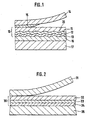
- Fig. 1 zeigt die Schichtfolge beim Transfervorgang eines Sicherheitselements 10 mit einer Beugungsstruktur 20 auf ein Substrat 17. Der Schichtaufbau des zu übertragenden Sicherheitselements 10 wurde auf einer separaten Trägerfolie 14 in Endlosform vorbereitet. Die Trägerfolie 14 wurde hierbei zuerst mit einer Releaseschicht 15 versehen, die für ein gutes und definiertes Ablösen des Sicherheitselements 10 beim Übertragungsvorgang sorgt. Auf dieser Schicht wurde die Schichtfolge des Sicherheitselements 10 angeordnet. Es besteht aus einer Kunststoffschicht 11, insbesondere einer mit UV-Strahlung härtbaren Lackschicht, in welche eine Beugungsstruktur20 in Form einer Reliefstruktur eingeprägt wurde. Um die Beugungsstruktur 20 in Reflexion sichtbar zu machen, ist auf der geprägten Lackschicht 11 eine spiegelnd reflektierende Metallschicht 13, wie z.B. eine Aluminiumschicht vorgesehen. Um eine gute Haftung zwischen der Kunststoffschicht 11 und der Aluminiumschicht 13 zu gewährleisten, wird erfindungsgemäß eine Hilfsschicht 12 zwischen der Lackschicht 11 und der Metallschicht 13 angeordnet. Der Übertrag des Sicherheitselements 10 erfolgt mit Hilfe einer Kleberschicht 16, die entweder bereits auf der Trägerfolie angeordnet oder kurz vor dem Übertrag auf das Substrat 17 aufgebracht wird. Hierbei kann es sich ebenfalls um eine vernetzbare Lackschicht, wie z.B. um einen kationisch härtenden Lack, einen blaulichthärtenden Lack aber auch um einen mit einer anderen Strahlung vernetzbaren Lack handeln. Die üblicherweise eingesetzten Heißschmelzkleber, die unter Einwirkung von Wärme und Druck für eine entsprechende Haftung am Substrat sorgen, können selbstverständlich ebenfalls eingesetzt werden.
- Auch hinsichtlich der Prägelackschicht 11 ist die Erfindung keinesweg auf die Verwendung UV-härtbarer Lacke beschränkt. Es können beliebige andere Lacke eingesetzt werden.
- Sofern zwischen der Metallschicht 13 und der Klebstoffschicht 16 ebenfalls Haftungsprobleme auftreten, kann zwischen diesen Schichten auch eine Hilfsschicht gemäß der Erfindung vorgesehen werden.
- Die Release-Schicht 15 auf der Trägerfolie 14 ist nicht obligatorisch. Ihre Verwendung und wenn ja, welche Art von Schicht eingesetzt wird, hängt von den jeweiligen Haftungsbedingungen zwischen Trägerfolie und Lackschicht ab.
- Statt dem Vakuumdampfverfahren kann für das Aufbringen der reflektierenden Metallschicht, die nicht notwendigerweise aus Aluminium bestehen muss, selbstverständlich auch ein anderes Verfahren, wie z.B. Galvanisieren verwendet werden.
- Unter Umständen kann es auch vorteilhaft sein, das Sicherheitselement 10 direkt auf dem Dokumentenmaterial zu erzeugen. Hierfürwird der Prägelack direkt auf das Substrat aufgebracht und dort mit der Beugungsstruktur geprägt. Nach dem Prägevorgang wird die haftvermittelnde Hilfsschicht nach einem beliebigen Verfahren möglichst dünn aufgebracht und mit der Aluminiumschicht, beispielsweise im Vakuumdampfverfahren, versehen. Gegebenenfalls können auf der Metallschicht weitere Schichten, wie eine Schutzschicht oder eine weitere Hilfsschicht zwischen Metall- und Schutzschicht, vorgesehen werden.
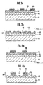
- Fig. 2 zeigt eine Variante der Erfindung, bei welcher eine Metallschicht mittels einer Lackschicht auf ein Substrat übertragen wird. Hier wird das Sicherheitselement 30 ebenfalls auf einer Trägerfolie 31 in Endlosform vorbereitet und anschließend mit Hilfe einer Klebstoffschicht auf das Substrat 35 übertragen. Auch hier kann es notwendig sein, zwischen der Trägerfolie 31 und der zu übertragenden Metallschicht 32 eine Releaseschicht vorzusehen, die in der Figur allerdings nicht gezeigt ist. Die Trägerfolie 31 wird anschließend mit der gewünschten Metallschicht 32 vollflächig bedampft. Um die Haftung der Metallschicht 32 an der als Klebstoff wirkenden Lackschicht 34 zu verbessern, wird die Metallschicht 32 zusätzlich mit einer dünnen Hilfsschicht 33 versehen, die, wie bereits erwähnt, beispielsweise eine Chromoder Aluminiumoxidschicht sein kann. Die Lackschicht 34 kann entweder auf diese Hilfsschicht 33 oder auf das Substrat 35 aufgetragen werden. Während des Kontakts zwischen Lackschicht 34 und Substrat 35 wird die Lackschicht 34 verfestigt, so dass die Metallschicht auf dem Substrat 35 haftet. Vernetzbare Klebstoffschichten sorgen hierbei aufgrund der Irreversibilität des Vernetzungsprozesses für einen unlösbaren Verbund zwischen Substrat und der Metallschicht 32. In einem letzten Schritt kann die Trägerfolie 31 abgezogen werden.
- Die Metallschicht muss nicht notwendigerweise vollflächig auf der Trägerschichtvorgesehen werden. Sie kann auch in Form von Zeichen oder Mustern aufgebracht werden oder Aussparungen in Form von Zeichen, Mustern oder dergleichen aufweisen. Sofern die Hilfsschicht nicht transparent ist, sollte diese in einem solchen Fall deckungsgleich zu der Metallschicht aufgebracht werden, um den optischen Eindruck des Sicherheitselements nicht zu stören. Für den Fall, dass die anorganische Hilfsschicht jedoch zumindest teilweise transparent ist, kann sie auch zur optischen Gestaltung des Sicherheitselements eingesetzt werden.
- Die Fig. 3a bis 4b zeigen die Herstellung eines derartigen erfindungsgemäßen Folienmaterials, welches eine Kunststoffschicht mit geprägter Oberfläche sowie einer hierauf angeordneten teilweisen Metallisierung enthält.
- Fig. 3a zeigt eine Trägerfolie 41, welche, wie bereits beschrieben, mit einer Prägelackschicht 42 versehen wurde, in welche eine Reliefstruktur, wie z.B, eine Beugungsstruktur eingeprägt wurde. Auf dieser Prägeschicht wurde erfindungsgemäß eine anorganische Hilfsschicht 43 angeordnet. Anschließend wurden die Bereiche der Hilfsschicht 43, die am fertigen Sicherheitselement 40 (Fig. 3b) metallfrei sein sollen, mit einer löslichen Druckfarbe 44 bedruckt. Anschließend wurde die gesamte Trägerfolie 41 mit einer vollflächigen Metallisierung 45 versehen. Dieser Schichtaufbau wird anschließend mit einem Lösungsmittel für die Druckfarbe 44 behandelt, so dass die Druckfarbe 44 und die im Bereich dieser Druckfarbe 44 befindliche Metallisierung 45 entfernt werden.
- Fig. 3b zeigt das erfindungsgemäße Folienmaterial nach dem Lösevorgang. Die Metallisierung 45 ist hier nurmehr in Teilbereichen, die anorganische Hilfsschicht 43 dagegen nach wie vor vollflächig vorhanden. Die metallschichtfreien Bereiche 46 können die Form von Buchstaben, Mustern oder dergleichen haben, die je nach Ausführung der Hilfsschicht transparent, teilreflektierend oder teiltransparent erscheinen können. Handelt es sich bei der Hilfsschicht beispielsweise um eine Metallschicht, so erscheinen die Aussparungen aufgrund der optischen Dichte < 1 der Hilfsschicht teiltransparent. Bei der Verwendung von Oxiden dagegen ergibt sich die Teiltransparenz bzw. Teilreflexion aus deren hoch brechenden Eigenschaften, insbesondere wenn die Oxide als sogenannte "dielektrische Spiegel" ausgeführt sind. In diesem Fall ergeben sich in Reflexion und Transmission auch besondere Farbeffekte.
- Gemäß einer Variante kann die lösliche Druckfarbe 44 auch unterhalb der Hilfsschicht 43 direkt auf die Prägeschicht 42 aufgedruckt werden. In diesem Fall wird nicht nur die Metallschicht 45 sondern auch die im Bereich der Druckfarbe befindliche Hilfsschicht 43 entfernt, so dass die metallschichtfreien Bereiche 46 in jedem Fall transparent erscheinen und durch die optischen Eigenschaften der Hilfsschicht 43 nicht beeinflusst werden.
- Eine weitere Verfahrensvariante zur Herstellung der metallschichtfreien Bereiche wird anhand der Fig. 4a und 4b näher erläutert. Auch hier wurde die Trägerfolie 51 mit einer geprägten Kunststoffschicht 52 sowie einer anorganischen Hilfsschicht 53 und einer vollflächigen Metallisierung 54 versehen (Fig. 4a). Im Anschluss hieran wurde eine lösungsmittelresistente Druckfarbe 55 in den Bereichen der Metallisierung aufgedruckt, die anschließend im Sicherheitselement 50 verbleiben sollen. Der so vorbehandelte Folienaufbau wird anschließend einem Lösungsmittel ausgesetzt, welches die nicht abgedeckten Bereiche der Metallisierung 54 sowie der Hilfsschicht 53 entfernt, nicht jedoch die durch die Abdeckschicht 55 geschützten Teile der Metallisierung 54 und der Hilfsschicht 53.
- Fig. 4b zeigt wieder das Folienmaterial mit dem fertigen Sicherheitselement 50. Die Prägeschicht 52 ist nach wie vor vollflächig vorhanden, die Hilfsschicht 53 sowie die Metallisierung 54 dagegen liegen nurmehr bereichsweise vor, so dass metallschichtfreie Teilbereiche 56 entstehen. Im gezeigten Fall ist nurmehr ein kleiner Teilbereich der Prägestruktur mit der Metallisierung 54 sowie der Hilfsschicht 53 versehen. Die Metallisierung kann dabei die Form von Zeichen oder Mustern aufweisen.
- Auch in diesem Beispiel ist es selbstverständlich möglich, ein Lösungsmittel zu verwenden, welches lediglich die Metallschicht 54, nicht aber die Hilfsschicht 53 löst und damit entfernt.
- Gemäß einer Variante ist es auch möglich, das Folienmaterial, nachdem die vollflächige Metallisierung aufgebracht wurde, direkt mit einer ätzenden Druckfarbe zu bedrucken, um die Metallschicht- bzw. metall- und hilfsschichtfreien Bereiche zu erzeugen.
- Der auf die beschriebene Weise hergestellte Folienschichtaufbau mit einer Teilmetallisierung kann selbstverständlich anschließend mit weiteren Schichten versehen werden, wie z.B. weiteren Hilfsschichten, Klebstoffschichten oder Schutzschichten, je nach Anwendungsfall des Sicherheitselementes.
Claims (28)
- Sicherheitselement, welches wenigstens eine Kunststoffschicht mit einer geprägten, optisch variablen Struktur sowie eine spiegelnd reflektierende Metallschicht aufweist, dadurch gekennzeichnet, dass zwischen der Kunststoffschicht und der Metallschicht eine anorganische Hilfsschicht angeordnet ist, die die Haftung zwischen der Metallschicht und der Kunststoffschicht erhöht.
- Sicherheitselement nach Anspruch 1, dadurch gekennzeichnet, dass die Hilfsschicht eine optische Dichte von maximal 1 aufweist.
- Sicherheitselement nach Anspruch 1 oder 2, dadurch gekennzeichnet, dass die Hilfsschicht ein Element oder eine Verbindung aus Elementen der II., III. und IV. Hauptgruppe sowie der 4. bis 6. Nebengruppe des Periodensystems ist.
- Sicherheitselement nach wenigstens einem der Ansprüche 1 bis 3, dadurch gekennzeichnet, dass die Hilfsschicht aus Titan (Ti), Chrom (Cr) oder Titannitrid (TiN) besteht.
- Sicherheitselement nach Anspruch 1 bis 3, dadurch gekennzeichnet, dass die Hilfsschicht ein Oxid der Elemente Aluminium (Al), Titan (Ti), Zirkonium (Zr), Zinn (Sn), Beryllium (Be), Chrom (Cr) oder Silizium (Si) ist.
- Sicherheitselement nach Anspruch 5, dadurch gekennzeichnet, dass die Hilfsschicht aus Al2O3, TiO2 oder Cr2O3 besteht.
- Sicherheitselement nach Anspruch 1 oder 2, dadurch gekennzeichnet, dass die Hilfsschicht aus einer Metallverbindung oder -legierung besteht.
- Sicherheitselement nach wenigstens einem der Ansprüche 1 bis 7, dadurch gekennzeichnet, dass die Kunststoffschicht eine Beugungsstruktur in Form einer Reliefstruktur aufweist.
- Sicherheitselement nach wenigstens einem der Ansprüche 1 bis 8, dadurch gekennzeichnet, dass das Sicherheitselement die Form eines Fadens oder Bandes aufweist.
- Sicherheitselement nach wenigstens einem der Ansprüche 1 bis 9, dadurch gekennzeichnet, dass die Kunststoffschicht eine mit UV-Strahlung vernetzbare Schicht ist.
- Sicherheitselement nach wenigstens einem der Ansprüche 1 bis 10, dadurch gekennzeichnet, dass die Metallschicht nur in Teilbereichen vorgesehen ist.
- Sicherheitselement nach wenigsten einem der Ansprüche 1 bis 11, dadurch gekennzeichnet, dass die Hilfsschicht deckungsgleich zur Metallschicht angeordnet ist.
- Sicherheitselement nach wenigstens einem der Ansprüche 1 bis 12, dadurch gekennzeichnet, dass die Metallschicht auf der von der Kunststoffschicht abgewandten Oberfläche ebenfalls mit einer Hilfsschicht versehen ist.
- Sicherheitsdokument, wie eine Banknote, Ausweiskarte oder dergl., dadurch gekennzeichnet, dass es zumindest ein Sicherheitselement gemäß wenigstens einem der Ansprüche 1 bis 13 aufweist.
- Sicherheitsdokument nach Anspruch 14, dadurch gekennzeichnet, dass das Sicherheitselement auf der Oberfläche des Sicherheitsdokuments angeordnet ist.
- Sicherheitsdokument nach Anspruch 14, dadurch gekennzeichnet, dass das Sicherheitselement zumindest teilweise in das Sicherheitsdokument eingebettet ist.
- Folienmaterial für Sicherheitselemente, mit einer Kunststofffolie, auf welcher eine Kunststoffschicht mit einer geprägten, optisch variablen Struktur sowie eine spiegelnd reflektierende Metallschicht angeordnet ist, dadurch gekennzeichnet, dass zwischen der Kunststoffschicht und der Metallschicht eine anorganische Hilfsschicht angeordnet ist, die die Haftung zwischen der Metallschicht und der Kunstststoffschicht erhöht.
- Verfahren zur Herstellung eines Folienmaterials für Sicherheitselemente nach Anspruch 17, gekennzeichnet durch folgende Schritte:- Bereitstellen einer Kunststofffolie in Endlosform als Trägerfolie,- Aufbringen einer Kunststoffschicht auf die Kunststofffolie,- Aufbringen einer anorganischen Hilfsschicht auf die Kunststoffschicht,- Aufbringen einerspiegelnd reflektierenden Metallschicht auf die anorganische Hilfsschicht durch Bedampfen, Galvanisieren oder chemisches Abscheiden.
- Verfahren nach Anspruch 18, dadurch gekennzeichnet, dass auf die Metallschicht eine weitere anorganische Hilfsschicht und gegebenenfalls weitere Kunststoffschichten aufgebracht werden.
- Verfahren nach Anspruch 18 oder 19, dadurch gekennzeichnet, dass zumindest die Metallschicht lediglich in Teilbereichen aufgebracht wird.
- Verfahen nach Anspruch 20, dadurch gekennzeichnet, dass die Metallschicht vollflächig aufgebracht und anschließend durch Bedrucken mit einer Ätzfarbe oder bereichsweises Abdecken und Wegätzen der nicht abgedeckten Bereiche teilweise entfernt wird.
- Verfahren nach Anspruch 20, dadurch gekennzeichnet, dass vor dem Aufbringen der Metallschicht bzw. vor dem Aufbringen der Hilfsschicht eine Druckfarbe in Form der metallfreien Bereiche aufgebracht wird, anschließend die Kunststofffolie vollflächig metallisiert und die Druckfarbe anschließend mit einem Lösungsmittel gelöst wird, so dass metallfreie Bereiche entstehen.
- Verfahren nach wenigstens einem der Ansprüche 18 bis 22, dadurch gekennzeichnet, dass als Hilfsschicht eine Chromschicht verwendet wird, die auf die Kunststoffschicht aufgedampft oder -gesputtert oder durch sonstige PVD-, CVD- sowie plasmagestützte Beschichtungsverfahren aufgebracht wird.
- Verfahren nach wenigstens einem der Ansprüche 18 bis 22, dadurch gekennzeichnet, dass als Hilfsschicht eine Aluminiumoxidschicht verwendet wird, die durch Aufsputtern einer Aluminiumschicht in Sauerstoffatmosphäre auf der Kunststoffschicht erzeugt wird.
- Verfahren nach wenigstens einem der Ansprüche 18 bis 24, dadurch gekennzeichnet, dass die Hilfsschicht in einer Dicke von weniger als 10 nm, vorzugsweise von 0,5 bis 5 nm, aufgebracht wird.
- Verfahren nach wenigstens einem der Ansprüche 18 bis 25, dadurch gekennzeichnet, dass als Metallschicht eine Aluminiumschicht verwendet wird, die in einer Dicke von 10 bis 40 nm erzeugt wird.
- Verfahren nach wenigstens einem der Ansprüche 18 bis 26, dadurch gekennzeichnet, dass in die Kunststoffschicht vor dem Aufbringen der Hilfsschicht eine Reliefstruktur eingeprägt wird.
- Verfahren nach wenigstens einem der Ansprüche 18 bis 27, dadurch gekennzeichnet, dass als Kunststoffschicht eine vernetzbare Kunststoffschicht verwendet wird.
Priority Applications (1)
| Application Number | Priority Date | Filing Date | Title |
|---|---|---|---|
| SI9830567T SI0944480T2 (sl) | 1997-10-10 | 1998-09-10 | Varnostni element in postopek za njegovo izdelavo |
Applications Claiming Priority (3)
| Application Number | Priority Date | Filing Date | Title |
|---|---|---|---|
| DE19744953A DE19744953A1 (de) | 1997-10-10 | 1997-10-10 | Sicherheitselement und Verfahren zu seiner Herstellung |
| DE19744953 | 1997-10-10 | ||
| PCT/EP1998/005787 WO1999019152A1 (de) | 1997-10-10 | 1998-09-10 | Sicherheitselement und verfahren zu seiner herstellung |
Publications (3)
| Publication Number | Publication Date |
|---|---|
| EP0944480A1 EP0944480A1 (de) | 1999-09-29 |
| EP0944480B1 EP0944480B1 (de) | 2003-08-27 |
| EP0944480B2 true EP0944480B2 (de) | 2006-11-15 |
Family
ID=7845249
Family Applications (1)
| Application Number | Title | Priority Date | Filing Date |
|---|---|---|---|
| EP98950024A Expired - Lifetime EP0944480B2 (de) | 1997-10-10 | 1998-09-10 | Sicherheitselement und verfahren zu seiner herstellung |
Country Status (10)
| Country | Link |
|---|---|
| US (2) | US6382677B1 (de) |
| EP (1) | EP0944480B2 (de) |
| AT (1) | ATE248071T1 (de) |
| AU (1) | AU9625198A (de) |
| DE (2) | DE19744953A1 (de) |
| DK (1) | DK0944480T4 (de) |
| ES (1) | ES2202900T5 (de) |
| PT (1) | PT944480E (de) |
| SI (1) | SI0944480T2 (de) |
| WO (1) | WO1999019152A1 (de) |
Cited By (1)
| Publication number | Priority date | Publication date | Assignee | Title |
|---|---|---|---|---|
| EP2524814B1 (de) | 2011-05-18 | 2015-03-25 | Landqart AG | Verbesserungen bei Sicherheitsfunktionen |
Families Citing this family (66)
| Publication number | Priority date | Publication date | Assignee | Title |
|---|---|---|---|---|
| US6615189B1 (en) | 1998-06-22 | 2003-09-02 | Bank One, Delaware, National Association | Debit purchasing of stored value card for use by and/or delivery to others |
| US7809642B1 (en) | 1998-06-22 | 2010-10-05 | Jpmorgan Chase Bank, N.A. | Debit purchasing of stored value card for use by and/or delivery to others |
| US7047883B2 (en) | 2002-07-15 | 2006-05-23 | Jds Uniphase Corporation | Method and apparatus for orienting magnetic flakes |
| US7667895B2 (en) | 1999-07-08 | 2010-02-23 | Jds Uniphase Corporation | Patterned structures with optically variable effects |
| US6761959B1 (en) | 1999-07-08 | 2004-07-13 | Flex Products, Inc. | Diffractive surfaces with color shifting backgrounds |
| DE19940790B4 (de) * | 1999-08-27 | 2004-12-09 | Leonhard Kurz Gmbh & Co | Übertragungsfolie zur Aufbringung einer Dekorschichtanordnung auf ein Substrat sowie Verfahren zu deren Herstellung |
| US8793160B2 (en) | 1999-12-07 | 2014-07-29 | Steve Sorem | System and method for processing transactions |
| US11768321B2 (en) | 2000-01-21 | 2023-09-26 | Viavi Solutions Inc. | Optically variable security devices |
| WO2002011019A1 (en) | 2000-08-01 | 2002-02-07 | First Usa Bank, N.A. | System and method for transponder-enabled account transactions |
| BR0114432B1 (pt) * | 2000-10-09 | 2011-04-05 | processo para produção de uma folha metalizada, e, folha metalizada. | |
| DE10064616C2 (de) * | 2000-12-22 | 2003-02-06 | Ovd Kinegram Ag Zug | Dekorfolie und Verfahren zum Beschriften der Dekorfolie |
| AU2002327322A1 (en) | 2001-07-24 | 2003-02-17 | First Usa Bank, N.A. | Multiple account card and transaction routing |
| US7625632B2 (en) | 2002-07-15 | 2009-12-01 | Jds Uniphase Corporation | Alignable diffractive pigment flakes and method and apparatus for alignment and images formed therefrom |
| US8020754B2 (en) | 2001-08-13 | 2011-09-20 | Jpmorgan Chase Bank, N.A. | System and method for funding a collective account by use of an electronic tag |
| US7899753B1 (en) | 2002-03-25 | 2011-03-01 | Jpmorgan Chase Bank, N.A | Systems and methods for time variable financial authentication |
| AU2003230751A1 (en) | 2002-03-29 | 2003-10-13 | Bank One, Delaware, N.A. | System and process for performing purchase transaction using tokens |
| GB0209564D0 (en) * | 2002-04-25 | 2002-06-05 | Rue De Int Ltd | Improvements in substrates |
| DE10218897A1 (de) * | 2002-04-26 | 2003-11-06 | Giesecke & Devrient Gmbh | Sicherheitselement und Verfahren zu seiner Herstellung |
| US11230127B2 (en) | 2002-07-15 | 2022-01-25 | Viavi Solutions Inc. | Method and apparatus for orienting magnetic flakes |
| US7934451B2 (en) | 2002-07-15 | 2011-05-03 | Jds Uniphase Corporation | Apparatus for orienting magnetic flakes |
| US8025952B2 (en) | 2002-09-13 | 2011-09-27 | Jds Uniphase Corporation | Printed magnetic ink overt security image |
| US9164575B2 (en) | 2002-09-13 | 2015-10-20 | Jds Uniphase Corporation | Provision of frames or borders around pigment flakes for covert security applications |
| US7674501B2 (en) | 2002-09-13 | 2010-03-09 | Jds Uniphase Corporation | Two-step method of coating an article for security printing by application of electric or magnetic field |
| US9458324B2 (en) | 2002-09-13 | 2016-10-04 | Viava Solutions Inc. | Flakes with undulate borders and method of forming thereof |
| US7809595B2 (en) | 2002-09-17 | 2010-10-05 | Jpmorgan Chase Bank, Na | System and method for managing risks associated with outside service providers |
| US20040122736A1 (en) | 2002-10-11 | 2004-06-24 | Bank One, Delaware, N.A. | System and method for granting promotional rewards to credit account holders |
| DE10248868A1 (de) * | 2002-10-18 | 2004-07-08 | Giesecke & Devrient Gmbh | Wertdokument |
| US7823777B2 (en) * | 2003-01-03 | 2010-11-02 | American Express Travel Related Services Company, Inc. | Metal-containing transaction card and method of making same |
| US7588184B2 (en) * | 2003-01-03 | 2009-09-15 | American Express Travel Related Services Company, Inc. | Metal-containing transaction card and method of making the same |
| US8033457B2 (en) | 2003-01-03 | 2011-10-11 | American Express Travel Related Services Company, Inc. | Metal-containing transaction card and method of making the same |
| JP4365326B2 (ja) | 2003-01-03 | 2009-11-18 | アメリカン エクスプレス トラベル リレイテッド サービシーズ カンパニー, インコーポレイテッド | 金属を包含したトランザクションカード及びそれを作成する方法 |
| US8306907B2 (en) | 2003-05-30 | 2012-11-06 | Jpmorgan Chase Bank N.A. | System and method for offering risk-based interest rates in a credit instrument |
| US7550197B2 (en) | 2003-08-14 | 2009-06-23 | Jds Uniphase Corporation | Non-toxic flakes for authentication of pharmaceutical articles |
| US20050196604A1 (en) * | 2004-03-05 | 2005-09-08 | Unifoil Corporation | Metallization process and product produced thereby |
| US20050244977A1 (en) * | 2004-03-24 | 2005-11-03 | Drachev Vladimir P | Adaptive metal films for detection of biomolecules |
| US20060097513A1 (en) * | 2004-07-01 | 2006-05-11 | Caldwell Mason A | Identification Label |
| DE102004042136B4 (de) * | 2004-08-30 | 2006-11-09 | Ovd Kinegram Ag | Metallisiertes Sicherheitselement |
| FI20045369A7 (fi) * | 2004-10-01 | 2006-04-02 | Avantone Oy | Suojatun mikrorakennealueen käsittävä tuote sekä menetelmä ja laite sen tuottamiseksi |
| CA2541568C (en) | 2005-04-06 | 2014-05-13 | Jds Uniphase Corporation | Dynamic appearance-changing optical devices (dacod) printed in a shaped magnetic field including printable fresnel structures |
| US7401731B1 (en) | 2005-05-27 | 2008-07-22 | Jpmorgan Chase Bank, Na | Method and system for implementing a card product with multiple customized relationships |
| AT502021B1 (de) * | 2005-06-01 | 2007-01-15 | Hueck Folien Gmbh | Sicherheitselemente mit funktionsschichten und verfahren zu deren herstellung |
| ITMI20051944A1 (it) * | 2005-10-14 | 2007-04-15 | Fabriano Securities Srl | Elemento di sicurezza per banconote o documenti rappresentanti un valore |
| CA2564764C (en) | 2005-10-25 | 2014-05-13 | Jds Uniphase Corporation | Patterned optical structures with enhanced security feature |
| US12204120B2 (en) | 2006-03-06 | 2025-01-21 | Viavi Solutions Inc. | Optically variable security devices |
| CA2592667C (en) | 2006-07-12 | 2014-05-13 | Jds Uniphase Corporation | Stamping a coating of cured field aligned special effect flakes and image formed thereby |
| JP2009178843A (ja) * | 2006-08-22 | 2009-08-13 | Rynne Group Llc | 識別カードおよびその識別カードを使用した識別カード取引システム |
| JP2009193069A (ja) | 2008-02-13 | 2009-08-27 | Jds Uniphase Corp | 光学的な特殊効果フレークを含むレーザ印刷用の媒体 |
| USD635186S1 (en) | 2008-06-30 | 2011-03-29 | Jpmorgan Chase Bank, N.A. | Metal transaction device |
| US9305292B1 (en) | 2008-07-03 | 2016-04-05 | Jpmorgan Chase Bank, N.A. | Systems and methods for providing an adaptable transponder device |
| USD636021S1 (en) | 2008-07-17 | 2011-04-12 | Jpmorgan Chase Bank, N.A. | Eco-friendly transaction device |
| JP2012507039A (ja) * | 2008-10-27 | 2012-03-22 | ドゥ ラ リュ インターナショナル リミティド | パターンの形式の印刷金属層を有するセキュリティ装置およびその製造方法 |
| USD602986S1 (en) | 2009-03-06 | 2009-10-27 | Jpmorgan Chase Bank, N.A. | Metal transaction device |
| US8725589B1 (en) | 2009-07-30 | 2014-05-13 | Jpmorgan Chase Bank, N.A. | Methods for personalizing multi-layer transaction cards |
| USD623690S1 (en) | 2010-03-05 | 2010-09-14 | Jpmorgan Chase Bank, N.A. | Metal transaction device with gem-like surface |
| US20110223389A1 (en) * | 2010-03-10 | 2011-09-15 | Chun-Hsu Lin | Decorative film, method for manufacturing thereof, and decorative molding article |
| USD643064S1 (en) | 2010-07-29 | 2011-08-09 | Jpmorgan Chase Bank, N.A. | Metal transaction device with gem-like surface |
| CN103088289A (zh) * | 2011-10-31 | 2013-05-08 | 深圳富泰宏精密工业有限公司 | 壳体的制备方法及由该方法所制得的壳体 |
| CA3217881A1 (en) | 2012-01-12 | 2013-07-18 | Viavi Solutions Inc. | Article with a dynamic frame formed with aligned pigment flakes |
| ITRM20130007A1 (it) * | 2013-01-07 | 2014-07-08 | Zecca Dello Ist Poligrafico | Metodo di realizzazione di microelementi metallici diffrattivi variabili in un corpo plastico laminabile. |
| GB2510381B (en) * | 2013-02-01 | 2015-11-04 | Rue De Int Ltd | Security devices and methods of manufacture thereof |
| USD854083S1 (en) | 2013-03-27 | 2019-07-16 | Jpmorgan Chase Bank, N.A. | Hybrid transaction device |
| DE102014018890A1 (de) | 2014-12-17 | 2016-06-23 | Giesecke & Devrient Gmbh | Sicherheitselement, Verfahren zum Herstellen desselben und mit dem Sicherheitselement ausgestatteter Datenträger |
| US20160232438A1 (en) | 2015-02-06 | 2016-08-11 | American Express Travel Related Services Company, Inc. | Ceramic-containing transaction cards |
| DE102018130347A1 (de) * | 2018-11-29 | 2020-06-04 | Bayerische Motoren Werke Aktiengesellschaft | Fahrzeugbauteil und Verfahren zur Herstellung eines Fahrzeugbauteils |
| CN112391658A (zh) * | 2021-01-21 | 2021-02-23 | 宁波四维尔工业有限责任公司 | 一种塑料电镀的前处理工艺 |
| DE102023125600A1 (de) * | 2023-09-21 | 2025-03-27 | Giesecke+Devrient Currency Technology Gmbh | Verfahren zum Herstellen eines Sicherheitselementes mit Reliefstruktur und Sicherheitselement mit Reliefstruktur |
Citations (9)
| Publication number | Priority date | Publication date | Assignee | Title |
|---|---|---|---|---|
| DE2800635B1 (de) † | 1978-01-07 | 1979-04-26 | Kurz Leonhard Fa | Praegefolie,insbesondere Heisspraegefolie |
| DE3308831A1 (de) † | 1982-11-08 | 1984-05-10 | American Bank Note Co., New York, N.Y. | Verfahren zum herstellen einer erkennbaren lichtbeugenden struktur und danach hergestellter lesbarer aufzeichnungstraeger |
| CH678835A5 (de) † | 1991-01-18 | 1991-11-15 | Landis & Gyr Betriebs Ag | |
| DE4039352A1 (de) † | 1990-12-10 | 1992-06-11 | Leybold Ag | Verfahren und vorrichtung zur herstellung von schichten auf oberflaechen von werkstoffen |
| WO1994018003A1 (en) † | 1993-02-05 | 1994-08-18 | Southwall Technologies Inc. | Metal on plastic films with adhesion-promoting layer |
| US5361172A (en) † | 1993-01-21 | 1994-11-01 | Midwest Research Institute | Durable metallized polymer mirror |
| DE4344553A1 (de) † | 1993-12-24 | 1995-06-29 | Giesecke & Devrient Gmbh | Sicherheitspapier mit einem faden- oder bandförmigen Sicherheitselement sowie Verfahren zur Herstellung desselben |
| JPH096219A (ja) † | 1995-06-22 | 1997-01-10 | Toppan Printing Co Ltd | ホログラム転写箔 |
| EP0987599A2 (de) † | 1998-09-16 | 2000-03-22 | MANTEGAZZA ANTONIO ARTI GRAFICHE S.r.l. | Hochauflösendes Druckverfahren, insbesondere für Sicherheitsmarkierungen auf Banknoten und dergleichen |
Family Cites Families (14)
| Publication number | Priority date | Publication date | Assignee | Title |
|---|---|---|---|---|
| JP2775647B2 (ja) * | 1989-11-17 | 1998-07-16 | 宇部興産株式会社 | メタライズドポリイミドフィルムの製法 |
| US5078801A (en) * | 1990-08-14 | 1992-01-07 | Intel Corporation | Post-polish cleaning of oxidized substrates by reverse colloidation |
| GB2250474B (en) * | 1990-12-04 | 1994-04-20 | Portals Ltd | Security articles |
| US6333084B1 (en) * | 1994-09-09 | 2001-12-25 | Southwall Technologies, Inc. | Double-sided reflector films |
| DE19529171A1 (de) * | 1995-08-08 | 1997-02-13 | Giesecke & Devrient Gmbh | Transferband |
| US5575706A (en) * | 1996-01-11 | 1996-11-19 | Taiwan Semiconductor Manufacturing Company Ltd. | Chemical/mechanical planarization (CMP) apparatus and polish method |
| US5815292A (en) * | 1996-02-21 | 1998-09-29 | Advanced Deposition Technologies, Inc. | Low cost diffraction images for high security application |
| US6007696A (en) * | 1996-09-28 | 1999-12-28 | Kabushiki Kaisha Toshiba | Apparatus and method for manufacturing electrolytic ionic water and washing method using electroyltic ionic water |
| JP3568709B2 (ja) * | 1996-09-30 | 2004-09-22 | 株式会社東芝 | 超純水の純化方法及び純化装置 |
| JPH10144650A (ja) * | 1996-11-11 | 1998-05-29 | Mitsubishi Electric Corp | 半導体材料の洗浄装置 |
| JP3455035B2 (ja) * | 1996-11-14 | 2003-10-06 | 株式会社東芝 | 電解イオン水生成装置及び半導体製造装置 |
| US6022400A (en) * | 1997-05-22 | 2000-02-08 | Nippon Steel Corporation | Polishing abrasive grains, polishing agent and polishing method |
| US5934980A (en) * | 1997-06-09 | 1999-08-10 | Micron Technology, Inc. | Method of chemical mechanical polishing |
| JP3701126B2 (ja) * | 1998-09-01 | 2005-09-28 | 株式会社荏原製作所 | 基板の洗浄方法及び研磨装置 |
-
1997
- 1997-10-10 DE DE19744953A patent/DE19744953A1/de not_active Withdrawn
-
1998
- 1998-09-10 DK DK98950024T patent/DK0944480T4/da active
- 1998-09-10 PT PT98950024T patent/PT944480E/pt unknown
- 1998-09-10 ES ES98950024T patent/ES2202900T5/es not_active Expired - Lifetime
- 1998-09-10 WO PCT/EP1998/005787 patent/WO1999019152A1/de not_active Ceased
- 1998-09-10 DE DE59809415T patent/DE59809415D1/de not_active Expired - Lifetime
- 1998-09-10 SI SI9830567T patent/SI0944480T2/sl unknown
- 1998-09-10 AU AU96251/98A patent/AU9625198A/en not_active Abandoned
- 1998-09-10 US US09/308,680 patent/US6382677B1/en not_active Expired - Lifetime
- 1998-09-10 AT AT98950024T patent/ATE248071T1/de not_active IP Right Cessation
- 1998-09-10 EP EP98950024A patent/EP0944480B2/de not_active Expired - Lifetime
-
2002
- 2002-02-28 US US10/084,431 patent/US6726813B2/en not_active Expired - Fee Related
Patent Citations (11)
| Publication number | Priority date | Publication date | Assignee | Title |
|---|---|---|---|---|
| DE2800635B1 (de) † | 1978-01-07 | 1979-04-26 | Kurz Leonhard Fa | Praegefolie,insbesondere Heisspraegefolie |
| DE3308831A1 (de) † | 1982-11-08 | 1984-05-10 | American Bank Note Co., New York, N.Y. | Verfahren zum herstellen einer erkennbaren lichtbeugenden struktur und danach hergestellter lesbarer aufzeichnungstraeger |
| DE4039352A1 (de) † | 1990-12-10 | 1992-06-11 | Leybold Ag | Verfahren und vorrichtung zur herstellung von schichten auf oberflaechen von werkstoffen |
| CH678835A5 (de) † | 1991-01-18 | 1991-11-15 | Landis & Gyr Betriebs Ag | |
| DE4130896A1 (de) † | 1991-01-18 | 1992-07-23 | Landis & Gyr Betriebs Ag | Schichtverbund mit beugungsstrukturen |
| US5361172A (en) † | 1993-01-21 | 1994-11-01 | Midwest Research Institute | Durable metallized polymer mirror |
| WO1994018003A1 (en) † | 1993-02-05 | 1994-08-18 | Southwall Technologies Inc. | Metal on plastic films with adhesion-promoting layer |
| US5589280A (en) † | 1993-02-05 | 1996-12-31 | Southwall Technologies Inc. | Metal on plastic films with adhesion-promoting layer |
| DE4344553A1 (de) † | 1993-12-24 | 1995-06-29 | Giesecke & Devrient Gmbh | Sicherheitspapier mit einem faden- oder bandförmigen Sicherheitselement sowie Verfahren zur Herstellung desselben |
| JPH096219A (ja) † | 1995-06-22 | 1997-01-10 | Toppan Printing Co Ltd | ホログラム転写箔 |
| EP0987599A2 (de) † | 1998-09-16 | 2000-03-22 | MANTEGAZZA ANTONIO ARTI GRAFICHE S.r.l. | Hochauflösendes Druckverfahren, insbesondere für Sicherheitsmarkierungen auf Banknoten und dergleichen |
Non-Patent Citations (2)
| Title |
|---|
| L. Holland: "Vacuum Deposition of Thin Films", Chapman and Hall Ltd., Hochschule Linz, Institut für Physik, 1970 † |
| W. Meckbach: "Preparation of Unbacked Cadmium Foils of Approximately 50 µg/cm²", Rev. Sci. Instr. 34, p. 188, 1963 † |
Cited By (1)
| Publication number | Priority date | Publication date | Assignee | Title |
|---|---|---|---|---|
| EP2524814B1 (de) | 2011-05-18 | 2015-03-25 | Landqart AG | Verbesserungen bei Sicherheitsfunktionen |
Also Published As
| Publication number | Publication date |
|---|---|
| AU9625198A (en) | 1999-05-03 |
| SI0944480T1 (en) | 2004-04-30 |
| ES2202900T3 (es) | 2004-04-01 |
| EP0944480B1 (de) | 2003-08-27 |
| DK0944480T4 (da) | 2007-03-19 |
| ES2202900T5 (es) | 2007-05-01 |
| US6726813B2 (en) | 2004-04-27 |
| DE19744953A1 (de) | 1999-04-15 |
| DE59809415D1 (de) | 2003-10-02 |
| DK0944480T3 (da) | 2003-12-22 |
| SI0944480T2 (sl) | 2007-04-30 |
| ATE248071T1 (de) | 2003-09-15 |
| PT944480E (pt) | 2003-12-31 |
| US6382677B1 (en) | 2002-05-07 |
| EP0944480A1 (de) | 1999-09-29 |
| US20020117846A1 (en) | 2002-08-29 |
| WO1999019152A1 (de) | 1999-04-22 |
Similar Documents
| Publication | Publication Date | Title |
|---|---|---|
| EP0944480B2 (de) | Sicherheitselement und verfahren zu seiner herstellung | |
| EP1744904B1 (de) | Folienmaterial und verfahren zu seiner herstellung | |
| EP2004420B1 (de) | Sicherheitselement und verfahren zu seiner herstellung | |
| EP2123471B1 (de) | Sicherheitselement und Verfahren zu seiner Herstellung | |
| EP1478520B2 (de) | Sicherheitsdokument und sicherheitselement für ein sicherheitsdokument | |
| EP1476315B1 (de) | Sicherheitselement und sicherheitsdokument mit einem solchen sicherheitselement | |
| EP1259383B2 (de) | Mehrschichtige, laminierte karte mit eingelagertem, reliefstrukturen aufweisenden sicherheitselement | |
| DE102005006231B4 (de) | Verfahren zur Herstellung eines Mehrschichtkörpers | |
| DE4313521C1 (de) | Dekorationsschichtaufbau und dessen Verwendung | |
| EP3643511B1 (de) | Sicherheitselement und mit dem sicherheitselement ausgestatteter datenträger | |
| AT507975B1 (de) | Sicherheitsfolie oder sicherheitsetikett mit manipulationsnachweis | |
| EP2173571A2 (de) | Sicherheitselement | |
| EP2147354B1 (de) | Verfahren zur herstellung von personal- oder wertdokumenten mit einem personalisierten hologramm und damit hergestelltes personal- oder wertdokument | |
| EP3727871B1 (de) | Wertdokument | |
| EP4217207A1 (de) | Verfahren zum herstellen eines optisch variablen sicherheitselements | |
| DE112004002006B4 (de) | Sicherheitselement und Verfahren zu seiner Herstellung | |
| EP2159071B2 (de) | Sicherheitselement, das ohne Hilfsmittel verifiziert werden kann | |
| EP4461555A1 (de) | Sicherheitselement mit motivbildender flüssigkristallschicht |
Legal Events
| Date | Code | Title | Description |
|---|---|---|---|
| PUAI | Public reference made under article 153(3) epc to a published international application that has entered the european phase |
Free format text: ORIGINAL CODE: 0009012 |
|
| AK | Designated contracting states |
Kind code of ref document: A1 Designated state(s): AT BE CH CY DE DK ES FI FR GB GR IE IT LI LU MC NL PT SE |
|
| AX | Request for extension of the european patent |
Free format text: SI PAYMENT 19990712 |
|
| 17P | Request for examination filed |
Effective date: 19991022 |
|
| 17Q | First examination report despatched |
Effective date: 20020705 |
|
| GRAH | Despatch of communication of intention to grant a patent |
Free format text: ORIGINAL CODE: EPIDOS IGRA |
|
| GRAS | Grant fee paid |
Free format text: ORIGINAL CODE: EPIDOSNIGR3 |
|
| GRAA | (expected) grant |
Free format text: ORIGINAL CODE: 0009210 |
|
| AK | Designated contracting states |
Designated state(s): AT BE CH CY DE DK ES FI FR GB GR IE IT LI LU MC NL PT SE |
|
| AX | Request for extension of the european patent |
Extension state: SI |
|
| REG | Reference to a national code |
Ref country code: GB Ref legal event code: FG4D Free format text: NOT ENGLISH |
|
| REG | Reference to a national code |
Ref country code: CH Ref legal event code: EP |
|
| REG | Reference to a national code |
Ref country code: SE Ref legal event code: TRGR |
|
| REG | Reference to a national code |
Ref country code: CH Ref legal event code: NV Representative=s name: PATENTANWAELTE FELDMANN & PARTNER AG |
|
| GBT | Gb: translation of ep patent filed (gb section 77(6)(a)/1977) | ||
| REG | Reference to a national code |
Ref country code: IE Ref legal event code: FG4D Free format text: GERMAN |
|
| REF | Corresponds to: |
Ref document number: 59809415 Country of ref document: DE Date of ref document: 20031002 Kind code of ref document: P |
|
| REG | Reference to a national code |
Ref country code: DK Ref legal event code: T3 Ref country code: GR Ref legal event code: EP Ref document number: 20030404679 Country of ref document: GR |
|
| REG | Reference to a national code |
Ref country code: SE Ref legal event code: TRGR |
|
| ET | Fr: translation filed | ||
| PLBQ | Unpublished change to opponent data |
Free format text: ORIGINAL CODE: EPIDOS OPPO |
|
| PLBI | Opposition filed |
Free format text: ORIGINAL CODE: 0009260 |
|
| PLBQ | Unpublished change to opponent data |
Free format text: ORIGINAL CODE: EPIDOS OPPO |
|
| PLBI | Opposition filed |
Free format text: ORIGINAL CODE: 0009260 |
|
| PLAX | Notice of opposition and request to file observation + time limit sent |
Free format text: ORIGINAL CODE: EPIDOSNOBS2 |
|
| 26 | Opposition filed |
Opponent name: LEONHARD KURZ GMBH & CO.KG Effective date: 20040524 |
|
| 26 | Opposition filed |
Opponent name: HUECK FOLIEN GMBH Effective date: 20040527 Opponent name: LEONHARD KURZ GMBH & CO.KG Effective date: 20040524 |
|
| NLR1 | Nl: opposition has been filed with the epo |
Opponent name: HUECK FOLIEN GMBH Opponent name: LEONHARD KURZ GMBH & CO.KG |
|
| PLAX | Notice of opposition and request to file observation + time limit sent |
Free format text: ORIGINAL CODE: EPIDOSNOBS2 |
|
| PLAX | Notice of opposition and request to file observation + time limit sent |
Free format text: ORIGINAL CODE: EPIDOSNOBS2 |
|
| REG | Reference to a national code |
Ref country code: SI Ref legal event code: IF |
|
| PLBB | Reply of patent proprietor to notice(s) of opposition received |
Free format text: ORIGINAL CODE: EPIDOSNOBS3 |
|
| PLBP | Opposition withdrawn |
Free format text: ORIGINAL CODE: 0009264 |
|
| PLBP | Opposition withdrawn |
Free format text: ORIGINAL CODE: 0009264 |
|
| PGFP | Annual fee paid to national office [announced via postgrant information from national office to epo] |
Ref country code: CY Payment date: 20060727 Year of fee payment: 9 |
|
| PGFP | Annual fee paid to national office [announced via postgrant information from national office to epo] |
Ref country code: PT Payment date: 20060901 Year of fee payment: 9 |
|
| PGFP | Annual fee paid to national office [announced via postgrant information from national office to epo] |
Ref country code: MC Payment date: 20060920 Year of fee payment: 9 |
|
| PGFP | Annual fee paid to national office [announced via postgrant information from national office to epo] |
Ref country code: FI Payment date: 20060921 Year of fee payment: 9 |
|
| PGFP | Annual fee paid to national office [announced via postgrant information from national office to epo] |
Ref country code: IE Payment date: 20060925 Year of fee payment: 9 Ref country code: GR Payment date: 20060925 Year of fee payment: 9 Ref country code: DK Payment date: 20060925 Year of fee payment: 9 |
|
| PUAH | Patent maintained in amended form |
Free format text: ORIGINAL CODE: 0009272 |
|
| STAA | Information on the status of an ep patent application or granted ep patent |
Free format text: STATUS: PATENT MAINTAINED AS AMENDED |
|
| 27A | Patent maintained in amended form |
Effective date: 20061115 |
|
| AK | Designated contracting states |
Kind code of ref document: B2 Designated state(s): AT BE CH CY DE DK ES FI FR GB GR IE IT LI LU MC NL PT SE |
|
| AX | Request for extension of the european patent |
Extension state: SI |
|
| REG | Reference to a national code |
Ref country code: CH Ref legal event code: AEN Free format text: AUFRECHTERHALTUNG DES PATENTES IN GEAENDERTER FORM |
|
| NLR2 | Nl: decision of opposition |
Effective date: 20061115 |
|
| REG | Reference to a national code |
Ref country code: SE Ref legal event code: RPEO |
|
| GBTA | Gb: translation of amended ep patent filed (gb section 77(6)(b)/1977) | ||
| REG | Reference to a national code |
Ref country code: DK Ref legal event code: T4 |
|
| REG | Reference to a national code |
Ref country code: GR Ref legal event code: EP Ref document number: 20070400372 Country of ref document: GR |
|
| ET3 | Fr: translation filed ** decision concerning opposition | ||
| NLR3 | Nl: receipt of modified translations in the netherlands language after an opposition procedure | ||
| REG | Reference to a national code |
Ref country code: ES Ref legal event code: DC2A Date of ref document: 20061129 Kind code of ref document: T5 |
|
| REG | Reference to a national code |
Ref country code: PT Ref legal event code: MM4A Free format text: LAPSE DUE TO NON-PAYMENT OF FEES Effective date: 20080310 |
|
| PG25 | Lapsed in a contracting state [announced via postgrant information from national office to epo] |
Ref country code: MC Free format text: LAPSE BECAUSE OF NON-PAYMENT OF DUE FEES Effective date: 20070930 |
|
| REG | Reference to a national code |
Ref country code: DK Ref legal event code: EBP |
|
| PG25 | Lapsed in a contracting state [announced via postgrant information from national office to epo] |
Ref country code: PT Free format text: LAPSE BECAUSE OF NON-PAYMENT OF DUE FEES Effective date: 20080310 Ref country code: FI Free format text: LAPSE BECAUSE OF NON-PAYMENT OF DUE FEES Effective date: 20070910 |
|
| REG | Reference to a national code |
Ref country code: IE Ref legal event code: MM4A |
|
| PG25 | Lapsed in a contracting state [announced via postgrant information from national office to epo] |
Ref country code: CY Free format text: LAPSE BECAUSE OF NON-PAYMENT OF DUE FEES Effective date: 20070910 |
|
| PG25 | Lapsed in a contracting state [announced via postgrant information from national office to epo] |
Ref country code: IE Free format text: LAPSE BECAUSE OF NON-PAYMENT OF DUE FEES Effective date: 20070910 Ref country code: GR Free format text: LAPSE BECAUSE OF NON-PAYMENT OF DUE FEES Effective date: 20070216 Ref country code: DK Free format text: LAPSE BECAUSE OF NON-PAYMENT OF DUE FEES Effective date: 20071001 |
|
| PGFP | Annual fee paid to national office [announced via postgrant information from national office to epo] |
Ref country code: LU Payment date: 20080923 Year of fee payment: 11 Ref country code: ES Payment date: 20080922 Year of fee payment: 11 |
|
| PGFP | Annual fee paid to national office [announced via postgrant information from national office to epo] |
Ref country code: NL Payment date: 20080922 Year of fee payment: 11 |
|
| PGFP | Annual fee paid to national office [announced via postgrant information from national office to epo] |
Ref country code: BE Payment date: 20080924 Year of fee payment: 11 |
|
| PGFP | Annual fee paid to national office [announced via postgrant information from national office to epo] |
Ref country code: SE Payment date: 20090922 Year of fee payment: 12 Ref country code: AT Payment date: 20090921 Year of fee payment: 12 |
|
| BERE | Be: lapsed |
Owner name: *GIESECKE & DEVRIENT G.M.B.H. Effective date: 20090930 |
|
| REG | Reference to a national code |
Ref country code: NL Ref legal event code: V1 Effective date: 20100401 |
|
| PG25 | Lapsed in a contracting state [announced via postgrant information from national office to epo] |
Ref country code: NL Free format text: LAPSE BECAUSE OF NON-PAYMENT OF DUE FEES Effective date: 20100401 |
|
| PG25 | Lapsed in a contracting state [announced via postgrant information from national office to epo] |
Ref country code: BE Free format text: LAPSE BECAUSE OF NON-PAYMENT OF DUE FEES Effective date: 20090930 |
|
| REG | Reference to a national code |
Ref country code: SI Ref legal event code: KO00 Effective date: 20100819 |
|
| PG25 | Lapsed in a contracting state [announced via postgrant information from national office to epo] |
Ref country code: LU Free format text: LAPSE BECAUSE OF NON-PAYMENT OF DUE FEES Effective date: 20090910 |
|
| REG | Reference to a national code |
Ref country code: SE Ref legal event code: EUG |
|
| REG | Reference to a national code |
Ref country code: ES Ref legal event code: FD2A Effective date: 20110718 |
|
| PG25 | Lapsed in a contracting state [announced via postgrant information from national office to epo] |
Ref country code: ES Free format text: LAPSE BECAUSE OF NON-PAYMENT OF DUE FEES Effective date: 20110706 |
|
| PG25 | Lapsed in a contracting state [announced via postgrant information from national office to epo] |
Ref country code: AT Free format text: LAPSE BECAUSE OF NON-PAYMENT OF DUE FEES Effective date: 20100910 |
|
| PG25 | Lapsed in a contracting state [announced via postgrant information from national office to epo] |
Ref country code: ES Free format text: LAPSE BECAUSE OF NON-PAYMENT OF DUE FEES Effective date: 20090911 |
|
| PG25 | Lapsed in a contracting state [announced via postgrant information from national office to epo] |
Ref country code: SE Free format text: LAPSE BECAUSE OF NON-PAYMENT OF DUE FEES Effective date: 20100911 |
|
| PGFP | Annual fee paid to national office [announced via postgrant information from national office to epo] |
Ref country code: DE Payment date: 20130930 Year of fee payment: 16 Ref country code: CH Payment date: 20130923 Year of fee payment: 16 |
|
| PGFP | Annual fee paid to national office [announced via postgrant information from national office to epo] |
Ref country code: IT Payment date: 20130924 Year of fee payment: 16 |
|
| PGFP | Annual fee paid to national office [announced via postgrant information from national office to epo] |
Ref country code: FR Payment date: 20130918 Year of fee payment: 16 |
|
| REG | Reference to a national code |
Ref country code: DE Ref legal event code: R082 Ref document number: 59809415 Country of ref document: DE |
|
| PGFP | Annual fee paid to national office [announced via postgrant information from national office to epo] |
Ref country code: GB Payment date: 20140923 Year of fee payment: 17 |
|
| REG | Reference to a national code |
Ref country code: DE Ref legal event code: R119 Ref document number: 59809415 Country of ref document: DE |
|
| REG | Reference to a national code |
Ref country code: CH Ref legal event code: PL |
|
| REG | Reference to a national code |
Ref country code: DE Ref legal event code: R119 Ref document number: 59809415 Country of ref document: DE Effective date: 20150401 |
|
| REG | Reference to a national code |
Ref country code: FR Ref legal event code: ST Effective date: 20150529 |
|
| PG25 | Lapsed in a contracting state [announced via postgrant information from national office to epo] |
Ref country code: LI Free format text: LAPSE BECAUSE OF NON-PAYMENT OF DUE FEES Effective date: 20140930 Ref country code: DE Free format text: LAPSE BECAUSE OF NON-PAYMENT OF DUE FEES Effective date: 20150401 Ref country code: CH Free format text: LAPSE BECAUSE OF NON-PAYMENT OF DUE FEES Effective date: 20140930 |
|
| PG25 | Lapsed in a contracting state [announced via postgrant information from national office to epo] |
Ref country code: IT Free format text: LAPSE BECAUSE OF NON-PAYMENT OF DUE FEES Effective date: 20140910 Ref country code: FR Free format text: LAPSE BECAUSE OF NON-PAYMENT OF DUE FEES Effective date: 20140930 |
|
| GBPC | Gb: european patent ceased through non-payment of renewal fee |
Effective date: 20150910 |
|
| PG25 | Lapsed in a contracting state [announced via postgrant information from national office to epo] |
Ref country code: GB Free format text: LAPSE BECAUSE OF NON-PAYMENT OF DUE FEES Effective date: 20150910 |