EP0943777B1 - Pre-mounted and pre-adjusted sectional door, and its conditioning - Google Patents
Pre-mounted and pre-adjusted sectional door, and its conditioning Download PDFInfo
- Publication number
- EP0943777B1 EP0943777B1 EP99400680A EP99400680A EP0943777B1 EP 0943777 B1 EP0943777 B1 EP 0943777B1 EP 99400680 A EP99400680 A EP 99400680A EP 99400680 A EP99400680 A EP 99400680A EP 0943777 B1 EP0943777 B1 EP 0943777B1
- Authority
- EP
- European Patent Office
- Prior art keywords
- door
- leaf
- rails
- panel
- lateral
- Prior art date
- Legal status (The legal status is an assumption and is not a legal conclusion. Google has not performed a legal analysis and makes no representation as to the accuracy of the status listed.)
- Expired - Lifetime
Links
Images


Classifications
-
- E—FIXED CONSTRUCTIONS
- E06—DOORS, WINDOWS, SHUTTERS, OR ROLLER BLINDS IN GENERAL; LADDERS
- E06B—FIXED OR MOVABLE CLOSURES FOR OPENINGS IN BUILDINGS, VEHICLES, FENCES OR LIKE ENCLOSURES IN GENERAL, e.g. DOORS, WINDOWS, BLINDS, GATES
- E06B3/00—Window sashes, door leaves, or like elements for closing wall or like openings; Layout of fixed or moving closures, e.g. windows in wall or like openings; Features of rigidly-mounted outer frames relating to the mounting of wing frames
- E06B3/32—Arrangements of wings characterised by the manner of movement; Arrangements of movable wings in openings; Features of wings or frames relating solely to the manner of movement of the wing
- E06B3/48—Wings connected at their edges, e.g. foldable wings
- E06B3/485—Sectional doors
Definitions
- the invention relates to sectional doors with ceiling erasure and vertical travel such as garage doors.
- It relates more particularly to a door once manufactured, pre-assembled and pre-adjusted on the one hand, once set up in the building to which it is on the other hand; packaging incorporating several pre-assembled doors; and finally a method of mounting a such door.
- EP-A-304 642, EP-A-370 324 and EP-A-370 376 are interested in the structure of the longitudinal edges of two adjacent panels.
- the garage doors considered are intended to be implemented in a construction comprising a opening that the door is intended to obscure.
- the overall dimensions of the door (horizontal width and vertical height) are larger than the dimensions of the opening in question.
- Construction usually includes a ceiling and two partitions on either side of the opening defining a fall of the lintel and the right and left corner pieces respectively of appreciable dimensions.
- the lintel fallout is necessary due to the presence, at this point, of rails, of a tree supporting cable winding drums, of one or more leaf return members.
- the corner pieces they are necessary for the housing of roller bearing pins, rollers and side rails.
- the object of the invention is in particular to limit the height of the lintel fallout and the width of the corner pieces, as well that the assembly and adjustment times on the site of the construction.
- the object of the invention is also a door which does not have not the disadvantages of those currently known, which be simple while being solid and easy to set up artwork.
- each thin and light panel of the leaf is around 9 to 10 Kg / m2, in particular around 9.5 Kg / m2.
- the total thickness of each thin and light panel of the leaf is less than 3 cm.
- the second set includes a crosspiece for connecting the guide rails higher when the door is mounted in situation.
- the second set is placed flat against the leaf of the first set, the two sets forming a package.
- the invention relates to a packaging incorporating several sectional erasing doors ceiling and vertical travel as described previously, comprising a pallet support and rack and receiving a plurality of doors placed side by side, and further comprising a plurality of first pre-set pre-set, each first assembly further supporting the two guide rails upper housed upside down inside the first together.
- This package can contain up to nine doors.
- the invention relates to a method of implementation, in a construction provided with a opening, an erasing door on the ceiling and vertical travel, said door having been manufactured, pre-assembled and pre-adjusted, if necessary conditioned as previously indicated, in which the door is brought manufactured, pre-assembled and pre-set on the site of the construction and we set up and fix it to said construction of the first and second sets.
- a construction includes an opening in which is mounted a door as just described.
- the construction is such that the fallout of the lintel and the corner pieces are reduced in size which can be less than 10 cm, in particular of the order of 8 cm and around 9 cm.
- the guide rails the hinges are located on the side inside and the longitudinal ribs on the outside.
- the opening 1 is typically that allowing passage of a motor vehicle, door 2 therefore being a door garage.
- the lintel fallout 4 and the corner pieces 5 are large reduced compared to those in the state of technical.
- the sizes are less than 10 cm and in particular of the order of 8 cm for the lintel fallout and about 9 cm for each corner.
- Door 2 includes a leaf 6, movable between a position closure ( Figure 1) and an open position.
- the leaf 6 In the closed position, the leaf 6 is disposed vertically or substantially vertically in opening 1.
- the leaf 6 In the open position, the leaf 6 is disposed horizontally or substantially horizontally towards the ceiling adjacent to the lintel drop 4.
- the door 2 considered is therefore of the erasure type at ceiling and vertical travel.
- She is also sectional type, leaf 6 comprising a succession panels 7 similar or identical to each other. Of them adjacent panels are arranged and mounted one on top of the other in a way to be associated with each other by means pivot 8.
- Door 2 also includes lateral guide rails 9 and upper guide rails 10. These rails are arranged respectively vertically or substantially vertically, horizontally or substantially horizontally. They are placed inside the construction, respectively on either side and above of opening 1. They are located near this opening 1.
- the rails 9 and 10 form two sets on either side of opening 1. Each of these two sets have one or two side rails 9 and one or two upper rails 10, the last adjacent to upper extremities of the side rails 9. Both sets of rails 9 and 10 are located in two planes vertical parallel to each other, perpendicular to the plane of the opening 1.
- the rails 9 are fixed, directly or not to the wall of the building in which is housed the opening 1.
- the rails 10 are fixed in particular to the ceiling.
- D a horizontal direction located in the plane of opening 1, perpendicular to the plane of the two rail sets 9 and 10.
- Rollers 11 of axis D cooperating with the rails 9 and 10 are carried by the panels 7 projecting from their edges vertical lateral 12.
- the rollers 11 can slide in the rails 9 and 10 to allow movement of the leaf 6 between its open and closed positions.
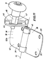
- Door 2 also includes in the production considered a mechanism 13 comprising a shaft 13a of axis D arranged towards the junction of rails 9 and 10 - and therefore towards the upper end of the rails 9-, two drums 13b cable winding mounted on the parts lateral ends of the shaft 13a towards the outside of the leaf 6 and between the latter and the side rails 9; of them cables linked on the one hand to the lower end panel of the leaf 6, on the other hand wound on the drums 13b; a or more elastic return members 13c mounted on the shaft 13a, such as a helical spring; ways to operation 13d, in this case manuals such as a handle controlling a latch cooperating with a window for hanging in the door frame 2.
- a mechanism 13 comprising a shaft 13a of axis D arranged towards the junction of rails 9 and 10 - and therefore towards the upper end of the rails 9-, two drums 13b cable winding mounted on the parts lateral ends of the shaft 13a towards the outside of the leaf 6 and between the latter and the side rail
- Cables are arranged vertically or substantially vertically between the side edges of leaf 6 and the rails 9. They are located in the immediate vicinity of the plane of opening 1. They pass between this plane and the supports of pebbles 11. They are therefore not accessible in a non desired.
- the panels 7 include an end panel lower 7a, an upper end panel 7b and a or several intermediate panels 7c.
- the leaf 6 comprises in all four identical panels 7.
- the panels 7 have a general outline in front elevation rectangular, the long side being horizontal and direction D and the small vertical side (when door 2 is installed and closed).
- a panel 7 is limited by the two side edges 12 and two longitudinal edges 14.
- the longitudinal edges 14 have, in cross section transverse, a generally pseudo-triangular profile.
- Two adjacent panels 7 are associated with pivoting relative to each other around an axis 15 parallel to direction D. They present two songs longitudinal substantially complementary to each other namely respectively a song called salient 14a (or male) and a song said to come in 14b (or female).
- the protruding edges 14a are, when door 2 is mounted and closed, directed towards up and in the up position. And, conversely, the songs returning 14b are directed downwards and in the low position.
- a panel 7 therefore comprises, at the top, a projecting edge 14a and, at the bottom, an inside song 14b.
- the protruding edge 14a has a general shape to concavity turned towards the inside of the panel 7.
- the edge reentrant 14b has a general shape with convexity facing the inside of the panel 7.
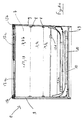
- a panel 7 includes first and second facings respectively 16 and 17, defining its large faces visible exterior 18 and 19, which are parallel.
- the facings 16 and 17 are made from sheets thin metal, rigidly secured one to the other.
- facings 16 and 17 are made from steel sheets with a thickness of about 0.4 mm.
- the two facings 16 and 17 are, in this embodiment, made from the same type of thin sheet.
- the two facings 16 and 17 are made from different types of leaves.
- the sheets of facings 16 and 17 can be made in other materials than steel, since this material is suitable for the use and performance required.
- the first facing 16 is that located on the outside of construction, that is to say towards the "noble" visible face 18 of door 2.
- the second facing 17 clearly visible on the Figure 1, is located on the inside of the building (face 19).
- At least one of the facings - in this case the first facing 16- has at least one rib of stiffening 20 recessed, longitudinal, extending between the two songs 12.
- the other facing, 17, is in this realization without such groove and is substantially plan.
- the longitudinal rib 20 extends entirely over the distance between the two edges 12. According to another embodiment, the rib 20 extends over only a part of this distance.
- the longitudinal rib 20 a in cross section transverse, a substantially triangular profile or round.
- the facing 16 comprises, in the embodiment shown corresponding to a panel 7 of appreciable width, several longitudinal ribs 20. These are of identical or close profile.
- the ribs 20 are located essentially in the middle area of panel 7, at the distance between the edges 14. They are spread so that less substantially equidistant from each other. In the considered realization where door 2 includes four panels 7, each of which includes five ribs longitudinal 20.
- the internal space 56 of the panel 7, closed at the periphery by the two facings 16, 17, is filled -at least partially- of a synthetic material which expands manufacturing.
- the panel 7 is devoid of reinforcement or interior insert of substantial stiffening.
- a longitudinal edge 14 has a thickness ranging from decreasing, continuously, from the large faces 18, 19 to its longitudinal free edge 21.
- Edge 14 is essentially defined by several faces substantially successive planes of one of the facings, in the occurrence the outer facing 16 having the longitudinal ribs 20.
- edge 14 is defined by at most four faces (two faces in the embodiment shown), and a rounding forming the longitudinal free edge 21.
- these two faces are, from of the first large outer face 18 and as regards the facing 16, a face 22 of greater width followed a face 23 of smaller width, the latter being itself followed and terminated by the rounding of edge 21 of connection with the second large inner face 19.
- these two faces are, from of the first large outer face 18 and as regards the facing 16, by means of the rounded edge 21, a face 24 of smaller width and one side 25 of greater width of connection with the second large inner face 19.
- the facing 16 is folded and rolled in order to achieve the faces 22, 23, 24, 25 and the rounded edges 21.
- At least one face 26 of the rib 20 a relative to the first large outer face 18 of the facing 16, in the considered embodiment, an analogous or similar inclination from that of the face 22 of the protruding longitudinal edge 14a.
- the profile of the rib 20 is similar to or close to the profile formed by the two adjacent longitudinal edges of the two panels 7 associated and coplanar adjacent. This last profile is in the occurrence formed by a part of the face 22 of one of the panels 7 and the rounding 21 opposite the other panel 7.
- a panel 7 has a total thickness of less than 3 cm.
- the total mass of a panel 7 according to the structure described can be of the order of 9 to 10 kg / m 2 , in particular close to 9.5 kg / m 2 .
- the facing 16 is provided with longitudinal ribs 20 and also provided with at least one - and if necessary several - transverse ribs in hollow, similar in profile or close to that of a rib longitudinal 20, the panel being of the so-called cassette type.
- cassettes are typically stamped patterns on the exterior facing, forming shape reliefs rectangular or asymmetrical, with a slight hollow on the inner surface and surrounded by a border peripheral.
- the depth of a rib longitudinal 20 is of the order of magnitude of a third of the total thickness of the panel 7.
- the two sheets forming the facings 16 and 17 are rigidly secured to each other towards each of the edges 14 by folding with nesting 27.
- This folding 27 is flat and substantially coplanar with a large faces of the panel 7 in this case the second large inner face 19, on the side of the facing 17. In this embodiment, the folding 27 is therefore located on the side opposite to (i.e. opposite) the first large face 18 where the longitudinal rib (s) 20 is located.
- Folding 27 is obtained by means of a fold 28 in one direction of facing 16 and of a fold 29 in the other direction of facing 17, the two folds 28, 29 being nested one inside the other in the manner of a hook ( Figures 5a, 5b, 6a, 6b).
- the folding 27 is located with regard to the projecting edge 14a substantially opposite the edge 30 formed by the first inclined face 22 of the edge on the first large face opposite 18. With regard to the inside edge 14b, the folding 27 is located near the edge 31 formed by the first inclined face 25 of the edge on the same second large face 19.
- a folding 27 also forms a functional means of fixing of a hinge element of the pivoting means 8. Indeed, a folding 27 allows effective clamping of a (or more) screws 32 for hinge fixing.
- the facing 16 has a general U-shaped bowl, while the facing 17 is substantially flat.
- the panel 7 also comprises, fixed to each of its edges 12, an added U-shaped profile 33.
- a song 14 includes a face 22, 24 inclined between 15 ° and 25 °, in particular about 20 ° with respect to the large faces 18, 19. It also has a face 23, 25 inclined between 40 ° and 50 ° in particular about 45 ° on these same large faces 18, 19.
- Two adjacent faces of a song 14, namely 22, 23 of a part 24, 25 on the other hand form an edge between them and a salient or re-entrant angle respectively 34, 35, between 150 ° and 160 °, in particular about 155 °.
- the rounding 21 has a radius of curvature of the order or less than a tenth of the total thickness of the panel 7.
- the pivot means 8 comprise at least two hinges end 8a towards the side edges 12 and, if applicable if necessary, one or more intermediate hinges 8b.
- the two elements 36, 37 of each hinge 8 are fixed to the panels 7 at least on folds with nesting 27. These elements include platinum-shaped parts 38 provided with holes 39 for the screws 32 of the shoulder head type and curved parts 40 for passage and fixing a pin 41 forming the axis 15.
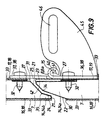
- the pivot axis 15 of the hinges 8, therefore of the panels 7, is situated outside the space taken up by the panels, near the second large face 19 and the facing 17 where the folding 27 is located, substantially at the right of the middle part of the protruding edge 14a of the first panel 7 and substantially to the right of the free edge 21 of the inside edge 14b of the second panel when it extends the first in a coplanar fashion.
- the panel 7 described as "first” is in the lower position and the one described as "second" is in the upper position.
- pivot axis 15 is spaced from the second large face 19 and the facing 17 of the first panel 7 worth about a third of the magnitude, half, or even less, of the total thickness of the panel 7.
- the two longitudinal edges 14a, 14b opposite the two panels 7 are spaced from each other by a free space 42, reduced.
- This space 42 thus configured and proportioned forms an external finger clip.
- the faces 24, 25 of the re-entrant edge 14b are substantially tangents to an arc having the axis of pivot 15.
- the end hinges 8a are fixed to the profiles reported 33 forming the side edges 12.
- door 2 also includes an anti inner finger clip 43 in the form of plates or added profiles, fixed flat on the second panel 7, on the second large face 19 where the folding 27 is located (facing 17).
- an anti inner finger clip 43 in the form of plates or added profiles, fixed flat on the second panel 7, on the second large face 19 where the folding 27 is located (facing 17).
- Such a plate or section 43 extends until it is slightly below the pivot axis 15, when the two panels in question are in extension relative to each other in a coplanar fashion.
- the plate or profile 43 is folded at 44 to come against the facing 16 of the first panel when the two panels are in overtime and co-planar.
- the internal anti-finger clip 43 is not an insert fixed flat on the large side 19 of the second panel 7, but is integrated into side 19 of the facing 17.
- the large face 19 then extends to be slightly offset from the middle of the edge protruding 14a from the first panel 7, when the two panels in question are an extension of one to the other in a coplanar fashion (Figure 7a).
- the large face 19 is folded at 44 to come against the facing 16 of the first panel 7 when the two panels are in extension and coplanar, and to form the folding 27 for the second panel 7.
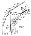
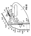
- One of the two elements of an end hinge 8a namely element 36 for example, has a square shape having on the one hand the plate 38 and on the other hand a tab 45 provided with an oblong lumen 46, extending substantially perpendicular to the plate 38 in question, in which is rigidly fixed but adjustable in position a pin 47 supporting the roller 11.
- the said pin 47 has in cross section a profile 48 non-circular, in particular polygonal, for clamping fixation.
- the panels 7 thus formed have the advantage of being of a reduced weight. So it is the same for the whole leaf 6.
- This structure results in the drum cable winding can be reduced in diameter, such as between 65 and 75 mm.
- the lintel fallout and the corner pieces can also be reduced in size, as it has been indicated previously.
- the door further comprises a lock, for example a reminder automatic, two control rods with end caps ends which come to lock in strikes fixed.
- a lock for example a reminder automatic, two control rods with end caps ends which come to lock in strikes fixed.
- the lock is operated by a handle locked by a key cylinder.
- a pre-assembly allows two sets to be made.
- a first set includes the lateral guide rails 9, the leaf 6 placed between them, the rollers 11 cooperating with the rails 9 and, finally, the mechanism 13.
- a second set includes upper guide rails 10, optionally a cross member 49 intended to connect them.
- the first set 6, 7, 9, 11, 13 is compact and fits in a generally shaped envelope flattened parallelepiped. Indeed, as has been previously mentioned, this set is limited laterally by the rails 9, the drums 13b not projecting not of this set since placed between leaf 6 and the rails 9. As for the cables, they are incorporated in the door 2 hardware, i.e. they are not projecting.
- the first set of door 2 which has just been described is such that it can also be preset during the manufacturing. This pre-setting concerns the length, arrangement and tension of cables as well as springs 13c.
- This constructive arrangement is advantageous because it leads to a quality pre-setting during manufacturing and avoids tedious, long or delicate operations at the final installation site of the door.
- the second set 10, 49 can be placed flat against the leaf 6 of the first assembly on the side of the second large face 19.
- the two sets which have just been described do they form a package that can fit into a thickness overall less than 125 mm, while in the condition of the technical thickness is close to and even exceeds 155 mm.
- Doors 2 as just described are conditioned by a package 50.
- the packaging 50 comprises a support 51 forming a pallet for its part 52 and a rack for its part 53.
- the rack 53 is suitable for receiving a plurality of doors as just described, placed side by side side.
- the support 51 includes, for the rack portion 53 two lateral flanks 54. Furthermore, the packaging 50 also comprises, in the embodiment considered, two side flat irons 55.
- Such packaging can receive up to nine doors each in the form of a package previously described. These doors are placed two by two symmetrical way that the first two large faces 18 or both second large faces 19 of the two doors are facing each other from each other, or placed in the same direction.
- the doors being thus arranged, they can be fixed removably by their side rails 9 to the sides 54 by means of screws.
- the support 51 is placed in the lower part, forming a pallet.
- the flat irons 55 are placed in the upper part.
- the overall size of such packaging comprising nine doors and part of a parallelepiped is for example 1.15 mx 3.20 m by 2.60 m in height, or less.
- the doors once manufactured are conditioned as well that it has just been described. This conditioning is easily transportable given the limited weight of panels 7.
- Packaging 50 allows storage convenient waiting of doors before they are put in place in a construction.
- the door having been pre-assembled in manufacturing and pre-adjusted, mounting can be quick.
Landscapes
- Engineering & Computer Science (AREA)
- Civil Engineering (AREA)
- Structural Engineering (AREA)
- Securing Of Glass Panes Or The Like (AREA)
- Refrigerator Housings (AREA)
- Passenger Equipment (AREA)
- Body Structure For Vehicles (AREA)
- Elevator Door Apparatuses (AREA)
- Wing Frames And Configurations (AREA)
- Automobile Manufacture Line, Endless Track Vehicle, Trailer (AREA)
- Window Of Vehicle (AREA)
- Lock And Its Accessories (AREA)
Abstract
Description
L'invention est relative aux portes sectionnelles à effacement au plafond et débattement vertical telles que des portes de garage.The invention relates to sectional doors with ceiling erasure and vertical travel such as garage doors.
Elle concerne plus particulièrement une porte une fois fabriquée, pré-montée et pré-réglée d'une part, une fois mise en place dans la construction à laquelle elle est destinée d'autre part ; un conditionnement incorporant plusieurs portes pré-montées ; et enfin un procédé de montage d'une telle porte.It relates more particularly to a door once manufactured, pre-assembled and pre-adjusted on the one hand, once set up in the building to which it is on the other hand; packaging incorporating several pre-assembled doors; and finally a method of mounting a such door.
On connaít déjà des portes sectionnelles à effacement au plafond et débattement vertical telles que des portes de garage.We already know sectional doors erasing at ceiling and vertical travel such as garage.
Une structure générale connue de telles portes est décrite notamment dans les documents EP-A-666 401, WO-A-96/36 784, EP-A-230 499, US-A-3 311 159, FR-A-2 304 756, FR-A-2 244 068, US-A-2 083 467, US-A-3 160 200 et US-A-4 472 910, US-4 878 529.A known general structure of such doors is described in particular in documents EP-A-666 401, WO-A-96/36 784, EP-A-230 499, US-A-3 311 159, FR-A-2 304 756, FR-A-2 244 068, US-A-2 083 467, US-A-3 160 200 and US-A-4 472 910, US-4 878 529.
Les documents EP-A-304 642, EP-A-370 324 et EP-A-370 376 s'intéressent à la structure des chants longitudinaux de deux panneaux adjacents.Documents EP-A-304 642, EP-A-370 324 and EP-A-370 376 are interested in the structure of the longitudinal edges of two adjacent panels.
Les portes de garage considérées sont destinées à être mises en place dans une construction comprenant une ouverture que la porte est destinée à occulter. Les dimensions hors tout de la porte (largeur horizontale et hauteur verticale) sont à cet effet plus grandes que les dimensions de l'ouverture en question.The garage doors considered are intended to be implemented in a construction comprising a opening that the door is intended to obscure. The overall dimensions of the door (horizontal width and vertical height) are larger than the dimensions of the opening in question.
La construction comprend généralement un plafond et deux cloisons de part et d'autre de l'ouverture définissant une retombée de linteau et des écoinçons droit et gauche respectivement de dimensions appréciables. Construction usually includes a ceiling and two partitions on either side of the opening defining a fall of the lintel and the right and left corner pieces respectively of appreciable dimensions.
La retombée de linteau est nécessaire par suite de la présence, à cet endroit, de rails, d'un arbre supportant des tambours d'enroulement de câbles, d'un ou plusieurs organes de rappel du vantail. Quant aux écoinçons, ils sont nécessaires pour le logement de tourillons porte galets, de galets et de rails latéraux.The lintel fallout is necessary due to the presence, at this point, of rails, of a tree supporting cable winding drums, of one or more leaf return members. As for the corner pieces, they are necessary for the housing of roller bearing pins, rollers and side rails.
Les portes connues précédemment considérées sont stockées livrées et fournies en plusieurs pièces détachées. Le constructeur doit assembler ces pièces sur le site et assurer le réglage. Ces opérations sont forcément longues, coûteuses, et nécessitent souvent l'intervention d'un professionnel spécialiste du montage. De plus, le réglage peut se révéler n'être pas optimal.Known doors previously considered are stored delivered and supplied in several spare parts. The manufacturer must assemble these parts on site and ensure adjustment. These operations are necessarily long, expensive, and often require the intervention of a professional assembly specialist. In addition, the setting may turn out to be less than optimal.
L'invention a notamment pour but de limiter la hauteur de la retombée de linteau et la largeur des écoinçons, ainsi que les durées d'assemblage et réglage sur le site de la construction.The object of the invention is in particular to limit the height of the lintel fallout and the width of the corner pieces, as well that the assembly and adjustment times on the site of the construction.
En conséquence, pour une ouverture donnée, il est possible d'utiliser une porte plus petite que celles antérieures. Ou, inversement, pour une porte donnée, l'ouverture peut être plus grande. Par ailleurs, le stockage, la livraison, la fourniture et l'installation (assemblage, montage, réglage) sont facilités, plus courts en durée, plus compacts en volume, moins coûteux.Consequently, for a given opening, it is possible to use a door smaller than the previous ones. Or, conversely, for a given door, the opening can to be bigger. In addition, storage, delivery, supply and installation (assembly, mounting, adjustment) are easier, shorter in duration, more compact in volume, less expensive.
L'invention a également pour but une porte qui ne présente pas les inconvénients de celles actuellement connues, qui soit simple tout en étant solide et facile à mettre en oeuvre.The object of the invention is also a door which does not have not the disadvantages of those currently known, which be simple while being solid and easy to set up artwork.
Selon un premier aspect, l'invention concerne une porte sectionnelle (2) à effacement au plafond et débattement vertical, telle que typiquement une porte de garage, comprenant :
- des rails de guidage latéraux disposés verticalement lorsque la porte est montée en situation, dits rails latéraux verticaux ;
- des rails de guidage supérieur, dits rails latéraux horizontaux, prolongeant les rails latéraux verticaux lorsque la porte est montée en situation;
- un vantail comprenant une succession de panneaux et supportant des galets, chaque panneau pouvant être monté à pivotement sur au moins un autre panneau analogue, autour d'un axe parallèle à une direction longitudinale normalement horizontale lorsque la porte est montée en situation, chaque panneau, mince et léger, comprenant un premier et un second parements réalisés à partir de feuilles minces en métal ou matériau analogue, l'espace fermé à la périphérie par les deux parements étant au moins partiellement rempli d'une matière synthétique expansée à la fabrication ; les galets étant destinés à coopérer avec les rails latéraux verticaux et horizontaux afin de guider convenablement le vantail ;
- un arbre disposé longitudinalement vers une extrémité des rails de guidage latéraux verticaux ;
- un ou deux tambours d'enroulement de câbles montés calés sur les parties extrêmes de l'arbre vers l'extérieur du vantail et entre le vantail et les rails latéraux ;
- un ou deux câbles liés d'une part au vantail au panneau d'extrémité inférieure, d'autre part enroulés sur le ou les tambours, ces câbles n'étant pas ainsi accessibles de façon non souhaitée ;
- un ou plusieurs organes élastiques de rappel pré-tendus montés sur l'arbre, tels que ressort hélicoïdal ;
- des moyens de manoeuvre du vantail manuels et/ou motorisés ;
- un premier ensemble formant un ensemble prémonté et préréglé avant l'installation sur le site et incluant : les rails de guidage latéraux verticaux, le vantail, l'arbre, le ou les tambours d'enroulement de câbles, le ou les câbles, le ou les organes élastiques de rappel, les moyens de manoeuvre du vantail manuels et/ou motorisés ;
- un second ensemble incluant les rails horizontaux de guidage supérieur.
- lateral guide rails arranged vertically when the door is mounted in situation, called vertical lateral rails;
- upper guide rails, called horizontal side rails, extending the vertical side rails when the door is mounted in position;
- a leaf comprising a succession of panels and supporting rollers, each panel being able to be pivotally mounted on at least one other similar panel, around an axis parallel to a normally horizontal longitudinal direction when the door is mounted in position, each panel, thin and light, comprising first and second facings made from thin sheets of metal or similar material, the space closed at the periphery by the two facings being at least partially filled with a synthetic material expanded during manufacture; the rollers being intended to cooperate with the vertical and horizontal lateral rails in order to properly guide the leaf;
- a shaft disposed longitudinally towards one end of the vertical lateral guide rails;
- one or two cable winding drums mounted wedged on the end parts of the shaft towards the outside of the leaf and between the leaf and the side rails;
- one or two cables linked on the one hand to the leaf to the lower end panel, on the other hand wound on the drum or drums, these cables not being thus undesirably accessible;
- one or more elastic pre-tensioned return members mounted on the shaft, such as a helical spring;
- manual and / or motorized leaf maneuvering means;
- a first assembly forming a pre-assembled and preset assembly before installation on site and including: the vertical lateral guide rails, the leaf, the shaft, the cable winding drum (s), the cable (s), the or the elastic return members, the manual and / or motorized leaf operating means;
- a second assembly including the horizontal upper guide rails.
La masse de chaque panneau mince et léger du vantail est de l'ordre de 9 à 10 Kg/m2, notamment voisine de 9.5 Kg/m2.The mass of each thin and light panel of the leaf is around 9 to 10 Kg / m2, in particular around 9.5 Kg / m2.
L'épaisseur totale de chaque panneau mince et léger du vantail est inférieure à 3 cm.The total thickness of each thin and light panel of the leaf is less than 3 cm.
Selon une réalisation, le second ensemble comprend une traverse destinée à raccorder les rails de guidage supérieur lorsque la porte est montée en situation.According to one embodiment, the second set includes a crosspiece for connecting the guide rails higher when the door is mounted in situation.
Selon une autre caractéristique, le second ensemble est placé à plat contre le vantail du premier ensemble, les deux ensembles formant un colis.According to another characteristic, the second set is placed flat against the leaf of the first set, the two sets forming a package.
Selon un second aspect, l'invention concerne un conditionnement incorporant plusieurs portes sectionnelles à effacement au plafond et débattement vertical telles que décrites précédemment, comportant un support formant palette et ratelier et recevant une pluralité de portes placées côte à côte, et comprenant en autre une pluralité de premiers ensembles prémontés préréglés, chaque premier ensemble supportant en outre les deux rails de guidage supérieur logés tête-bêche à l'intérieur du premier ensemble.According to a second aspect, the invention relates to a packaging incorporating several sectional erasing doors ceiling and vertical travel as described previously, comprising a pallet support and rack and receiving a plurality of doors placed side by side, and further comprising a plurality of first pre-set pre-set, each first assembly further supporting the two guide rails upper housed upside down inside the first together.
Le support comprend deux flancs latéraux auxquels sont fixés de façon amovible les rails de guidage latéraux et le cas échéant :
- deux fers plats auxquels sont fixés de façon amovible les rails de guidage latéraux à l'opposé des flancs
- et/ou un profil métallique fixé de façon amovible sous les rails de guidage latéraux permettant de protéger chaque porte pendant le transport et de maintenir l'écartement entre les deux flancs latéraux.
- two flat bars to which the lateral guide rails opposite the sides are removably attached
- and / or a metal profile removably fixed under the lateral guide rails making it possible to protect each door during transport and to maintain the spacing between the two lateral flanks.
Ce conditionnement peut contenir jusqu'à neuf portes.This package can contain up to nine doors.
Selon un troisième aspect, l'invention concerne un procédé de mise en place, dans une construction pourvue d'une ouverture, d'une porte à effacement au plafond et débattement vertical, ladite porte ayant été fabriquée, pré-montée et pré-réglée, le cas échéant conditionnée comme indiqué précédemment, dans lequel l'on amène la porte fabriquée, pré-montée et pré-réglée sur le site de la construction et l'on met en place et l'on fixe à ladite construction le premier et le second ensembles.According to a third aspect, the invention relates to a method of implementation, in a construction provided with a opening, an erasing door on the ceiling and vertical travel, said door having been manufactured, pre-assembled and pre-adjusted, if necessary conditioned as previously indicated, in which the door is brought manufactured, pre-assembled and pre-set on the site of the construction and we set up and fix it to said construction of the first and second sets.
Selon un quatrième aspect l'invention concerne une porte sectionnelle à effacement au plafond et débattement vertical telle que typiquement une porte de garage, destinée à être montée dans l'ouverture d'une construction, comprenant :
- des rails de guidage latéraux et des rails de guidage supérieurs;
- un vantail comprenant une succession de panneaux et supportant des galets, chaque panneau pouvant être monté à pivotement sur au moins un autre panneau analogue, autour d'un axe parallèle à une direction longitudinale normalement horizontale lorsque la porte est montée en situation, chaque panneau, mince et léger, comprenant un premier et un second parements réalisés à partir de feuilles minces en métal ou matériau analogue, l'espace fermé à la périphérie par les deux parements étant au moins partiellement rempli d'une matière synthétique expansée à la fabrication ; les galets étant destinés à coopérer avec les rails latéraux et supérieurs afin de guider convenablement la vantail ;
- un arbre disposé longitudinalement vers la jonction des rails latéraux et des rails supérieurs ;
- un ou deux tambours d'enroulement de câbles montés sur les parties extrêmes de l'arbre vers l'extérieur du vantail et entre celui-ci et les rails latéraux ;
- un ou deux câbles liés d'une part au vantail au panneau d'extrémité inférieure, d'autre part enroulés sur le ou les tambours ;
- un ou plusieurs organes élastiques de rappel montés sur l'arbre, tels que ressort hélicoïdal ;
- et des moyens de manoeuvre manuels et/ou motorisés la porte étant constituée par :
- un premier ensemble tel que décrit précédemment fixé à la construction à l'aide de moyens de fixation ;
- un second ensemble comportant des rails de guidage supérieur tels que décrits précédemment.
- lateral guide rails and upper guide rails;
- a leaf comprising a succession of panels and supporting rollers, each panel being able to be pivotally mounted on at least one other similar panel, around an axis parallel to a normally horizontal longitudinal direction when the door is mounted in position, each panel, thin and light, comprising first and second facings made from thin sheets of metal or similar material, the space closed at the periphery by the two facings being at least partially filled with a synthetic material expanded during manufacture; the rollers being intended to cooperate with the lateral and upper rails in order to properly guide the leaf;
- a shaft disposed longitudinally towards the junction of the side rails and the top rails;
- one or two cable winding drums mounted on the end parts of the shaft towards the outside of the leaf and between the latter and the side rails;
- one or two cables linked on the one hand to the leaf to the lower end panel, on the other hand wound on the drum or drums;
- one or more elastic return members mounted on the shaft, such as a helical spring;
- and manual and / or motorized operating means, the door being constituted by:
- a first assembly as described above fixed to the construction by means of fixing means;
- a second assembly comprising upper guide rails as described above.
Grâce à l'allègement du poids du vantail, il est possible d'avoir des tambours de diamètre réduit, tel que compris entre 65 et 75 mm.Thanks to the lighter weight of the leaf, it is possible to have drums of reduced diameter, as understood between 65 and 75 mm.
Une construction comprend une ouverture dans laquelle est montée une porte telle qu'elle vient d'être décrite. La construction est telle que les retombées de linteau et les écoinçons sont de taille réduite pouvant être inférieure à 10 cm, notamment respectivement de l'ordre de 8 cm et de l'ordre de 9 cm.A construction includes an opening in which is mounted a door as just described. The construction is such that the fallout of the lintel and the corner pieces are reduced in size which can be less than 10 cm, in particular of the order of 8 cm and around 9 cm.
Dans la construction considérée, les rails de guidage supérieurs ainsi que les charnières sont situés du côté intérieur et les nervures longitudinales du côté extérieur.In the construction under consideration, the guide rails the hinges are located on the side inside and the longitudinal ribs on the outside.
L'invention sera bien comprise grâce à la description qui suivra en référence aux dessins annexés dans lesquels :
- la figure 1 est une vue schématique en perspective du côté intérieur d'une construction comportant une porte selon l'invention, représentée fermée ;
- la figure 2 est une vue en élévation du vantail de la porte de la figure 1, à plus grande échelle, vu du côté intérieur ;
- la figure 3 est une vue en élévation d'un panneau du vantail de la figure 2, à plus grande échelle, vu du côté extérieur ;
- la figure 4 est une vue schématique en coupe transversale du panneau de la figure 3 selon la ligne IV-IV ;
- les figures 5a et 5b sont deux vues schématiques en coupe transversale des deux parements, respectivement extérieur et intérieur d'un panneau ;
- les figures 6a et 6b sont deux vues schématiques partielles, à plus grande échelle, des figures 5a et 5b montrant les pliages des parements ;
- la figure 7 est une vue schématique, partielle, en coupe par un plan vertical, à plus grande échelle, de deux panneaux coplanaires, illustrant plus spécialement leurs chants longitudinaux ; la figure 7 a est une vue analogue selon une variante de réalisation ;
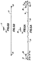
- la figure 8 est une vue analogue à celle de la figure 7, les deux panneaux étant ici dans leur position relative extrême pivotée -non coplanaires- correspondant à la porte ouverte ;
- les figures 9 et 10 sont deux vues schématiques
similaires aux figures 7
et 8 représentant les panneaux avec les charnières d'extrémité ; - la figure 11 est une vue en perspective représentant une charnière d'extrémité avec son tourillon et son galet ;
- la figure 12 est une vue de face d'un conditionnement de porte selon l'invention ;
- la figure 13 est une vue de côté du conditionnement de la figure 12.
- la figure 14 est une vue de face d'une porte pré-montée comprenant deux ensembles formant un colis.
- Figure 1 is a schematic perspective view of the interior side of a construction comprising a door according to the invention, shown closed;
- Figure 2 is an elevational view of the door leaf of Figure 1, on a larger scale, seen from the inside;
- Figure 3 is an elevational view of a panel of the leaf of Figure 2, on a larger scale, seen from the outside;
- Figure 4 is a schematic cross-sectional view of the panel of Figure 3 along the line IV-IV;
- Figures 5a and 5b are two schematic cross-sectional views of the two facings, respectively exterior and interior of a panel;
- Figures 6a and 6b are two partial schematic views, on a larger scale, of Figures 5a and 5b showing the folds of the facings;
- Figure 7 is a schematic partial view in section through a vertical plane, on a larger scale, of two coplanar panels, illustrating more particularly their longitudinal edges; Figure 7a is a similar view according to an alternative embodiment;
- Figure 8 is a view similar to that of Figure 7, the two panels here being in their extreme pivoted relative position - not coplanar - corresponding to the open door;
- Figures 9 and 10 are two schematic views similar to Figures 7 and 8 showing the panels with the end hinges;
- Figure 11 is a perspective view showing an end hinge with its pin and its roller;
- Figure 12 is a front view of a door package according to the invention;
- FIG. 13 is a side view of the packaging of FIG. 12.
- Figure 14 is a front view of a pre-mounted door comprising two assemblies forming a package.
Sur les figures est représentée une construction ayant une
ouverture 1 à laquelle est destinée une porte 2. In the figures is shown a construction having a
opening 1 for which a
L'ouverture 1 est typiquement celle permettant le passage
d'un véhicule automobile, la porte 2 étant donc une porte
de garage.The opening 1 is typically that allowing passage
of a motor vehicle,
On désigne par 3 le sol, par 4 la retombée de linteau et par 5 les écoinçons, d'un côté et de l'autre.We denote by 3 the ground, by 4 the fall of the lintel and by 5 the corner pieces, on one side and on the other.
Selon les dispositions constructives envisagées, la
retombée de linteau 4 et les écoinçons 5 sont de taille
réduite, comparativement à celles de l'état de la
technique.According to the constructive provisions envisaged, the
Par exemple, dans une réalisation, les tailles sont inférieures à 10 cm et notamment de l'ordre de 8 cm pour la retombée de linteau et de l'ordre de 9 cm pour chaque écoinçon.For example, in one embodiment, the sizes are less than 10 cm and in particular of the order of 8 cm for the lintel fallout and about 9 cm for each corner.
La porte 2 comprend un vantail 6, mobile entre une position
de fermeture (figure 1) et une position d'ouverture.
En position de fermeture, le vantail 6 est disposé
verticalement ou sensiblement verticalement dans
l'ouverture 1.In the closed position, the
En position d'ouverture, le vantail 6 est disposé
horizontalement ou sensiblement horizontalement vers le
plafond attenant à la retombée de linteau 4.In the open position, the
La porte 2 considérée est donc de type à effacement au
plafond et débattement vertical. Elle est par ailleurs de
type sectionnelle, le vantail 6 comprenant une succession
de panneaux 7 semblables ou identiques entre eux. Deux
panneaux adjacents sont agencés et montés l'un sur l'autre
d'une manière à être associés l'un à l'autre par des moyens
de pivotement 8.The
La porte 2 comprend également des rails de guidage latéraux
9 et des rails de guidage supérieurs 10. Ces rails sont
disposés respectivement verticalement ou sensiblement
verticalement, horizontalement ou sensiblement
horizontalement. Ils sont placés à l'intérieur de la
construction, respectivement de part et d'autre et au-dessus
de l'ouverture 1. Ils sont localisés à proximité de
cette ouverture 1. Les rails 9 et 10 forment deux ensembles
d'un côté et de l'autre de l'ouverture 1. Chacun de ces
deux ensembles comporte un ou deux rails latéraux 9 et un
ou deux rails supérieurs 10, les derniers adjacents aux
parties extrêmes supérieures des rails latéraux 9. Les deux
ensembles de rails 9 et 10 sont situés dans deux plans
verticaux parallèles entre eux, perpendiculaires au plan de
l'ouverture 1. Les rails 9 sont fixés, directement ou non à
la paroi de la construction dans laquelle est ménagée
l'ouverture 1. Les rails 10 sont fixés notamment au
plafond.
On définit par D une direction horizontale située dans le
plan de l'ouverture 1, perpendiculaire au plan des deux
ensembles de rails 9 et 10.We define by D a horizontal direction located in the
plane of opening 1, perpendicular to the plane of the two
Des galets 11 d'axe D coopérant avec les rails 9 et 10 sont
portés par les panneaux 7 en saillie de leurs chants
latéraux verticaux 12. Les galets 11 peuvent coulisser dans
les rails 9 et 10 pour permettre le déplacement du vantail
6 entre ses positions d'ouverture et de fermeture.
La porte 2 comprend également dans la réalisation
considérée un mécanisme 13 comportant un arbre 13a d'axe D
disposé vers la jonction des rails 9 et 10 -et donc vers
l'extrémité supérieure des rails 9-, deux tambours 13b
d'enroulement de câbles montés calés sur les parties
extrêmes latérales de l'arbre 13a vers l'extérieur du
vantail 6 et entre celui-ci et les rails latéraux 9 ; deux
câbles liés d'une part au panneau d'extrémité inférieure du
vantail 6, d'autre part enroulés sur les tambours 13b ; un
ou plusieurs organes élastiques de rappel 13c montés sur
l'arbre 13a, tels que ressort hélicoïdal ; des moyens de
manoeuvre 13d, en l'occurrence manuels tels qu'une poignée
commandant un loquet coopérant avec une fenêtre
d'accrochage ménagée dans le dormant de la porte 2.
Les câbles sont disposés verticalement ou sensiblement
verticalement entre les bords latéraux du vantail 6 et les
rails 9. Ils sont situés à proximité immédiate du plan de
l'ouverture 1. Ils passent entre ce plan et les supports de
galets 11. Ils ne sont donc pas accessibles de façon non
souhaitée.Cables are arranged vertically or substantially
vertically between the side edges of
Les panneaux 7 comprennent un panneau d'extrémité
inférieure 7a, un panneau d'extrémité supérieure 7b et un
ou plusieurs panneaux intermédiaires 7c. Dans la
réalisation de la figure 1, le vantail 6 comporte en tout
quatre panneaux 7, identiques.The
Les panneaux 7 ont en élévation frontale un contour général
rectangulaire, le grand côté étant horizontal et de
direction D et le petit côté vertical (lorsque la porte 2
est installée et fermée).The
Un panneau 7 est limité par les deux chants latéraux 12 et
deux chants longitudinaux 14.A
Le cas échéant, il est associé aux chants longitudinaux 14
libres des panneaux 7a et 7b un joint d'étanchéité, une
barre palpeuse ou autre dispositif approprié.If necessary, it is associated with the
Les chants longitudinaux 14 ont, en section droite transversale, un profil de forme générale pseudo-triangulaire.The longitudinal edges 14 have, in cross section transverse, a generally pseudo-triangular profile.
Deux panneaux 7 adjacents sont associés à pivotement
relatif l'un par rapport à l'autre autour d'un axe 15
parallèle à la direction D. Ils présentent deux chants
longitudinaux sensiblement complémentaires l'un de l'autre
à savoir respectivement un chant dit saillant 14a (ou mâle)
et un chant dit rentrant 14b (ou femelle). Two
Dans la réalisation considérée, les chants saillants 14a
sont, lorsque la porte 2 est montée et fermée, dirigés vers
le haut et en position haute. Et, inversement, les chants
rentrant 14b sont dirigés vers le bas et en position basse.
Un panneau 7 comporte donc, en haut, un chant saillant 14a
et, en bas, un chant rentrant 14b.In the embodiment considered, the protruding
Le chant saillant 14a présente une forme générale à
concavité tournée vers l'intérieur du panneau 7. Le chant
rentrant 14b présente une forme générale à convexité
tournée vers l'intérieur du panneau 7.The protruding
On décrit par la suite les chants saillant 14a et rentrant
14b en se référant à l'association de deux panneaux 7 dans
laquelle ces chants sont conjugués.We describe below the protruding
Un panneau 7 comprend un premier et un second parements
respectivement 16 et 17, définissant ses grandes faces
extérieures visibles 18 et 19, lesquelles sont parallèles.
Les parements 16 et 17 sont réalisés à partir de feuilles
métalliques minces, solidarisées rigidement l'une à
l'autre. En particulier, les parements 16 et 17 sont
réalisés à partir de feuilles en acier d'épaisseur de
l'ordre de 0,4 mm.A
Les deux parements 16 et 17 sont, dans cette réalisation,
réalisés à partir d'un même type de feuille mince.The two
Selon les réalisations, les deux parements 16 et 17 sont
réalisés à partir de types différents de feuilles. Les
feuilles des parements 16 et 17 peuvent être réalisées en
d'autres matériaux que l'acier, dès lors que ce matériau
est approprié à l'usage et aux performances requises.Depending on the designs, the two
Le premier parement 16 est celui situé du côté extérieur de
la construction c'est-à-dire vers la face visible "noble"
18 de la porte 2. Le second parement 17 bien visible sur la
figure 1, est situé du côté intérieur de la construction
(face 19). The
L'un au moins des parements -en l'occurrence le premier
parement 16- comporte au moins une nervure de
rigidification 20 en creux, longitudinale, s'étendant entre
les deux chants 12. L'autre parement, 17, est dans cette
réalisation dépourvu de telle rainure et est
substantiellement plan. Dans la réalisation représentée, la
nervure longitudinale 20 s'étend en totalité sur la
distance entre les deux chants 12. Selon une autre
réalisation, la nervure 20 s'étend sur une partie seulement
de cette distance.At least one of the facings - in this case the first
facing 16- has at least one rib of
stiffening 20 recessed, longitudinal, extending between
the two
La nervure longitudinale 20 a, en section droite transversale, un profil sensiblement triangulaire ou arrondi.The longitudinal rib 20 a, in cross section transverse, a substantially triangular profile or round.
Le parement 16 comporte, dans la réalisation représentée
correspondant à un panneau 7 de largeur appréciable,
plusieurs nervures longitudinales 20. Celles-ci sont de
profil identique ou proche. Les nervures 20 sont situées
essentiellement dans la zone médiane du panneau 7, à
l'écart des chants 14. Elles sont écartées de façon au
moins sensiblement équidistante entre elles. Dans la
réalisation considérée où la porte 2 comprend quatre
panneaux 7, chacun de ceux-ci comprend cinq nervures
longitudinales 20.The facing 16 comprises, in the embodiment shown
corresponding to a
L'espace interne 56 du panneau 7, fermé à la périphérie par
les deux parements 16, 17, est rempli -au moins
partiellement- d'une matière synthétique qui s'expanse à la
fabrication.The
Par ailleurs, le panneau 7 est dépourvu de renfort ou
d'insert intérieur de rigidification substantielle.Furthermore, the
Un chant longitudinal 14 a une épaisseur allant en
décroissant, de façon continue, depuis les grandes faces
18, 19 jusqu'à son bord libre longitudinal 21. A
Le chant 14 est essentiellement défini par plusieurs faces
sensiblement planes successives d'un des parements, en
l'occurrence le parement extérieur 16 ayant la ou les
nervures longitudinales 20.
Plus spécialement, le chant 14 est défini par au plus
quatre faces (deux faces dans la réalisation représentée),
et un arrondi formant le bord libre longitudinal 21.More specifically,
Pour le chant saillant 14a, ces deux faces sont, à partir
de la première grande face extérieure 18 et s'agissant du
parement 16, une face 22 de plus grande largeur suivie
d'une face 23 de plus petite largeur, cette dernière étant
elle-même suivie et terminée par l'arrondi du bord 21 de
raccordement avec la seconde grande face intérieure 19.For the protruding
Pour le chant rentrant 14b, ces deux faces sont, à partir
de la première grande face extérieure 18 et s'agissant du
parement 16, moyennant l'arrondi du bord 21, une face 24 de
plus petite largeur et une face 25 de plus grande largeur
de raccordement avec la seconde grande face intérieure 19.For the
Le parement 16 est plié et roulé en vue de réaliser les
faces 22, 23, 24, 25 et les bords arrondis 21.The facing 16 is folded and rolled in order to achieve the
Au moins une face 26 de la nervure 20 a, par rapport à la
première grande face extérieure 18 du parement 16, dans la
réalisation considérée, une inclinaison analogue ou voisine
de celle de la face 22 du chant longitudinal saillant 14a.At least one
Par ailleurs, dans cette réalisation, le profil de la
nervure 20 est analogue ou voisin du profil formé par les
deux bords longitudinaux adjacents des deux panneaux 7
adjacents associés et coplanaires. Ce dernier profil est en
l'occurrence formé par une partie de la face 22 de l'un des
panneaux 7 et l'arrondi 21 en regard de l'autre panneau 7.Furthermore, in this embodiment, the profile of the
Un panneau 7 a une épaisseur totale inférieure à 3 cm. A
La masse totale d'un panneau 7 selon la structure décrite
peut être de l'ordre de 9 à 10 kg/m2, notamment voisine de
9,5 kg/m2.The total mass of a
Toutefois, malgré cette légèreté, la rigidité du panneau 7
à la flexion est excellente.However, despite this lightness, the rigidity of the
Ce résultat peut être atteint alors même que les parements
16 et 17 peuvent être dépourvus de nervure, rainure ou
saillie de rigidification substantielle s'étendant en
direction transversale.This result can be achieved even when the
Toutefois, il serait possible de prévoir une -ou de- telle(s) nervure(s), rainure(s) ou saillie(s) de rigidification transversale(s).However, it would be possible to provide a -or- such (s) rib (s), groove (s) or projection (s) of transverse stiffening (s).
Ainsi, il serait possible que le parement 16 soit pourvu de
nervures longitudinales 20 et pourvu également d'au moins
une -et le cas échéant plusieurs- nervures transversales en
creux, de profil analogue ou voisin de celui d'une nervure
longitudinale 20, le panneau étant de type dit à cassettes.
Ces cassettes sont typiquement des motifs emboutis sur le
parement extérieur, formant des reliefs de forme
rectangulaire ou asymétrique, présentant un léger creux sur
la surface intérieure et entourés d'une bordure
périphérique.Thus, it would be possible that the facing 16 is provided with
Selon une réalisation, la profondeur d'une nervure
longitudinale 20 est de l'ordre de grandeur du tiers de
l'épaisseur totale du panneau 7.According to one embodiment, the depth of a rib
longitudinal 20 is of the order of magnitude of a third of
the total thickness of the
Les deux feuilles formant les parements 16 et 17 sont
solidarisées rigidement l'une à l'autre vers chacun des
chants 14 par un pliage avec imbrication 27.The two sheets forming the
Ce pliage 27 est plat et sensiblement coplanaire avec une
des grandes faces du panneau 7 en l'occurrence la seconde
grande face intérieure 19, du côté du parement 17. Dans
cette réalisation, le pliage 27 est donc situé du côté
opposé à (c'est-à-dire en regard) la première grande face
18 où se trouve la ou les nervures longitudinales 20.This
Le pliage 27 est obtenu au moyen d'un pli 28 dans un sens
du parement 16 et d'un pli 29 dans l'autre sens du parement
17, les deux plis 28, 29 étant imbriqués l'un dans l'autre
à la manière d'un crochet (figures 5a, 5b, 6a, 6b).
Le pliage 27 est situé s'agissant du chant saillant 14a
sensiblement en regard de l'arête 30 que forme la première
face inclinée 22 du chant sur la première grande face
opposée 18. S'agissant du chant rentrant 14b, le pliage 27
est situé au voisinage de l'arête 31 que forme la première
face inclinée 25 du chant sur la même seconde grande face
19.The
Un pliage 27 forme également un moyen fonctionnel de
fixation d'un élément de charnière des moyens de pivotement
8. En effet, un pliage 27 permet le serrage efficace d'une
(ou plusieurs) vis 32 de fixation de charnière.A folding 27 also forms a functional means of
fixing of a hinge element of the pivoting means
8. Indeed, a
Avec la réalisation qui est décrite, le parement 16 présente une forme générale de cuvette en U, tandis que le parement 17 est sensiblement plat.With the embodiment which is described, the facing 16 has a general U-shaped bowl, while the facing 17 is substantially flat.
Le panneau 7 comporte également, fixé sur chacun de ses
chants 12, un profilé en U rapporté 33.The
Dans la réalisation considérée, un chant 14 comporte une
face 22, 24 inclinée entre 15° et 25°, en particulier
d'environ 20° par rapport aux grandes faces 18, 19. Il
comporte également une face 23, 25 inclinée entre 40° et
50° en particulier d'environ 45° sur ces mêmes grandes
faces 18, 19.In the embodiment considered, a
Deux faces adjacentes d'un chant 14 à savoir 22, 23 d'une
part 24, 25 d'autre part forment entre elles une arête et
un angle saillant ou rentrant respectivement 34, 35,
compris entre 150° et 160°, en particulier d'environ 155°. Two adjacent faces of a
Quant à l'arrondi 21, il a un rayon de courbure de l'ordre
ou inférieur au dixième de l'épaisseur totale du panneau 7.As for the rounding 21, it has a radius of curvature of the order
or less than a tenth of the total thickness of the
Deux panneaux 7 tels qu'ils viennent d'être décrits sont
montés l'un sur l'autre à pivotement relatif par les moyens
de pivotement 8 associés rigidement pour un des panneaux 7
vers son chant longitudinal saillant 14a et, pour l'autre
panneau 7, vers son chant longitudinal rentrant 14b. Cette
association rigide est assurée au moyen des vis 32. Les
moyens de pivotement 8 comprennent au moins deux charnières
d'extrémité 8a vers les chants latéraux 12 et, le cas
échéant, une ou plusieurs charnières intermédiaires 8b. Les
deux éléments 36, 37 de chaque charnière 8 sont fixés aux
panneaux 7 au moins sur les pliages avec imbrication 27.
Ces éléments comportent des parties en forme de platine 38
pourvu de trous 39 pour les vis 32 de type à tête épaulée
et de parties incurvées 40 pour le passage et la fixation
d'un tourillon 41 formant l'axe 15.Two
L'axe de pivotement 15 des charnières 8, donc des panneaux
7, est situé à l'extérieur de l'encombrement des panneaux,
à proximité de la seconde grande face 19 et du parement 17
où se trouve le pliage 27, sensiblement au droit de la
partie médiane du chant saillant 14a du premier panneau 7
et sensiblement au droit du bord libre 21 du chant rentrant
14b du second panneau lorsque celui-ci prolonge le premier
de façon coplanaire. Sur les figures 7, 8, 9 et 10, le
panneau 7 qualifié de "premier" est en position inférieure
et celui qualifié de "second" est en position supérieure.The
Plus particulièrement, l'axe de pivotement 15 est écarté de
la seconde grande face 19 et du parement 17 du premier
panneau 7 d'une valeur de l'ordre de grandeur du tiers, de
la moitié, ou même moins, de l'épaisseur totale du panneau
7.More particularly, the
Les deux chants longitudinaux 14a, 14b en regard des deux
panneaux 7 sont écartés l'un de l'autre par un espace libre
42, réduit. Cet espace 42 ainsi configuré et proportionné
forme un anti pince doigt extérieur.The two
Les faces 24, 25 du chant rentrant 14b sont sensiblement
tangentes à un arc de cercle ayant pour centre l'axe de
pivotement 15.The faces 24, 25 of the
Les charnières d'extrémité 8a sont fixées sur les profilés rapportés 33 formant les chants latéraux 12.The end hinges 8a are fixed to the profiles reported 33 forming the side edges 12.
Selon une réalisation la porte 2 comprend également un anti
pince doigt intérieur 43 sous la forme de plaques ou
profilés rapportés, fixés à plat sur le second panneau 7,
sur la seconde grande face 19 où se trouve le pliage 27
(parement 17). Une telle plaque ou profilé 43 s'étend
jusqu'à être légèrement sous l'axe de pivotement 15,
lorsque les deux panneaux en question sont en prolongement
l'un par rapport à l'autre de façon coplanaire.According to one embodiment,
Dans une variante de cette réalisation (figure 7), la
plaque ou profilé 43 est repliée en 44 pour venir contre le
parement 16 du premier panneau lorsque les deux panneaux
sont en prolongation et coplanaires.In a variant of this embodiment (FIG. 7), the
plate or
Selon une autre réalisation, l'anti pince doigt intérieur
43 n'est pas une pièce rapportée fixée à plat sur la grande
face 19 du second panneau 7, mais est intégré à la face 19
du parement 17. La grande face 19 s'étend alors jusqu'à
être légèrement décalée de la partie médiane du chant
saillant 14a du premier panneau 7, lorsque les deux
panneaux en question sont en prolongement l'un par rapport
à l'autre de façon coplanaire (figure 7a).According to another embodiment, the internal
La grande face 19 est repliée en 44 pour venir contre le
parement 16 du premier panneau 7 lorsque les deux panneaux
sont en prolongation et coplanaires, et pour former le
pliage 27 pour le second panneau 7. The
Un des deux éléments d'une charnière d'extrémité 8a, soit
l'élément 36 par exemple, présente une forme d'équerre
ayant d'une part la platine 38 et d'autre part une patte 45
pourvue d'une lumière oblongue 46, s'étendant sensiblement
perpendiculairement à la platine 38 en question, dans
laquelle est fixé rigidement mais de façon réglable en
position un tourillon 47 support du galet 11. Le dit
tourillon 47 a en section droite transversale un profil 48
non circulaire, notamment polygonal, en vue du serrage de
fixation.One of the two elements of an end hinge 8a, namely
Les panneaux 7 ainsi constitués ont l'avantage d'être d'un
poids réduit. Il en est donc de même de l'ensemble du
vantail 6.The
Cette structure a comme conséquence que le tambour d'enroulement de câble peut être à diamètre réduit, tel que compris entre 65 et 75 mm.This structure results in the drum cable winding can be reduced in diameter, such as between 65 and 75 mm.
Il en résulte que la retombée de linteau et les écoinçons peuvent également être de taille réduite, comme il a été indiqué précédemment.As a result, the lintel fallout and the corner pieces can also be reduced in size, as it has been indicated previously.
La porte comprend en outre une serrure par exemple à rappel automatique, deux tringles de commande avec des embouts aux extrémités qui viennent se verrouiller dans des gâches fixes. Lors de la fermeture, la serrure est manoeuvrée par une poignée condamnée par un cylindre à clé.The door further comprises a lock, for example a reminder automatic, two control rods with end caps ends which come to lock in strikes fixed. When closing, the lock is operated by a handle locked by a key cylinder.
Une fois les différentes pièces constitutives de la porte 2
qui vient d'être décrite réalisées, notamment les panneaux
7, celles-ci sont assemblées et pré-montées.Once the different components of
Ce pré-montage permet de réaliser deux ensembles. Un
premier ensemble inclut les rails de guidage latéraux 9, le
vantail 6 placé entre eux, les galets 11 coopérant avec les
rails 9 et, enfin, le mécanisme 13. Un second ensemble
inclut les rails de guidage supérieurs 10, éventuellement
une traverse 49 destinée à les raccorder. This pre-assembly allows two sets to be made. A
first set includes the
Le premier ensemble 6, 7, 9, 11, 13 est compact et
s'inscrit dans une enveloppe de forme générale
parallélépipédique aplatie. En effet, ainsi que cela a été
mentionné précédemment, cet ensemble est limité
latéralement par les rails 9, les tambours 13b ne saillant
pas de cet ensemble puisque placés entre le vantail 6 et
les rails 9. Quant aux câbles, il sont incorporés dans la
quincallerie de la porte 2, c'est-à-dire qu'ils ne sont pas
en saillie.The
Le premier ensemble de la porte 2 qui vient d'être décrit
est tel qu'il peut également être pré-réglé lors de la
fabrication. Ce pré-réglage concerne la longueur, la
disposition et la tension des câbles ainsi que le ou les
ressorts(s) 13c.The first set of
Cette disposition constructive est avantageuse car elle conduit à un pré-réglage de qualité lors de la fabrication et évite des opérations fastidieuses, longues ou délicates sur le site de montage final de la porte.This constructive arrangement is advantageous because it leads to a quality pre-setting during manufacturing and avoids tedious, long or delicate operations at the final installation site of the door.
Le second ensemble 10, 49 peut être placé à plat contre le
vantail 6 du premier ensemble du côté de la seconde grande
face 19.The
Ainsi, les deux ensembles qui viennent d'être décrits forment-ils un colis pouvant s'inscrire dans une épaisseur hors tout inférieure à 125 mm, alors que dans l'état de la technique l'épaisseur avoisine et même dépasse 155 mm.Thus, the two sets which have just been described do they form a package that can fit into a thickness overall less than 125 mm, while in the condition of the technical thickness is close to and even exceeds 155 mm.
Des portes 2 telles qu'elles viennent d'être décrites sont
conditionnées au moyen d'un conditionnement 50.
Le conditionnement 50 comporte un support 51 formant une
palette pour sa partie 52 et un ratelier pour sa partie 53. The
Le ratelier 53 est apte à recevoir une pluralité de portes
telles qu'elles viennent d'être décrites, placées côte à
côte.The
Le support 51 comporte, pour la partie formant ratelier 53
deux flancs latéraux 54. Par ailleurs, le conditionnement
50 comporte également, dans la réalisation considérée, deux
fers plats latéraux 55.The
Un tel conditionnement peut recevoir jusqu'à neuf portes
chacun se présentant sous la forme du colis précédemment
décrit. Ces portes sont placées deux à deux symétriques de
manière que les deux premières grandes faces 18 ou les deux
secondes grandes faces 19 des deux portes soient en regard
l'une de l'autre, ou placées dans le même sens.Such packaging can receive up to nine doors
each in the form of a package previously
described. These doors are placed two by two symmetrical
way that the first two
Les portes étant ainsi disposées, elles peuvent être fixées
de façon amovible par leurs rails latéraux 9 aux flancs 54
aux moyens de vis.The doors being thus arranged, they can be fixed
removably by their
Quant aux fers plat 55, ils sont fixés de la même manière à
l'opposé des flancs 54.As for the
Le support 51 est placé en partie basse, formant palette.
Les fers plats 55 sont placés en partie haute.The
L'encombrement hors tout d'un tel conditionnement comprenant neuf portes et s'inscrivant dans un parallélépipède est par exemple de 1,15 m x 3,20 m sur 2,60 m en hauteur, ou moins.The overall size of such packaging comprising nine doors and part of a parallelepiped is for example 1.15 mx 3.20 m by 2.60 m in height, or less.
Les portes une fois fabriquées sont conditionnées ainsi
qu'il vient d'être décrit. Ce conditionnement est
facilement transportable étant donné le poids limité des
panneaux 7. Le conditionnement 50 permet un stockage
d'attente commode des portes avant qu'elles ne soient mises
en place dans une construction. The doors once manufactured are conditioned as well
that it has just been described. This conditioning is
easily transportable given the limited weight of
Pour cette mise en place, on prend une porte du
conditionnement 50, on l'amène sur le site de la
construction, on met en place et on fixe à ladite
construction le premier ensemble 6, 7, 9, 11, 13 et le
second ensemble 10, 49.For this installation, we take a door from
packaging 50, we bring it to the site of the
construction, we set up and fix to said
build the
La porte ayant été pré-montée en fabrication et pré-réglée, le montage peut être rapide.The door having been pre-assembled in manufacturing and pre-adjusted, mounting can be quick.
Claims (13)
- A sectional door (2) retracting at ceiling level and with vertical movement, such as typically a garage door, comprising:characterised in that the door is premounted with a view to its installation, able to be thus stored, delivered and supplied on the installation site, the said premounted door comprising:lateral guide rails (9) disposed vertically when the door is mounted in position, referred to as vertical lateral rails;top guide rails (10), referred to as horizontal lateral rails, extending the vertical lateral rails when the door is mounted in position;a leaf (6) comprising a succession of panels (7) and supporting rollers (11), each panel being able to be pivotally mounted on at least one other similar panel (7), about an axis parallel to a longitudinal direction (D) normally horizontal when the door is mounted in position, each panel, thin and lightweight, comprising first and second facings (16, 17) produced from thin sheets of metal or similar material, the space closed at the periphery by the two facings being at least partially filled with an expanded synthetic material at the time of manufacture; the rollers (11) being intended to cooperate with the vertical (9) and horizontal (10) lateral rails in order to suitably guide the leaf;a shaft (13a) disposed longitudinally towards one end of the vertical lateral guide rails (9);one or two cable winding drums (13b) mounted so as to be fixed on the end parts of the shaft (13a) towards the outside of the leaf and between the leaf and the lateral rails (9);one or two cables connected on the one hand to the leaf (6) at the bottom end panel, and on the other hand wound on the drum or drums (13b), these cables thus not being unintentionally accessible;one or more pretensioned elastic return members (13c) mounted on the shaft (13a), such as helical springs;manual and/or motorised means (13d) of manoeuvring the leaf;a first set (6, 7, 9, 11, 13) forming an assembly preassembled and preadjusted before installation on site and including: the vertical lateral guide rails (9), the leaf (6), the shaft, the cable winding drum or drums (13b), the cable or cables, the elastic return members (13c) and the manual and/or motorised means (13d) of manoeuvring the leaf;a second set (10, 49) including the top horizontal guide rails (10).
- A door according to Claim 1, characterised in that the weight of each thin lightweight panel of the leaf is around 9 to 10 kg/m2, and notably close to 9.5 kg/m2.
- A door according to Claim 1 or 2, characterised in that the total thickness of each thin lightweight panel of the leaf is less than 3 cm.
- A door according to any one of Claims 1 to 3, characterised in that the second assembly comprises a cross-member (49) intended to connect the top guide rails when the door is mounted in position.
- A door according to any one of Claims 1 to 4, characterised in that the second assembly (10, 49) is placed flat against the leaf of the first assembly, the two assemblies forming a package.
- A door according to any one of Claims 1 to 5, characterised in that the preadjustment of the first assembly concerns the length, the arrangement and the tension of the cables and the spring or springs 13c.
- Packaging (50) incorporating several sectional doors retracting at ceiling level and with vertical movement as described in Claims 1 to 6, having a support (51) forming a pallet and rack (53) and receiving a plurality of doors placed side by side, and also comprising a plurality of first preassembled and preadjusted assemblies, each first assembly also supporting the two top guide rails housed in opposite orientations within the first assembly.
- Packaging according to Claim 7, characterised in that the support (51) comprises two lateral flanks (54) to which there are removably fixed the lateral guidance rails (9) and where applicable:two flat bars (55) to which the lateral guide rails (9) are removably fixed opposite the flanks (54)and/or a metallic profile removably fixed under the lateral guide rails (9) for protecting each door during transportation and maintaining separation between the two lateral flanks (54).
- Packaging according to Claim 8, characterised in that it can contain up to nine doors.
- Method of fitting, in a construction provided with an opening, a door retracting at ceiling level and with vertical movement as described in Claims 1 and 6, where applicable packaged according to any one of Claims 7 to 9, characterised in that the fabricated, preassembled and preadjusted door is brought onto the site of the construction and the first and second assemblies are installed and fixed to the said construction.
- A sectional door retracting at ceiling level and with vertical movement such as typically a garage door, intended to be mounted in the opening of a construction, comprising:characterised in that it consists of:lateral guide rails (9) and top guide rails (10);a leaf (6) comprising a succession of panels (7) and supporting rollers (11), each panel being able to be pivotally mounted on at least one other similar panel (7), about an axis parallel to a longitudinal direction (D) normally horizontal when the door is mounted in position, each panel, thin and lightweight, comprising first and second facings (16, 17) produced from thin sheets of metal or similar material, the space closed at the periphery by the two facings being at least partially filled with an expanded synthetic material at the time of manufacture; the rollers (11) being intended to cooperate with the lateral (9) and top (10) rails in order to suitably guide the leaf;a shaft (13a) disposed longitudinally close to the junction of the lateral rails and the top rails (9);one or two cable winding drums (13b) mounted on the end parts of the shaft towards the outside of the leaf and between the latter and the lateral rails;one or two cables connected on the one hand to the leaf at the bottom end panel, and on the other hand wound on the drum or drums;one or more elastic return members (13c) mounted on the shaft, such as helical springs;and manual and/or motorised manoeuvring means;a first assembly in accordance with Claim 1 fixed to the construction by means of fixing meansa second assembly including top guide rails in accordance with Claim 1.
- A door according to Claim 11, characterised in that the weight of each thin lightweight panel of the leaf is around 9 to 10 kg/m2, notably close to 9.5 kg/m2, and the total thickness of each thin lightweight panel of the leaf is less than 3 cm.
- A door according to Claim 11 or 12, characterised by one or more winding drums for a cable or cables with a small diameter, such as between 65 and 75 mm.
Applications Claiming Priority (2)
| Application Number | Priority Date | Filing Date | Title |
|---|---|---|---|
| FR9803486 | 1998-03-20 | ||
| FR9803486A FR2776334B1 (en) | 1998-03-20 | 1998-03-20 | PANEL FOR A SECTIONAL DOOR, SECTIONAL DOOR AND PACKAGING |
Publications (3)
| Publication Number | Publication Date |
|---|---|
| EP0943777A1 EP0943777A1 (en) | 1999-09-22 |
| EP0943777B1 true EP0943777B1 (en) | 2001-11-07 |
| EP0943777B2 EP0943777B2 (en) | 2009-02-18 |
Family
ID=9524321
Family Applications (2)
| Application Number | Title | Priority Date | Filing Date |
|---|---|---|---|
| EP99400679A Withdrawn EP0943776A1 (en) | 1998-03-20 | 1999-03-19 | Panel for a sectional door, sectional door and its conditioning |
| EP99400680A Expired - Lifetime EP0943777B2 (en) | 1998-03-20 | 1999-03-19 | Pre-mounted and pre-adjusted sectional door, and its conditioning |
Family Applications Before (1)
| Application Number | Title | Priority Date | Filing Date |
|---|---|---|---|
| EP99400679A Withdrawn EP0943776A1 (en) | 1998-03-20 | 1999-03-19 | Panel for a sectional door, sectional door and its conditioning |
Country Status (7)
| Country | Link |
|---|---|
| EP (2) | EP0943776A1 (en) |
| AT (1) | ATE208456T1 (en) |
| AU (2) | AU2844099A (en) |
| CA (2) | CA2290432A1 (en) |
| DE (3) | DE69900423T3 (en) |
| FR (1) | FR2776334B1 (en) |
| WO (2) | WO1999049168A1 (en) |
Families Citing this family (6)
| Publication number | Priority date | Publication date | Assignee | Title |
|---|---|---|---|---|
| ES2316428T3 (en) * | 2001-04-03 | 2009-04-16 | Metecno Industrie S.P.A.. | SECTIONAL DOOR WITH SUPPORT FOR ALIGNMENT OF DOOR PANELS. |
| AU2003266978A1 (en) | 2002-08-13 | 2004-03-03 | Lothar Weil | Guide rail for the rollers of a leaf of a door, especially a sectional door |
| US7128123B2 (en) | 2004-02-26 | 2006-10-31 | Wayne-Dalton Corp. | Door mounting and track system for a sectional door |
| EP1722065A1 (en) * | 2005-05-09 | 2006-11-15 | Novoferm France | Panel of hollow reinforcement beams |
| FR3008447B1 (en) | 2013-07-10 | 2016-03-11 | Novoferm France | SECTIONAL DOOR WITH ERASING UP AND PANEL FOR CONSTITUTING THE VANTAIL OF SUCH A DOOR. |
| DK3475513T3 (en) | 2016-06-24 | 2020-10-19 | Rolflex Exploitatie B V | SECTION FOLDING DOOR UNIT |
Family Cites Families (22)
| Publication number | Priority date | Publication date | Assignee | Title |
|---|---|---|---|---|
| US2083467A (en) | 1930-04-29 | 1937-06-08 | Overhead Door Corp | Door construction |
| US3160200A (en) | 1961-09-28 | 1964-12-08 | Mckee Door Company | Drive mechanism for overhead doors |
| DE1509336A1 (en) * | 1964-07-27 | 1969-07-10 | Jakob Faulstroh Press U Stanzw | Slab shutter door, especially for garages |
| US3311159A (en) | 1964-12-07 | 1967-03-28 | Taylor Garage Doors | Garage door hardware |
| GB1431473A (en) | 1973-09-13 | 1976-04-07 | Hillaldam Coburn Ltd | Counter-balance means for sectional overhead doors |
| FR2304756A1 (en) | 1975-03-20 | 1976-10-15 | Henderson P C Ltd | Auxiliary power unit for up and over door - provides chain drive to cable winding shaft and includes both drive and driven gullies |
| US4379480A (en) * | 1980-07-14 | 1983-04-12 | Garland Manufacturing Company | Energy efficient garage door construction and the like |
| US4472910A (en) | 1982-09-29 | 1984-09-25 | Chamnberlain Manufacturing Corporation | Integral device for garage door opener |
| EP0230499B1 (en) | 1984-08-28 | 1991-07-03 | Nippon Mining Company Limited | Process for preparing macrocyclic ketones |
| FR2595746B2 (en) * | 1985-03-15 | 1988-12-23 | Fermoba | TILTING DOOR, ESPECIALLY GARAGE DOOR |
| DE3602520A1 (en) * | 1986-01-28 | 1987-07-30 | Hoermann Kg | CEILING GATE AND INTERMEDIATE GUIDE FOR THE ROLLERS OF THE TOP DOOR LEAF |
| DE3726699C5 (en) | 1987-08-11 | 2009-05-28 | Hörmann KG Brockhagen | Sectional |
| DE8908513U1 (en) * | 1988-11-25 | 1990-03-29 | Hörmann KG Brockhagen, 4803 Steinhagen | Gate leaf hinge |
| DE8913520U1 (en) | 1988-11-25 | 1990-03-29 | Hörmann KG Brockhagen, 4803 Steinhagen | Door leaf |
| DE58907176D1 (en) | 1988-11-25 | 1994-04-14 | Hoermann Kg | Door leaf. |
| SE464822B (en) * | 1989-05-25 | 1991-06-17 | Crawford Door Ab | PORTRAIT ARRANGEMENT DEVICE |
| DE8910518U1 (en) * | 1989-09-04 | 1990-10-18 | Fa. Walter Teckentrup, 4837 Verl | Panels for a sectional door |
| DE4116261A1 (en) * | 1991-05-17 | 1992-11-19 | Hoermann Kg | PRE-ASSEMBLED DOOR LEAF |
| US5239777A (en) † | 1992-03-24 | 1993-08-31 | Atlas Roll-Lite Door Corporation | Overhead door pre-loaded and pre-assembled torsion spring counterbalance assembly |
| DK43693A (en) * | 1993-04-19 | 1994-10-20 | Nassau Door As | Hinge arrangement for a hoist door leaf |
| IT233551Y1 (en) | 1994-02-04 | 2000-02-01 | Bremet Brevetti Metecno Spa | COMPOSITE PANEL TO CREATE SECTIONAL DOORS |
| CA2194997A1 (en) | 1995-05-19 | 1996-11-21 | Willis Mullet | Rear mount counterbalance system for sectional doors |
-
1998
- 1998-03-20 FR FR9803486A patent/FR2776334B1/en not_active Expired - Lifetime
-
1999
- 1999-03-19 EP EP99400679A patent/EP0943776A1/en not_active Withdrawn
- 1999-03-19 DE DE69900423T patent/DE69900423T3/en not_active Expired - Fee Related
- 1999-03-19 AT AT99400680T patent/ATE208456T1/en not_active IP Right Cessation
- 1999-03-19 WO PCT/FR1999/000651 patent/WO1999049168A1/en active Application Filing
- 1999-03-19 CA CA002290432A patent/CA2290432A1/en not_active Abandoned
- 1999-03-19 AU AU28440/99A patent/AU2844099A/en not_active Abandoned
- 1999-03-19 CA CA002290449A patent/CA2290449A1/en not_active Abandoned
- 1999-03-19 AU AU28441/99A patent/AU2844199A/en not_active Abandoned
- 1999-03-19 WO PCT/FR1999/000652 patent/WO1999049169A1/en active Application Filing
- 1999-03-19 EP EP99400680A patent/EP0943777B2/en not_active Expired - Lifetime
- 1999-03-19 DE DE0943777T patent/DE943777T1/en active Pending
- 1999-03-19 DE DE0943776T patent/DE943776T1/en active Pending
Also Published As
| Publication number | Publication date |
|---|---|
| AU2844199A (en) | 1999-10-18 |
| ATE208456T1 (en) | 2001-11-15 |
| DE943776T1 (en) | 2000-03-02 |
| WO1999049168A1 (en) | 1999-09-30 |
| DE943777T1 (en) | 2000-03-02 |
| FR2776334B1 (en) | 2000-06-16 |
| DE69900423T3 (en) | 2009-09-17 |
| AU2844099A (en) | 1999-10-18 |
| CA2290449A1 (en) | 1999-09-30 |
| CA2290432A1 (en) | 1999-09-30 |
| EP0943777A1 (en) | 1999-09-22 |
| DE69900423D1 (en) | 2001-12-13 |
| WO1999049169A1 (en) | 1999-09-30 |
| EP0943777B2 (en) | 2009-02-18 |
| FR2776334A1 (en) | 1999-09-24 |
| DE69900423T2 (en) | 2002-07-11 |
| EP0943776A1 (en) | 1999-09-22 |
Similar Documents
| Publication | Publication Date | Title |
|---|---|---|
| EP0468888A1 (en) | Industrial door with rigid panels | |
| EP0943777B1 (en) | Pre-mounted and pre-adjusted sectional door, and its conditioning | |
| FR2774661A1 (en) | FOLDABLE CONTAINER FOR STORING OBJECTS SUCH AS AUTOMOBILE DOOR TRIM PANELS | |
| EP1418293B1 (en) | System for the construction of water retaining walls, such as swimming pool walls, with prefabricated panels | |
| FR2800437A1 (en) | Rigid support with cover trim e.g. for door or gate has trim in form of U-section profile with single inner cavity for support | |
| EP1749951B1 (en) | Permanent formwork element and module for building such an element | |
| EP0008970A1 (en) | Metallic cabinet | |
| EP0684672A1 (en) | Cabinet, especially for low voltage apparatus | |
| EP2158375B1 (en) | Anti-lifting device for roller shutters | |
| EP1722065A1 (en) | Panel of hollow reinforcement beams | |
| EP3938611B1 (en) | Metal shutter in particular for protection against cyclones | |
| EP0770832A1 (en) | Modular grid | |
| FR2765616A1 (en) | IMPROVEMENTS ON ROLLER SHUTTERS | |
| EP1396603B1 (en) | Sectional door leaf and door comprising such a leaf | |
| EP0320423B1 (en) | Roller blind box | |
| FR2867220A1 (en) | Overhead door e.g. garage door, leaf for building, has hinge including male and female parts whose prongs have two orifices in which rod and screw are introduced, where orifices have dimensions greater than that of rod and screw | |
| EP1369549B1 (en) | Self supporting doorleaf for overhead door | |
| WO1999067498A1 (en) | Material handling gate | |
| EP4438832A1 (en) | Guardrail kit and guardrail | |
| EP1760247B1 (en) | Cabinet with sliding shutter | |
| EP0097104B1 (en) | Self-supporting metallic ondulated element for the roof of a building | |
| EP3095929B1 (en) | Structure for a swimming pool | |
| FR2725741A1 (en) | Folding cover for the protection of vehicles, materials or machines | |
| FR2788552A1 (en) | Garage/large opening door motorised up and over mechanism having motor drive ceiling position mounted above door and door vertical/horizontal movement producing using gliding channel. | |
| FR3084686A1 (en) | DEVICE FOR CLAMPING A FRAMEWORK, ESPECIALLY A METAL FRAMEWORK |
Legal Events
| Date | Code | Title | Description |
|---|---|---|---|
| PUAI | Public reference made under article 153(3) epc to a published international application that has entered the european phase |
Free format text: ORIGINAL CODE: 0009012 |
|
| AK | Designated contracting states |
Kind code of ref document: A1 Designated state(s): AT BE CH DE DK ES FI FR GB GR IE IT LI LU MC NL PT SE |
|
| AX | Request for extension of the european patent |
Free format text: AL;LT;LV;MK;RO;SI |
|
| 17P | Request for examination filed |
Effective date: 19991102 |
|
| TCNL | Nl: translation of patent claims filed | ||
| DET | De: translation of patent claims | ||
| AKX | Designation fees paid |
Free format text: AT BE CH DE DK ES FI FR GB GR IE IT LI LU MC NL PT SE |
|
| 17Q | First examination report despatched |
Effective date: 20000726 |
|
| GRAG | Despatch of communication of intention to grant |
Free format text: ORIGINAL CODE: EPIDOS AGRA |
|
| GRAG | Despatch of communication of intention to grant |
Free format text: ORIGINAL CODE: EPIDOS AGRA |
|
| GRAH | Despatch of communication of intention to grant a patent |
Free format text: ORIGINAL CODE: EPIDOS IGRA |
|
| GRAH | Despatch of communication of intention to grant a patent |
Free format text: ORIGINAL CODE: EPIDOS IGRA |
|
| GRAH | Despatch of communication of intention to grant a patent |
Free format text: ORIGINAL CODE: EPIDOS IGRA |
|
| GRAA | (expected) grant |
Free format text: ORIGINAL CODE: 0009210 |
|
| AK | Designated contracting states |
Kind code of ref document: B1 Designated state(s): AT BE CH DE DK ES FI FR GB GR IE IT LI LU MC NL PT SE |
|
| PG25 | Lapsed in a contracting state [announced via postgrant information from national office to epo] |
Ref country code: IE Free format text: LAPSE BECAUSE OF FAILURE TO SUBMIT A TRANSLATION OF THE DESCRIPTION OR TO PAY THE FEE WITHIN THE PRESCRIBED TIME-LIMIT Effective date: 20011107 Ref country code: GR Free format text: LAPSE BECAUSE OF FAILURE TO SUBMIT A TRANSLATION OF THE DESCRIPTION OR TO PAY THE FEE WITHIN THE PRESCRIBED TIME-LIMIT Effective date: 20011107 Ref country code: FI Free format text: LAPSE BECAUSE OF FAILURE TO SUBMIT A TRANSLATION OF THE DESCRIPTION OR TO PAY THE FEE WITHIN THE PRESCRIBED TIME-LIMIT Effective date: 20011107 Ref country code: AT Free format text: LAPSE BECAUSE OF FAILURE TO SUBMIT A TRANSLATION OF THE DESCRIPTION OR TO PAY THE FEE WITHIN THE PRESCRIBED TIME-LIMIT Effective date: 20011107 |
|
| REF | Corresponds to: |
Ref document number: 208456 Country of ref document: AT Date of ref document: 20011115 Kind code of ref document: T |
|
| REG | Reference to a national code |
Ref country code: CH Ref legal event code: EP |
|
| REG | Reference to a national code |
Ref country code: IE Ref legal event code: FG4D Free format text: FRENCH |
|
| REF | Corresponds to: |
Ref document number: 69900423 Country of ref document: DE Date of ref document: 20011213 |
|
| REG | Reference to a national code |
Ref country code: GB Ref legal event code: IF02 |
|
| GBT | Gb: translation of ep patent filed (gb section 77(6)(a)/1977) |
Effective date: 20020115 |
|
| PG25 | Lapsed in a contracting state [announced via postgrant information from national office to epo] |
Ref country code: SE Free format text: LAPSE BECAUSE OF FAILURE TO SUBMIT A TRANSLATION OF THE DESCRIPTION OR TO PAY THE FEE WITHIN THE PRESCRIBED TIME-LIMIT Effective date: 20020207 Ref country code: PT Free format text: LAPSE BECAUSE OF FAILURE TO SUBMIT A TRANSLATION OF THE DESCRIPTION OR TO PAY THE FEE WITHIN THE PRESCRIBED TIME-LIMIT Effective date: 20020207 Ref country code: DK Free format text: LAPSE BECAUSE OF FAILURE TO SUBMIT A TRANSLATION OF THE DESCRIPTION OR TO PAY THE FEE WITHIN THE PRESCRIBED TIME-LIMIT Effective date: 20020207 |
|
| PG25 | Lapsed in a contracting state [announced via postgrant information from national office to epo] |
Ref country code: MC Free format text: LAPSE BECAUSE OF NON-PAYMENT OF DUE FEES Effective date: 20020319 Ref country code: LU Free format text: LAPSE BECAUSE OF NON-PAYMENT OF DUE FEES Effective date: 20020319 |
|
| PLBI | Opposition filed |
Free format text: ORIGINAL CODE: 0009260 |
|
| PLBQ | Unpublished change to opponent data |
Free format text: ORIGINAL CODE: EPIDOS OPPO |
|
| PG25 | Lapsed in a contracting state [announced via postgrant information from national office to epo] |
Ref country code: ES Free format text: LAPSE BECAUSE OF FAILURE TO SUBMIT A TRANSLATION OF THE DESCRIPTION OR TO PAY THE FEE WITHIN THE PRESCRIBED TIME-LIMIT Effective date: 20020530 |
|
| 26 | Opposition filed |
Opponent name: WAYNE-DALTON CORPORATION Effective date: 20020515 |
|
| REG | Reference to a national code |
Ref country code: IE Ref legal event code: FD4D |
|
| NLR1 | Nl: opposition has been filed with the epo |
Opponent name: WAYNE-DALTON CORPORATION |
|
| PLBF | Reply of patent proprietor to notice(s) of opposition |
Free format text: ORIGINAL CODE: EPIDOS OBSO |
|
| PLBF | Reply of patent proprietor to notice(s) of opposition |
Free format text: ORIGINAL CODE: EPIDOS OBSO |
|
| PG25 | Lapsed in a contracting state [announced via postgrant information from national office to epo] |
Ref country code: LI Free format text: LAPSE BECAUSE OF NON-PAYMENT OF DUE FEES Effective date: 20030331 Ref country code: CH Free format text: LAPSE BECAUSE OF NON-PAYMENT OF DUE FEES Effective date: 20030331 |
|
| REG | Reference to a national code |
Ref country code: CH Ref legal event code: PL |
|
| APBP | Date of receipt of notice of appeal recorded |
Free format text: ORIGINAL CODE: EPIDOSNNOA2O |
|
| APAH | Appeal reference modified |
Free format text: ORIGINAL CODE: EPIDOSCREFNO |
|
| APBQ | Date of receipt of statement of grounds of appeal recorded |
Free format text: ORIGINAL CODE: EPIDOSNNOA3O |
|
| REG | Reference to a national code |
Ref country code: GB Ref legal event code: 732E |
|
| REG | Reference to a national code |
Ref country code: FR Ref legal event code: TP |
|
| NLS | Nl: assignments of ep-patents |
Owner name: NOVOFERM FRANCE SAS Effective date: 20070611 |
|
| APBU | Appeal procedure closed |
Free format text: ORIGINAL CODE: EPIDOSNNOA9O |
|
| PUAH | Patent maintained in amended form |
Free format text: ORIGINAL CODE: 0009272 |
|
| STAA | Information on the status of an ep patent application or granted ep patent |
Free format text: STATUS: PATENT MAINTAINED AS AMENDED |
|
| 27A | Patent maintained in amended form |
Effective date: 20090218 |
|
| AK | Designated contracting states |
Kind code of ref document: B2 Designated state(s): AT BE CH DE DK ES FI FR GB GR IE IT LI LU MC NL PT SE |
|
| REG | Reference to a national code |
Ref country code: ES Ref legal event code: FD2A Effective date: 20020320 |
|
| NLR2 | Nl: decision of opposition |
Effective date: 20090218 |
|
| PGFP | Annual fee paid to national office [announced via postgrant information from national office to epo] |
Ref country code: NL Payment date: 20090303 Year of fee payment: 11 |
|
| PGFP | Annual fee paid to national office [announced via postgrant information from national office to epo] |
Ref country code: GB Payment date: 20090318 Year of fee payment: 11 |
|
| NLR3 | Nl: receipt of modified translations in the netherlands language after an opposition procedure | ||
| PGFP | Annual fee paid to national office [announced via postgrant information from national office to epo] |
Ref country code: IT Payment date: 20090316 Year of fee payment: 11 Ref country code: DE Payment date: 20090313 Year of fee payment: 11 |
|
| PGFP | Annual fee paid to national office [announced via postgrant information from national office to epo] |
Ref country code: BE Payment date: 20090401 Year of fee payment: 11 |
|
| BERE | Be: lapsed |
Owner name: *NOVOFERM FRANCE Effective date: 20100331 |
|
| REG | Reference to a national code |
Ref country code: NL Ref legal event code: V1 Effective date: 20101001 |
|
| GBPC | Gb: european patent ceased through non-payment of renewal fee |
Effective date: 20100319 |
|
| PG25 | Lapsed in a contracting state [announced via postgrant information from national office to epo] |
Ref country code: NL Free format text: LAPSE BECAUSE OF NON-PAYMENT OF DUE FEES Effective date: 20101001 |
|
| PG25 | Lapsed in a contracting state [announced via postgrant information from national office to epo] |
Ref country code: DE Free format text: LAPSE BECAUSE OF NON-PAYMENT OF DUE FEES Effective date: 20101001 Ref country code: BE Free format text: LAPSE BECAUSE OF NON-PAYMENT OF DUE FEES Effective date: 20100331 |
|
| PG25 | Lapsed in a contracting state [announced via postgrant information from national office to epo] |
Ref country code: GB Free format text: LAPSE BECAUSE OF NON-PAYMENT OF DUE FEES Effective date: 20100319 Ref country code: IT Free format text: LAPSE BECAUSE OF NON-PAYMENT OF DUE FEES Effective date: 20100319 |
|
| REG | Reference to a national code |
Ref country code: FR Ref legal event code: PLFP Year of fee payment: 18 |
|
| REG | Reference to a national code |
Ref country code: FR Ref legal event code: PLFP Year of fee payment: 19 |
|
| REG | Reference to a national code |
Ref country code: FR Ref legal event code: PLFP Year of fee payment: 20 |
|
| PGFP | Annual fee paid to national office [announced via postgrant information from national office to epo] |
Ref country code: FR Payment date: 20180130 Year of fee payment: 20 |