EP0943530B1 - Fahrgastzelle für einen Personenkraftwagen - Google Patents
Fahrgastzelle für einen Personenkraftwagen Download PDFInfo
- Publication number
- EP0943530B1 EP0943530B1 EP99100932A EP99100932A EP0943530B1 EP 0943530 B1 EP0943530 B1 EP 0943530B1 EP 99100932 A EP99100932 A EP 99100932A EP 99100932 A EP99100932 A EP 99100932A EP 0943530 B1 EP0943530 B1 EP 0943530B1
- Authority
- EP
- European Patent Office
- Prior art keywords
- passenger compartment
- reinforcement
- upright
- tube
- compartment according
- Prior art date
- Legal status (The legal status is an assumption and is not a legal conclusion. Google has not performed a legal analysis and makes no representation as to the accuracy of the status listed.)
- Expired - Lifetime
Links
Images


Classifications
-
- B—PERFORMING OPERATIONS; TRANSPORTING
- B62—LAND VEHICLES FOR TRAVELLING OTHERWISE THAN ON RAILS
- B62D—MOTOR VEHICLES; TRAILERS
- B62D21/00—Understructures, i.e. chassis frame on which a vehicle body may be mounted
- B62D21/15—Understructures, i.e. chassis frame on which a vehicle body may be mounted having impact absorbing means, e.g. a frame designed to permanently or temporarily change shape or dimension upon impact with another body
- B62D21/157—Understructures, i.e. chassis frame on which a vehicle body may be mounted having impact absorbing means, e.g. a frame designed to permanently or temporarily change shape or dimension upon impact with another body for side impacts
-
- B—PERFORMING OPERATIONS; TRANSPORTING
- B62—LAND VEHICLES FOR TRAVELLING OTHERWISE THAN ON RAILS
- B62D—MOTOR VEHICLES; TRAILERS
- B62D25/00—Superstructure or monocoque structure sub-units; Parts or details thereof not otherwise provided for
- B62D25/04—Door pillars ; windshield pillars
Definitions
- the invention relates to a passenger compartment for a passenger car, each with one B-pillar on each side of the body, which opens into a longitudinal sill underneath, whereby to increase the lateral rigidity of the passenger compartment Side impact loads a transverse, associated with the body Pipe construction is provided, which is made upright from the side Reinforcement tubes and one extending over the width of the body to the upright reinforcement tubes connected tubular stiffening element composed.
- the object of the invention is a pipe reinforcement of the type mentioned to develop so that a side impact load a cheaper Force transmission is achieved, so that the tube construction is smaller and thus can be dimensioned lighter.
- each upright reinforcement pipe to an adjacent large area Gusset plate and by supporting the lower edge area of the gusset plate on the outside of the longitudinal sill and that of the reinforcement tube above the Longitudinal sills led inwards, with the outer end of the tubular Stiffening element connected support tube a cross-stiffening tube construction is created, in the case of a side impact load much cheaper Leverage is present, so that an optimized introduction of force and a substantial increase in transverse rigidity is achieved.
- the transverse stiffening element is over a substantial portion its transverse extent sunk in a transverse hollow support structure Rear seat system or the center tunnel arranged and thus does not claim additional space. Due to the relatively high transverse Stiffening element form the upright reinforcement tubes on the outside short lever arms in the event of a side impact. The gusset plates cause one Large-scale application of force in the event of a side impact.
- each gusset plate forms with the upright attached to it Reinforcement tube and the transverse support tube a prefabricated unit, which is then inside the passenger compartment with the free outer end of the Stiffening element is connected.
- This allows relatively large tolerances be balanced. Since the support pipes run above the longitudinal sills, the longitudinal sills are not weakened. Below a medium one pulled up portion of the stiffening element is in a gear bridge Another tube element integrated, so that a in the area of the center tunnel effective power transmission is given.
- a passenger car 1 is formed by a convertible that Above a belt line 2 from a closed position A to a folded back position rear storage position has removable top 3.
- the passenger car 1 includes one with a height-adjustable Door window pane 4 provided side door 5, which is an outer rear Side part 6 connects. Adjacent to the door window pane 4 is one Rear window pane 7 arranged in a closed position down in a lowered position is shiftable and vice versa.
- a passenger compartment 8 of the passenger car 1 comprises on each side of the body a B-pillar 9, the lower end of which lies in a longitudinal sill 10 below empties.
- each B-pillar 9 consists of a profiled one Outer part 9a and a profiled inner part 9b together, the areas a Form hollow support structure.
- the upper end of each B-pillar 9 ends below the Rear side window 7 approximately at the level of the belt line 2 or slightly below it.
- a rear seat system extends between the two spaced-apart B-pillars 9 11 through a raised central tunnel 12 in two side by side Individual seats is divided.
- the rear seat system 11 is at its front transverse end 13 via a Upright heel plate 14 on the central tunnel 12 and the ones below Vehicle floor 15 connected.
- the vehicle floor connects the two longitudinal sill 10 on the side to the side on the construction side, limited by a seat recess 16, which is connected to the heel plate 14 at the front followed.
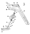
- a cross-stiffening tubular structure 17 which consist of two laterally outer upright reinforcement tubes 18 and one tubular stiffening element 19 extending across the width of the body composed.
- each upright reinforcement tube 18 is relative to an adjacent one large-area gusset 20 connected, with this gusset 20 a Large-scale force transmission is guaranteed in the event of a side impact load.
- each gusset plate 20 surrounds the sections Outside of the longitudinal sill 10 and is attached to it (for example by Welding). Thus, the lower end region 21 of each gusset plate 20 is supported Longitudinal sill 10. Immediately above the elevation of the Longitudinal sill 10 is an inwardly projecting reinforcing tube 18 Support tube 22 led away, in the area of the passenger compartment 8 with the outer End 23 of the transverse tubular stiffening element 19 rigid connected is.
- the gusset plate 20 with the upright attached Reinforcement beam 18 and the transverse support tube 22 form one Pre-assembly.
- the gusset plate 20 has above the Longitudinal sill 10 an upright, open to the outside groove 24 in which the upright reinforcement tube 18 is inserted.
- the reinforcement tube 18 is in the embodiment by a hollow square tube formed, which is partially welded to the gusset plate 20.
- the Square tube is chamfered at the top and bottom. The outside of the Square tube is approximately aligned with the adjacent wall sections of the Gusset plate 20.
- the outer end of the support tube 22 is with the reinforcement tube 18 welded.
- the node element 20 is the wider one internally arranged B-pillar 9 and runs at a short distance to the outer side part 6. Furthermore, the node element 20 - extends Seen height direction - not up to the belt line 2, but ends below approximately at the top of a barrier.
- the support tubes 22 are formed according to FIG. 2 by two short straight tubes are aligned approximately horizontally and extend in the transverse direction of the vehicle. Both Support tubes 22 are partially in through the inner B-pillar 9 in passed horizontally and protrude beyond the respective B-pillar 9 inside.
- the transverse tubular stiffening element 19 is on both of them outer ends either directly or via patches, not shown Connecting tabs with the overlapping support tube 22 by welding connected.
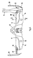
- the stiffening element 19 extends over a substantial part of it Transverse extent sunk in a transverse cavity 25 of the Rear seat system 11 or the center tunnel 12.
- the stiffening element 19 is composed of a middle one raised section 26 and two transverse, approximately horizontal Sections 27 together. Only in the two outer connection areas 28 the stiffening element 19 is freely accessible.
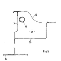
- the transverse cavity 25 is in the area of the rear seat system 11 by the front upright heel plate 14, the upper seat recess 16 and a lower one Strike plate 29 formed on the heel plate 14 and the underside of the seat recess 16 is connected (Fig. 5).
- Both sides of the raised section 26 are on the underside of the transverse horizontal sections 27 of the stiffening element 19 holder 30 welded with one or more downstanding stud bolts 31, whereby the stiffening element 19 on the seat recess 16 of the rear seat system 11 is screwable.
- This also runs in the area of the central tunnel 12 Stiffening element 19 sunk in a cavity that passes through the central tunnel 12 and an attached section of the seat recess 16 is formed.
- a transverse gear bridge 32 For further stiffening of the passenger cell 8 is below the center tunnel 12 a transverse gear bridge 32 a further bent tubular element 33 integrated, through which the central tunnel 12 is additionally stiffened.
- the pipe element 33 is firmly connected to the upper edge of the gear bridge 32.
- the Gear bridge 32 is separated and removed from the stiffening element 19 on the structure attached.
- the support tube 22 lies above the stiffening element 19 and both components 19, 22 are aligned when viewed in plan view. Both components 19, 22 could, however, also run at the same height and one behind the other be arranged.
- the support tube 22 and the stiffening element 19 overlap sections. The connection of the support tube 22 to the stiffening element 19 takes place at Compensation of tolerances only in the vehicle, specifically within the passenger compartment 8.
- Above the Belt line 2 ' runs an upright hollow beam construction, the upper edge of which upper roof frame is connected.
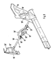
- the transverse stiffening tube construction 17 'at the Coupe version is in the area of the transverse stiffening element 19 ' identically designed as in the convertible version.
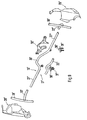
- the reinforcing tube 18' with the gusset plate 20 ' is welded.
- the gusset plate 20 ' surrounds in sections the outside of the longitudinal sill 10 'and is firmly connected to this.
- the Gusset plate 20 ' is above the longitudinal sill 10' by means of flanges on the edge the outer contour of the standing web plate 34 brought up and is with this welded.
- the gusset plate 20 ' extends only in a lower part of the Height of the B-pillar 9 '.
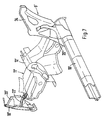
- the support tube 22 ' From the inner reinforcement tube 18 'is a bow-shaped support tube 22 'guided inwards above the longitudinal sill 10', the support tube 22 ' and the stiffening element 19 'are connected to one another in exactly the same way as in the case of initially described tube construction 17.
- the support tube 22 ' is in this Execution bent forward because the upright reinforcement tube 18 '- in Seen in the longitudinal direction - an offset to the transverse stiffening element 19 ' having.
Landscapes
- Engineering & Computer Science (AREA)
- Chemical & Material Sciences (AREA)
- Combustion & Propulsion (AREA)
- Transportation (AREA)
- Mechanical Engineering (AREA)
- Body Structure For Vehicles (AREA)
Description
- Fig. 1
- eine Teilseitenansicht auf ein durch ein Cabriolet gebildetes Kraftfahrzeug,
- Fig. 2
- eine perspektivische Teilansicht von schräg vorne auf einen Längsschweller, eine aufrechte B-Säule und einen Teilbereich der Hintersitzanlage der Fahrgastzelle sowie eine erste Ausführungsform einer erfindungsgemäßen Rohrkonstruktion,
- Fig. 3
- eine perspektivische Teilansicht auf die Bauteile der ersten Ausführungsform der Rohrkonstruktion sowie auf einen Längsschweller und die angrenzende Säule,
- Fig. 4
- eine Ansicht von vorne auf die Rohrkonstruktion und den angrenzenden Aufbau,
- Fig. 5
- einen Schnitt nach der Linie V-V der Fig. 4 in größerer Darstellung,
- Fig. 6
- eine Teilseitenansicht auf ein durch ein Coupe gebildetes Kraftfahrzeug,
- Fig. 7
- eine perspektivische Teilansicht auf eine zweite Ausführungsform einer querversteifenden Rohrkonstruktion und den angrenzenden Aufbau,
- Fig. 8
- eine perspektivische Teilansicht auf die zweite Ausführungsform der Rohrkonstruktion und
- Fig. 9
- eine Explosionsdarstellung der Bauteile der zweiten Ausführungsform der Rohrkonstruktion.
Claims (12)
- Fahrgastzelle für einen Personenkraftwagen mit jeweils einer B-Säule (9) auf jeder Karosserieseite, die in einen untenliegenden Längsschwelle (10, 10') mündet, wobei zur Erhöhung der Quersteifigkeit der Fahrgastzelle bei Seitenaufprallbelastungen eine querversteifende Rohrkonstruktion vorgesehen ist, die sich aus zwei seitlich außenliegenden, aufrechten Verstärkungsrohren (18, 18') und einem sich über die Karosseriebreite erstreckenden, rohrförmigen Versteifungselement (19, 19') zusammensetzt, dadurch gekennzeichnet, daß jedes aufrechte Verstärkungsrohr (18, 18') an ein angrenzendes Knotenblech (20, 20') angebunden ist, dessen unterer Randbereich sich an der Außenseite des Längsschwellers (10, 10') abstützt und daß von jedem Verstärkungsrohr (18, 18') oberhalb der Höhenerstreckung des Längsschwellers (10, 10') ein nach innen ragendes Stützrohr (22, 22') weggeführt ist, das im Bereich der Fahrgastzelle (8, 8') jeweils mit dem äußeren Ende des querverlaufenden rohrförmigen Versteifungselementes (19, 19') starr verbunden ist.
- Fahrgastzelle nach Anspruch 1, dadurch gekennzeichnet, daß das querverlaufende rohrförmige Versteifungselement (19, 19') an seinen beiden äußeren Enden (23, 23') entweder direkt oder mittels Verbindungslaschen mit dem überlappenden Stützrohr (22, 22') fest verbunden ist.
- Fahrgastzelle nach Anspruch 1, dadurch gekennzeichnet, daß das Versteifungselement (19, 19') über einen wesentlichen Teil seiner Quererstreckung versenkt in einem querverlaufenden Hohlraum (25, 25') der Hintersitzanlage (11) bzw. des Mitteltunnels (12) verläuft.
- Fahrgastzelle nach den Ansprüchen 1 und 3, dadurch gekennzeichnet, daß das Versteifungselement (19, 19') im Bereich des Mitteltunnels (12) einen hochgezogenen Abschnitt (26) aufweist.
- Fahrgastzelle nach Anspruch 4, dadurch gekennzeichnet, daß beiderseits des hochgezogenen Abschnitts ((26) des Versteifungselements (19, 19') an dessen Unterseite angeschweißte Halter ((30) mit aufrechten, nach unten ragenden Stehbolzen ((31) vorgesehen sind, wobei das Versteifungselement (19, 19') an der Hintersitzanlage (11) festlegbar ist.
- Fahrgastzelle nach einem oder mehreren der vorangegangenen Ansprüche, dadurch gekennzeichnet, daß unterhalb des hochgezogenen Abschnitts (26) des Versteifungselementes (19, 19') an einer querverlaufenden Getriebebrücke (32) ein integriertes Rohrelement (33) vorgesehen ist.
- Fahrgastzelle nach Anspruch 1, dadurch gekennzeichnet, daß das aufrechte Verstärkungsrohr (18, 18'), das Knotenblech (20, 20') und das nach innenragende Stützrohr (22, 22') eine Vormontageeinheit bilden, die zumindest mit dem Längsschweller (10, 10') und dem querverlaufenden Versteifungselement (19, 19') verbindbar ist.
- Fahrgastzelle nach Anspruch 1, dadurch gekennzeichnet, daß das aufrechte Verstärkungsrohr (18') an der Innenseite des Knotenblechs (20') angeschweißt ist und daß vom Verstärkungsrohr (18') ein etwa horizontal verlaufendes gebogenes Stützrohr (22') zum in Fahrtrichtung weiter hintenliegenden querverlaufenden Versteifungselement (19') weggeführt ist.
- Fahrgastzelle nach Anspruch 8, dadurch gekennzeichnet, daß das Knotenblech (20') örtlich an ein aufrechtes Stegblech (34) der B-Säule (9') herangeführt und mit diesem örtlich verbunden ist.
- Fahrgastzelle nach Anspruch 1, dadurch gekennzeichnet, daß am Knotenblech (20) eine aufrechte, etwa U-förmig profilierte, nach außen hin offene Rinne (24) ausgebildet ist, in die das aufrechte Verstärkungsrohr (18) eingesetzt und fest mit dem Knotenblech (20) verbunden ist.
- Fahrgastzelle nach Anspruch 10, dadurch gekennzeichnet, daß das aufrechte Verstärkungsrohr (18) einen rechteckförmigen oder quadratischen Querschnitt aufweist.
- Fahrgastzelle nach einem oder mehreren der vorangegangenen Ansprüche, dadurch gekennzeichnet, daß das Knotenblech (20) außerhalb der B-Säule (9) und zwar benachbart eines Seitenteiles (6) des Aufbaus verläuft und daß das querverlaufende horizontale Stützrohr (22) durch die weiter innenliegende B-Säule (9) hindurchgeführt ist.
Applications Claiming Priority (2)
| Application Number | Priority Date | Filing Date | Title |
|---|---|---|---|
| DE19811215A DE19811215B4 (de) | 1998-03-14 | 1998-03-14 | Fahrgastzelle für einen Personenkraftwagen |
| DE19811215 | 1998-03-14 |
Publications (3)
| Publication Number | Publication Date |
|---|---|
| EP0943530A2 EP0943530A2 (de) | 1999-09-22 |
| EP0943530A3 EP0943530A3 (de) | 2002-12-11 |
| EP0943530B1 true EP0943530B1 (de) | 2004-08-18 |
Family
ID=7860976
Family Applications (1)
| Application Number | Title | Priority Date | Filing Date |
|---|---|---|---|
| EP99100932A Expired - Lifetime EP0943530B1 (de) | 1998-03-14 | 1999-01-20 | Fahrgastzelle für einen Personenkraftwagen |
Country Status (5)
| Country | Link |
|---|---|
| US (1) | US6168228B1 (de) |
| EP (1) | EP0943530B1 (de) |
| JP (1) | JP4102508B2 (de) |
| DE (2) | DE19811215B4 (de) |
| ES (1) | ES2222624T3 (de) |
Cited By (3)
| Publication number | Priority date | Publication date | Assignee | Title |
|---|---|---|---|---|
| EP1780103A1 (de) * | 2005-10-29 | 2007-05-02 | Dr.Ing. h.c.F. Porsche Aktiengesellschaft | Vorrichtung zur Aufnahme von Seitenkräften bei einem Seitenaufprall eines Kraftfahrzeugs |
| DE102005051947B4 (de) * | 2005-10-29 | 2007-09-27 | Dr.Ing.H.C. F. Porsche Ag | Vorrichtung zur Aufnahme von Seitenkräften bei einem Seitenaufprall eines Kraftfahrzeugs |
| DE102006024814B4 (de) * | 2006-05-27 | 2015-07-16 | Dr. Ing. H.C. F. Porsche Aktiengesellschaft | Fahrgastzelle für ein Kraftfahrzeug |
Families Citing this family (31)
| Publication number | Priority date | Publication date | Assignee | Title |
|---|---|---|---|---|
| DE29714656U1 (de) * | 1997-08-16 | 1998-12-17 | Wilhelm Karmann GmbH, 49084 Osnabrück | Kraftfahrzeug |
| DE10007421A1 (de) * | 2000-02-18 | 2001-08-23 | Volkswagen Ag | Verstärkungsstrebe für ein Kfz im Seitenbereich |
| DE10117010A1 (de) * | 2001-04-05 | 2002-10-10 | Daimler Chrysler Ag | Karosserierahmen eines Kraftfahrzeuges |
| US6679546B2 (en) * | 2001-06-12 | 2004-01-20 | Mazda Motor Corporation | Front body structure of vehicle |
| FR2829457B1 (fr) * | 2001-09-13 | 2004-12-03 | Peugeot Citroen Automobiles Sa | Chassis de vehicule automobile |
| US6655729B2 (en) * | 2001-09-13 | 2003-12-02 | Intier Automotive Inc. | Bridge assembly |
| DE10209188B4 (de) * | 2002-03-04 | 2004-07-22 | Daimlerchrysler Ag | Tragstruktur einer selbsttragenden Kraftfahrzeugkarosserie |
| US7246845B2 (en) * | 2003-09-03 | 2007-07-24 | Asc Incorporated | Structural seat system for an automotive vehicle |
| US7481486B2 (en) * | 2003-09-03 | 2009-01-27 | Specialty Vehicle Acquisition Corp. | Structural seat system for an automotive vehicle |
| US7413240B2 (en) * | 2003-09-03 | 2008-08-19 | Specialty Vehicle Acquisition Corp. | Structural system for a convertible automotive vehicle |
| US7413242B2 (en) * | 2003-09-03 | 2008-08-19 | Specialty Vehicle Acquisition Corp. | Structural seat system for an automotive vehicle |
| US20050046235A1 (en) | 2003-09-03 | 2005-03-03 | Robertson James E. | Structural reinforcement system for an automotive vehicle |
| DE102004014796A1 (de) * | 2004-03-24 | 2005-10-20 | Karmann Gmbh W | Kraftfahrzeug mit Seitenaufprallverstärkung |
| JP4754814B2 (ja) * | 2004-12-14 | 2011-08-24 | ヤマハ発動機株式会社 | 車両の車体用補強装置 |
| JP4380565B2 (ja) * | 2005-03-10 | 2009-12-09 | トヨタ自動車株式会社 | 側突荷重伝達構造 |
| DE102005015439A1 (de) * | 2005-04-05 | 2006-10-12 | Wilhelm Karmann Gmbh | Verstärkungsrahmen für eine Fahrzeugstruktur sowie eine Fahrzeugstruktur mit einem solchen Verstärkungsrahmen |
| US7422271B2 (en) | 2005-06-01 | 2008-09-09 | Dr. Ing. H.C.F. Porsche Aktiengesellschaft | Passenger cell for a passenger vehicle |
| USD543135S1 (en) | 2005-08-12 | 2007-05-22 | Asc Incorporated | Automotive vehicle and/or toy replica thereof |
| CN100434327C (zh) * | 2005-11-24 | 2008-11-19 | 叶子青 | 乘用车侧面碰撞抗侧体变形装置及带有该装置的乘用车 |
| ATE432864T1 (de) * | 2006-01-05 | 2009-06-15 | Ford Global Tech Llc | Verbindungsanordnung für stosskraft |
| US7237833B1 (en) * | 2006-03-07 | 2007-07-03 | Nissan Technical Center North America, Inc. | Vehicle body structure |
| DE102006014981A1 (de) * | 2006-03-31 | 2007-10-04 | Dr.Ing.H.C. F. Porsche Ag | Querträgerstruktur für einen Sitzbereich eines Fahrzeugs |
| DE102006055721A1 (de) * | 2006-11-25 | 2008-05-29 | Dr.Ing.H.C. F. Porsche Ag | Kraftfahrzeug mit Stirnwandquerträger |
| JP5248852B2 (ja) * | 2007-12-27 | 2013-07-31 | ヤマハ発動機株式会社 | 車体用振動減衰装置 |
| DE102008039404A1 (de) | 2008-08-22 | 2010-02-25 | Wilhelm Karmann Gmbh | Vorrichtung zur Querversteifung eines Fahrzeuges, insbesondere eines Cabriolets |
| DE102008049986A1 (de) | 2008-10-01 | 2010-04-08 | Dr.Ing.H.C.F.Porsche Aktiengesellschaft | Kraftfahrzeug mit einer Fondseitenscheibe |
| DE102009005759B4 (de) * | 2009-01-23 | 2015-10-15 | Daimler Ag | Tunnelstrebe für eine Karosserie eines Personenkraftwagens sowie Karosserie eines Personenkraftwagens |
| DE102009012057B4 (de) * | 2009-03-06 | 2023-08-03 | Dr. Ing. H.C. F. Porsche Aktiengesellschaft | Vorrichtung zum Aufnehmen von Seitenkräften und Kraftfahrzeug mit einer derartigen Vorrichtung |
| DE102013004306A1 (de) * | 2013-03-13 | 2014-09-18 | Daimler Ag | Querträger für den Bodenbereich einer Kraftfahrzeug-Rohbaustruktur, Verfahren zur Herstellung eines Querträgers und Kraftfahrzeug-Robaustruktur |
| US10351176B2 (en) * | 2017-03-22 | 2019-07-16 | Honda Motor Co., Ltd. | Vehicle body structure for absorbing side impacts |
| US10377218B1 (en) | 2018-06-07 | 2019-08-13 | Ford Global Technologies, Llc | Reinforced heel kick assembly and heel kick reinforcement method |
Family Cites Families (8)
| Publication number | Priority date | Publication date | Assignee | Title |
|---|---|---|---|---|
| GB189622366A (en) | 1896-10-09 | 1897-08-28 | Frederick Parker | Improvements in Road Vehicles Propelled by Horses or Motors. |
| FR2500399A1 (fr) * | 1981-02-20 | 1982-08-27 | Citroen Sa | Carrosserie ou caisse de securite pour vehicules automobiles |
| US4529243A (en) * | 1983-04-29 | 1985-07-16 | Asc Incorporated | Vehicle with a convertible top |
| US4660345A (en) * | 1984-10-10 | 1987-04-28 | Mr. Gasket Company | Vehicle space frame, castings therefor and method for remote construction |
| AT400325B (de) * | 1993-09-07 | 1995-12-27 | Steyr Daimler Puch Ag | Kraftfahrzeugkörper |
| DE19603098C2 (de) * | 1996-01-29 | 1998-03-19 | Daimler Benz Ag | Fahrgastzelle für einen Personenkraftwagen |
| JPH10218038A (ja) * | 1997-02-06 | 1998-08-18 | Shigeru Ito | 車のボデイ用補強バー装置 |
| DE29714656U1 (de) * | 1997-08-16 | 1998-12-17 | Wilhelm Karmann GmbH, 49084 Osnabrück | Kraftfahrzeug |
-
1998
- 1998-03-14 DE DE19811215A patent/DE19811215B4/de not_active Expired - Fee Related
-
1999
- 1999-01-20 EP EP99100932A patent/EP0943530B1/de not_active Expired - Lifetime
- 1999-01-20 DE DE59910233T patent/DE59910233D1/de not_active Expired - Lifetime
- 1999-01-20 ES ES99100932T patent/ES2222624T3/es not_active Expired - Lifetime
- 1999-03-15 US US09/267,701 patent/US6168228B1/en not_active Expired - Lifetime
- 1999-03-15 JP JP06853799A patent/JP4102508B2/ja not_active Expired - Fee Related
Cited By (7)
| Publication number | Priority date | Publication date | Assignee | Title |
|---|---|---|---|---|
| EP1780103A1 (de) * | 2005-10-29 | 2007-05-02 | Dr.Ing. h.c.F. Porsche Aktiengesellschaft | Vorrichtung zur Aufnahme von Seitenkräften bei einem Seitenaufprall eines Kraftfahrzeugs |
| DE102005051948A1 (de) * | 2005-10-29 | 2007-05-03 | Dr.Ing.H.C. F. Porsche Ag | Vorrichtung zur Aufnahme von Seitenkräften bei einem Seitenaufprall eines Kraftfahrzeugs |
| DE102005051947B4 (de) * | 2005-10-29 | 2007-09-27 | Dr.Ing.H.C. F. Porsche Ag | Vorrichtung zur Aufnahme von Seitenkräften bei einem Seitenaufprall eines Kraftfahrzeugs |
| DE102005051948B4 (de) * | 2005-10-29 | 2007-12-06 | Dr.Ing.H.C. F. Porsche Ag | Vorrichtung zur Aufnahme von Seitenkräften bei einem Seitenaufprall eines Kraftfahrzeugs |
| US7448674B2 (en) | 2005-10-29 | 2008-11-11 | Dr. Ing. H.C. F. Porsche Aktiengesellschaft | Device for absorbing lateral forces in a side impact in a motor vehicle |
| US7581781B2 (en) | 2005-10-29 | 2009-09-01 | Dr. Ing. H.C.F. Porsche Aktiengesellschaft | Device for absorbing lateral forces during a side impact of a motor vehicle |
| DE102006024814B4 (de) * | 2006-05-27 | 2015-07-16 | Dr. Ing. H.C. F. Porsche Aktiengesellschaft | Fahrgastzelle für ein Kraftfahrzeug |
Also Published As
| Publication number | Publication date |
|---|---|
| DE19811215A1 (de) | 1999-09-16 |
| JPH11314576A (ja) | 1999-11-16 |
| EP0943530A3 (de) | 2002-12-11 |
| US6168228B1 (en) | 2001-01-02 |
| JP4102508B2 (ja) | 2008-06-18 |
| EP0943530A2 (de) | 1999-09-22 |
| DE59910233D1 (de) | 2004-09-23 |
| ES2222624T3 (es) | 2005-02-01 |
| DE19811215B4 (de) | 2007-06-21 |
Similar Documents
| Publication | Publication Date | Title |
|---|---|---|
| DE19811215B4 (de) | Fahrgastzelle für einen Personenkraftwagen | |
| DE4013784C2 (de) | Wagenkasten, insbesondere für Personenkraftwagen | |
| DE60018628T2 (de) | Karosserieaufbau für Kraftfahrzeug | |
| EP1490256B1 (de) | Kraftfahrzeug | |
| EP1273502B1 (de) | Kraftfahrzeugkarosserie | |
| DE102008056507B4 (de) | Fahrzeugaufbau für ein Kraftfahrzeug | |
| DE19948363A1 (de) | Mittelsäulenstruktur | |
| DE19634601A1 (de) | Fahrzeugkarosseriestruktur | |
| EP1268261A2 (de) | Fahrzeugkarosserieboden und plattformsystem | |
| EP0897853A2 (de) | Kraftfahrzeug mit Verstärkungen im Bereich der B-Säule | |
| DE102005051948A1 (de) | Vorrichtung zur Aufnahme von Seitenkräften bei einem Seitenaufprall eines Kraftfahrzeugs | |
| EP1730015B1 (de) | Kraftfahrzeug mit seitenaufprallverstärkung | |
| DE19841331C2 (de) | Karosseriebodenstruktur für ein Kraftfahrzeug | |
| EP1702833B1 (de) | Aufbaustruktur für einen mit einem Fliessheck versehenen Personenkraftwagen | |
| EP1728707B1 (de) | Fahrgastzelle für einen Personenkraftwagen | |
| DE19943296C2 (de) | Fahrgastzelle für einen Personenkraftwagen | |
| DE19633908B4 (de) | Bodengruppe für ein Fahrzeug | |
| DE19821107C2 (de) | Rohbaukarosserie für einen Personenkraftwagen | |
| DE4205891C2 (de) | Bodengruppe für Kraftfahrzeuge | |
| DE10302756B4 (de) | Tragstruktur für eine Kraftwagenkarosserie | |
| DE10014367A1 (de) | Aufbaustruktur für ein Kraftfahrzeug | |
| DE102005051440B4 (de) | Seitenwandbaugruppe für eine Kraftfahrzeugkarosserie eines insbesondere Personenkraftfahrzeuges | |
| DE102006012628A1 (de) | Karosseriestruktur für ein Kraftfahrzeug | |
| EP0952022B1 (de) | Klappverdeck für Cabriofahrzeuge | |
| DE102014005078B4 (de) | Fersenblechstruktur für eine Fahrzeugkarosserie und Karosserie für ein Fahrzeug |
Legal Events
| Date | Code | Title | Description |
|---|---|---|---|
| PUAI | Public reference made under article 153(3) epc to a published international application that has entered the european phase |
Free format text: ORIGINAL CODE: 0009012 |
|
| AK | Designated contracting states |
Kind code of ref document: A2 Designated state(s): AT BE CH CY DE DK ES FI FR GB GR IE IT LI LU MC NL PT SE |
|
| AX | Request for extension of the european patent |
Free format text: AL;LT;LV;MK;RO;SI |
|
| PUAL | Search report despatched |
Free format text: ORIGINAL CODE: 0009013 |
|
| AK | Designated contracting states |
Kind code of ref document: A3 Designated state(s): AT BE CH CY DE DK ES FI FR GB GR IE IT LI LU MC NL PT SE |
|
| AX | Request for extension of the european patent |
Free format text: AL;LT;LV;MK;RO;SI |
|
| RIC1 | Information provided on ipc code assigned before grant |
Free format text: 7B 62D 25/20 A, 7B 62D 21/10 B, 7B 62D 27/04 B |
|
| 17P | Request for examination filed |
Effective date: 20030611 |
|
| AKX | Designation fees paid |
Designated state(s): DE ES FR GB IT |
|
| GRAP | Despatch of communication of intention to grant a patent |
Free format text: ORIGINAL CODE: EPIDOSNIGR1 |
|
| GRAS | Grant fee paid |
Free format text: ORIGINAL CODE: EPIDOSNIGR3 |
|
| GRAA | (expected) grant |
Free format text: ORIGINAL CODE: 0009210 |
|
| AK | Designated contracting states |
Kind code of ref document: B1 Designated state(s): DE ES FR GB IT |
|
| REG | Reference to a national code |
Ref country code: GB Ref legal event code: FG4D Free format text: NOT ENGLISH |
|
| REG | Reference to a national code |
Ref country code: IE Ref legal event code: FG4D Free format text: GERMAN |
|
| REF | Corresponds to: |
Ref document number: 59910233 Country of ref document: DE Date of ref document: 20040923 Kind code of ref document: P |
|
| GBT | Gb: translation of ep patent filed (gb section 77(6)(a)/1977) |
Effective date: 20040914 |
|
| REG | Reference to a national code |
Ref country code: ES Ref legal event code: FG2A Ref document number: 2222624 Country of ref document: ES Kind code of ref document: T3 |
|
| REG | Reference to a national code |
Ref country code: IE Ref legal event code: FD4D |
|
| ET | Fr: translation filed | ||
| PLBE | No opposition filed within time limit |
Free format text: ORIGINAL CODE: 0009261 |
|
| STAA | Information on the status of an ep patent application or granted ep patent |
Free format text: STATUS: NO OPPOSITION FILED WITHIN TIME LIMIT |
|
| 26N | No opposition filed |
Effective date: 20050519 |
|
| PGFP | Annual fee paid to national office [announced via postgrant information from national office to epo] |
Ref country code: ES Payment date: 20090219 Year of fee payment: 11 |
|
| REG | Reference to a national code |
Ref country code: FR Ref legal event code: TP |
|
| REG | Reference to a national code |
Ref country code: FR Ref legal event code: CD |
|
| REG | Reference to a national code |
Ref country code: FR Ref legal event code: TP |
|
| REG | Reference to a national code |
Ref country code: ES Ref legal event code: FD2A Effective date: 20110404 |
|
| REG | Reference to a national code |
Ref country code: GB Ref legal event code: 732E Free format text: REGISTERED BETWEEN 20110310 AND 20110316 |
|
| REG | Reference to a national code |
Ref country code: GB Ref legal event code: 732E Free format text: REGISTERED BETWEEN 20110331 AND 20110406 |
|
| PG25 | Lapsed in a contracting state [announced via postgrant information from national office to epo] |
Ref country code: ES Free format text: LAPSE BECAUSE OF NON-PAYMENT OF DUE FEES Effective date: 20110322 |
|
| PG25 | Lapsed in a contracting state [announced via postgrant information from national office to epo] |
Ref country code: ES Free format text: LAPSE BECAUSE OF NON-PAYMENT OF DUE FEES Effective date: 20100121 |
|
| REG | Reference to a national code |
Ref country code: FR Ref legal event code: PLFP Year of fee payment: 17 |
|
| PGFP | Annual fee paid to national office [announced via postgrant information from national office to epo] |
Ref country code: DE Payment date: 20141223 Year of fee payment: 17 Ref country code: IT Payment date: 20150127 Year of fee payment: 17 |
|
| PGFP | Annual fee paid to national office [announced via postgrant information from national office to epo] |
Ref country code: GB Payment date: 20150121 Year of fee payment: 17 Ref country code: FR Payment date: 20150122 Year of fee payment: 17 |
|
| REG | Reference to a national code |
Ref country code: DE Ref legal event code: R119 Ref document number: 59910233 Country of ref document: DE |
|
| GBPC | Gb: european patent ceased through non-payment of renewal fee |
Effective date: 20160120 |
|
| REG | Reference to a national code |
Ref country code: FR Ref legal event code: ST Effective date: 20160930 |
|
| PG25 | Lapsed in a contracting state [announced via postgrant information from national office to epo] |
Ref country code: GB Free format text: LAPSE BECAUSE OF NON-PAYMENT OF DUE FEES Effective date: 20160120 Ref country code: DE Free format text: LAPSE BECAUSE OF NON-PAYMENT OF DUE FEES Effective date: 20160802 |
|
| PG25 | Lapsed in a contracting state [announced via postgrant information from national office to epo] |
Ref country code: FR Free format text: LAPSE BECAUSE OF NON-PAYMENT OF DUE FEES Effective date: 20160201 |
|
| PG25 | Lapsed in a contracting state [announced via postgrant information from national office to epo] |
Ref country code: IT Free format text: LAPSE BECAUSE OF NON-PAYMENT OF DUE FEES Effective date: 20160120 |