EP0942209B1 - Cartouche d'étanchéité munie d'un dispositif de retenue - Google Patents
Cartouche d'étanchéité munie d'un dispositif de retenue Download PDFInfo
- Publication number
- EP0942209B1 EP0942209B1 EP99103496A EP99103496A EP0942209B1 EP 0942209 B1 EP0942209 B1 EP 0942209B1 EP 99103496 A EP99103496 A EP 99103496A EP 99103496 A EP99103496 A EP 99103496A EP 0942209 B1 EP0942209 B1 EP 0942209B1
- Authority
- EP
- European Patent Office
- Prior art keywords
- ring
- plastic ring
- plastic
- metal retainer
- groove
- Prior art date
- Legal status (The legal status is an assumption and is not a legal conclusion. Google has not performed a legal analysis and makes no representation as to the accuracy of the status listed.)
- Expired - Lifetime
Links
Images

Classifications
-
- F—MECHANICAL ENGINEERING; LIGHTING; HEATING; WEAPONS; BLASTING
- F16—ENGINEERING ELEMENTS AND UNITS; GENERAL MEASURES FOR PRODUCING AND MAINTAINING EFFECTIVE FUNCTIONING OF MACHINES OR INSTALLATIONS; THERMAL INSULATION IN GENERAL
- F16J—PISTONS; CYLINDERS; SEALINGS
- F16J15/00—Sealings
- F16J15/16—Sealings between relatively-moving surfaces
- F16J15/32—Sealings between relatively-moving surfaces with elastic sealings, e.g. O-rings
- F16J15/3204—Sealings between relatively-moving surfaces with elastic sealings, e.g. O-rings with at least one lip
- F16J15/3216—Sealings between relatively-moving surfaces with elastic sealings, e.g. O-rings with at least one lip supported in a direction parallel to the surfaces
-
- F—MECHANICAL ENGINEERING; LIGHTING; HEATING; WEAPONS; BLASTING
- F16—ENGINEERING ELEMENTS AND UNITS; GENERAL MEASURES FOR PRODUCING AND MAINTAINING EFFECTIVE FUNCTIONING OF MACHINES OR INSTALLATIONS; THERMAL INSULATION IN GENERAL
- F16J—PISTONS; CYLINDERS; SEALINGS
- F16J15/00—Sealings
- F16J15/16—Sealings between relatively-moving surfaces
- F16J15/32—Sealings between relatively-moving surfaces with elastic sealings, e.g. O-rings
- F16J15/3204—Sealings between relatively-moving surfaces with elastic sealings, e.g. O-rings with at least one lip
- F16J15/3208—Sealings between relatively-moving surfaces with elastic sealings, e.g. O-rings with at least one lip provided with tension elements, e.g. elastic rings
- F16J15/3212—Sealings between relatively-moving surfaces with elastic sealings, e.g. O-rings with at least one lip provided with tension elements, e.g. elastic rings with metal springs
-
- F—MECHANICAL ENGINEERING; LIGHTING; HEATING; WEAPONS; BLASTING
- F16—ENGINEERING ELEMENTS AND UNITS; GENERAL MEASURES FOR PRODUCING AND MAINTAINING EFFECTIVE FUNCTIONING OF MACHINES OR INSTALLATIONS; THERMAL INSULATION IN GENERAL
- F16J—PISTONS; CYLINDERS; SEALINGS
- F16J15/00—Sealings
- F16J15/16—Sealings between relatively-moving surfaces
- F16J15/32—Sealings between relatively-moving surfaces with elastic sealings, e.g. O-rings
- F16J15/3204—Sealings between relatively-moving surfaces with elastic sealings, e.g. O-rings with at least one lip
- F16J15/3232—Sealings between relatively-moving surfaces with elastic sealings, e.g. O-rings with at least one lip having two or more lips
- F16J15/3236—Sealings between relatively-moving surfaces with elastic sealings, e.g. O-rings with at least one lip having two or more lips with at least one lip for each surface, e.g. U-cup packings
-
- F—MECHANICAL ENGINEERING; LIGHTING; HEATING; WEAPONS; BLASTING
- F16—ENGINEERING ELEMENTS AND UNITS; GENERAL MEASURES FOR PRODUCING AND MAINTAINING EFFECTIVE FUNCTIONING OF MACHINES OR INSTALLATIONS; THERMAL INSULATION IN GENERAL
- F16J—PISTONS; CYLINDERS; SEALINGS
- F16J15/00—Sealings
- F16J15/16—Sealings between relatively-moving surfaces
- F16J15/32—Sealings between relatively-moving surfaces with elastic sealings, e.g. O-rings
- F16J15/3268—Mounting of sealing rings
Definitions
- the present invention generally relates to cartridge rotary seals that are pressed into a housing and provide a seal around a shaft at relatively low pressures under various fluid environments. More particularly, the present invention is directed to cartridge seal utilizing a separate metal retaining ring which provides axial and radial stress within a plastic sealing ring.
- Cartridge rotary seals have been used for many years in a variety of applications for the sealing of various types of fluids and gases. Generally these seals have employed various elastomers which are encased in metal. Typical materials utilized include various plastics and fluor polymers, for example, polytetrafluoroethylene, PTFE, because they exhibit relatively low friction, are chemically inert, and can withstand a variety of temperatures, thus enabling their use under conditions with no lubrication.
- PTFE polytetrafluoroethylene
- Such prior art cartridge seals utilize the elastomer in a bonded relationship with a circular metallic ring which often is U-shaped. The metallic portion of the seal is pressed into a housing while the elastomeric seal bears around the shaft.
- the plastic when plastics are utilized, such as fluoropolymers, the plastic is bonded to the metallic ring and the entire assembly is pressed into the housing with a degree of interference between the OD of the seal and the housing to permit retention of the seal assembly into the housing at the same time provides static sealing against the housing. Dynamic sealing between the seal and the shaft is provided by the elastomer contact therewith.
- the present invention provides for a rotary cartridge seal including a separate plastic ring and retainer which are uniquely locked together in order to provide a residual force therebetween in order to maintain the components together within specific temperature parameters.
- a rotary cartridge seal in accordance with the present invention generally includes a cold flowable plastic ring having a body for sealably engaging a housing bore and a lip for sealably engaging a shaft rotating within the housing bore.
- the usable plastic material must be cold flowable, such as, for example, polytetrafluoroethylene, PTFE.
- PTFE polytetrafluoroethylene
- a separable metal retainer provides means for fixing the plastic ring within the housing bore and around the shaft.
- the separable metal retainer includes a surface of revolution with a rear portion having a diameter suitable for press fitting into the housing bore and a front portion of lesser diameter ending in a ring.
- plastic rings in accordance with the present invention, have a relatively thick rear portion which enables a radial stress to be maintained therein. This stress is sufficient to maintain coupling between the plastic ring and the metal ring. When a plastic ring having a relatively thin rear portion is utilized, radial stress is maintained therein by specific configuration of the metal ring.
- the plastic ring internal groove has a diameter greater than the ring and the metal retainer front portion adjacent the ring has an outside diameter less than a contacted inside diameter of the plastic ring body adjacent the internal groove in order to maintain the radial stress in the plastic ring body.
- a width of the groove may be greater than a width of the metal ring but less than a width necessary to accept excess plastic forced by the radial stress due to cold flow into the groove means, thereby maintaining the axial stress in the plastic ring.
- Additional features may include head means, disposed at an end to the lip means, for engaging the shaft and a second groove may be provided adjacent the lip means in which a spring may be disposed for biasing the lip means against the shaft.
- the metal retainer may include a radially inward extending step for facilitating separation of the metal ring from the housing bore along with the plastic ring.
- the plastic ring may include flat portions on an outside surface, or circumference thereof, for restricting rotary motion of the plastic ring within the housing as the shaft is rotated.
- the internal groove may be generally rectangular with a rectangular or dovetail sidewall facing a rear side ring for enabling "cold flow" of plastic material thereinto.
- the metal retainer forward portion may include a thin cross section for providing a radial force on the plastic ring body means in order to cause radial stress therein.
- the plastic ring has a relatively thin body portion.
- the forward portion of the metal retainer include longitudinal grooves on the inside surface thereof for providing enhanced radial stress in the plastic ring body.
- a rotary cartridge seal 10 in accordance with the present invention which generally includes a cold flowable plastic ring 12 having a body 14 which provides means for sealably engaging a housing bore, formed in the housing 18, and a lip 20 which provides means for sealably engaging a shaft 26.
- the lip 20 is shown in dashed line 20A in a position before seal 10 is inserted between the housing 18 and shaft 26 and the dashed line 20b represents an effective range of sealing for the lip 20.
- the present invention utilizes a cold flowable plastic material, such as PTFE, PTFE compositions with various fillers or UHMW, to enable the flow of the material when properly stressed as in accordance with the present invention.
- a cold flowable plastic material such as PTFE, PTFE compositions with various fillers or UHMW
- the residual stress maintains the plastic ring in intimate contact with a separable metal retainer 30 in a manner which creates residual stress for maintaining the components together within specific temperature parameters.
- the separable metal retainer 30 includes a surface of revolution 34 having a rear portion 36 with a diameter suitable for press fitting into the housing bore 16 and a front portion 38 having a lesser diameter which ends in a ring 40.
- An internal grove 44 within the plastic ring body 14, as more clearly shown in Figure 2, has a radius r 1 greater than a ring radius r 2 , resulting in a clearance C 1 .
- Such clearance facilitates assembly of the metal part into the plastic groove.
- the metal ring front portion 38 adjacent the ring 40 has an outside radius less than a contacted inside radius of the plastic ring body 14 indicated as interference I 1 , in order to maintain the radial stress in the plastic ring body 14.
- a width of the groove 44 is greater than a width of the ring as indicated by the clearance C 2.
- Such clearance facilitates assembly of the two parts.
- This deformation force can be applied radially, axially or a combination of radial axial forces with the purpose of providing locking action between the plastic ring 12 and the metal retainer 30.
- seals in accordance with the present invention provide sealing throughout a greater temperature range.
- the metallic retainer 30 may be designed to add flexibility and increase the loading force as the temperature increases and the bearing stress of the PTFE decreases. In this manner a spring force provided by the metallic retainer 30 maintains an improved sealing ability of the cartridge seal 10 while maintaining contact between the seal OD and the housing 18.
- the groove 44 in the plastic ring body 14 and the ring 40 portion of the metal retainer 30 is assembled as a rotary cartridge seal 10 by forcing the metal retainer 30 into the plastic ring 12 which expands the plastic ring 12 radially and causes the plastic ring 12 to "snap" which creates a diametrical interference between the ID of the plastic ring 12 and the OD of the metal retainer 30 at an area A so that a residual circular stress remains.
- “snap” refers to the radial and/or axial expansion of the plastic which allows plastic to return to its normal position but creates a radial or axial residual stress around the expanded surfaces.
- the plastic ring 12 and the metal retainer 30 may be locked in place by either an axial locking action, a radial locking action or a combination of both. That is, there may be axial clearance at assembly, which may or may not be filled by the cold flowing of the material, as in C 2 , Figure 2, or radial clearance at assembly as in C 1 and such clearance may remain or may not remain after cold flow of the material. But in all cases, there will be some sort of residual induced stress, be axial, radial, or a combination of axial and radial.
- the plastic PTFE ring may have an outside radius of between about 19.000 mm and about 19.126 mm with a housing having a radius between about 19.063 mm and about 19.037 vacating a radial interference ranging between about 0.089 mm - 0.0035" to about 0.063 mm - 0.0024".
- the plastic ring groove may have a radius of r 1 between about 17.907 mm and about 17.882 mm with a metal ring groove diameter r 2 of between about 17.832 mm and about 17.356 mm having a radial clearance between about 0.000 mm to about 0.051 mm.
- the plastic ring groove radius r 5 may have a radius of between about 17.526 mm and about 17.500 mm with a metal ring radius r 4 of between about 17.597 mm and about 17.551 mm having a radial interference between about 0.092 mm to about 0.025 mm.
- the difference between the groove 44 width and ring 40 width may provide for clearance C 2 of between about 0.000 mm and about 0.051 mm.
- This configuration enables sealing between the housing 18 and the shaft 26 at temperatures between about -20°C. and about 100°C. at shaft rotational speeds of up to 5000 RPM, when using PTFE compositions, as for example, containing 20% carbon, 5% graphite, 78% PTFE.
- plastic ring 62 includes a second groove 64 adjacent a lip 66 is provided for receiving a spring 68 for biasing the lip 66 against the shaft 26.
- a metal retainer 70 which is similar in design to the retainer 30 but which includes an inwardly extending step 72 which provides means for facilitating separation of the metal retainer 70 from the housing bore 16 along with the plastic ring 62.
- FIG. 4 A further embodiment 78 of the present invention is shown in Figure 4 in which common character references refer to identical or substantially the same elements shown in Figure 1.
- a plastic ring 80 includes a lip portion 82 having a head 84 thereof which provides a means for contacting the shaft 26 over a greater area.
- yet another embodiment 90 in accordance with the present invention includes a plastic ring 92 and a metal retainer 94.
- the plastic ring 92 includes a relatively thin wall thickness t 1 , and accordingly no radial snapping action occurs due to the flexibility of the plastic ring 92 at that point.
- snapping action occurs axially as hereinabove described in accordance with the embodiments shown in Figures 1-4.
- the ID of the plastic ring 92 expands radially during assembly which allows partial entry of the metal retainer 94 into the plastic ring groove 96. Sufficient force is applied axially which causes axial deformation of the plastic ring 92 at the groove 96, that creates an axial snap action by compressing and deforming the plastic ring 92 axially around the groove 96 area.
- the axial deformation of the plastic ring 92 causes a residual stress that maintains axial as well as radial contact with the groove 96 in order to lock the plastic ring 92 in the metal retainer 94 together.
- This configuration adds to reliability and ability of the seal 90 at higher temperatures through the combined axial and radial residual stresses that remain in the plastic ring 92.
- the groove ring 100 on the metallic retainer 94 may be dovetailed as shown in Figure 6, or it may be squared.
- a dovetailed design facilitates assembly of the metal ring 94 into the plastic ring 92.
- the dovetail 102 as well as a corresponding dovetail 104 in the plastic ring 92 enables a greater amount of cold flowing of the PTFE material of the ring 92 into the area therebetween. This provides for more substantial locking of the plastic ring 92 and the metal retainer 94.
- FIG 7 another rotary cartridge seal embodiment 110 in accordance with the present invention which is similar in design to the seal 10 hereinabove discussed in connection with Figure 1.
- a plastic ring 112 is provided as well as a metallic retainer 114.
- a metal retainer 114 is thin-walled.
- the metal retainer 114 includes a long cantilever front portion 120 which magnifies radial deflection thereof as indicated by the dashed line 122 in Figure 7. This added spring deflection increases the radial load on the body portion 122 of the plastic ring 112 which provides additional force in addition to the residual force that already exists so that the seal assembly 110 can be used at higher temperature.
- the circular deflection of the metal retainer 114 is sufficient to maintain intimate contact between the OD of the plastic ring 112 and the metallic retainer 114. It should be appreciated that the residual stress that occurs radially and axially during assembly decreases as the temperature increases. Accordingly, this added radial spring force, caused by the thin section cantilever 122, takes up such loss of residual stress at elevated temperatures and permits the seal assembly to operate at higher temperatures due to such added radial deflection.
- the seal assembly 110 is pressed and retained into a housing 126 by interference that occurs between the metal ring OD and the housing 126.
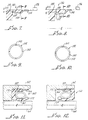
- Figure 8 shows a further rotary cartridge seal embodiment 130 in accordance with the present invention including a plastic ring 132 and metal retainer 134 for insertion into a housing 136.
- a thin cantilever section 140 of the metallic retainer 132 is provided with an arrowhead shaped head 142, which is forced into intimate contact with a correspondingly shaped groove 144 to create axial locking between the plastic ring 132 and the metal retainer 134.
- the arrowhead 142 may have a dovetail design as shown in Figure 6 to improve locking action. Radial interference is provided between the seal OD and the housing 136 to improve seal performance.
- Improved flexibility of the cantilever portion 120 of the metallic retainer 114 shown in Figure 7 may be obtained by providing longitudinal slots 150 as shown in Figure 9. Slots 150 provide for added deflection and hence greater flexibility of the metal retainer 114 in order to accommodate larger temperature ranges as may be desired.
- the plastic ring 132 may include a plurality of flats 154 on a circumference 156 in order to prevent rotation of the plastic ring 132 during operation.
- the cold flow characteristics of the PTFE material utilized in the ring 132 enable material to flow into the flats thereby preventing rotation of the plastic 132.
- FIG. 11 and 12 Yet another embodiment 160 of the present invention is shown in Figures 11 and 12.
- the rotary cartridge seal 160 design enables the cartridge seal 160 to be inserted and utilized between a housing 162 and shaft 164 in opposite directions as are correspondingly represented in Figures 11 and 12.
- a metal retainer 166 is similar to the retainer hereinabove described in connection with retainer 30 shown in Figure 1, and the plastic ring 170 having a lip 172 is similar in design and function to the plastic ring 62 and lip 66 as described in connection with Figure 3.
- a plastic ring 170 is U-shaped and a spring 180 is disposed therein between a lip 172 and the metal retainer 166 with the spring 180 being disposed in the position bearing against a metallic retainer front portion 182. This configuration provides for increased sealing ability.
- sealing lip designs indicated in Figures 1 and 4 may be used in place of the designs indicated in Figures 11 and 12.
- rotary cartridge seals, 10, 60, 78, 90, 110, 130, and 160 provide for an assembly that creates residual stresses to maintain intimate contact between the plastic rings and metal retainers within a specific temperature ranges, for example, between about -20° and about 100°C. Intimate contact between seal surfaces take up for variations that may occur to the PTFE material during usage especially at elevated temperatures. Specifically described dimensions and configurations with regard to clearances hereinabove discussed, control the cold flow of the PTFE material, and limit the shrinkage thereof, while maintaining residual stress in order to maintain intimate contact between the plastic rings and corresponding metallic retainers.
Landscapes
- Engineering & Computer Science (AREA)
- General Engineering & Computer Science (AREA)
- Mechanical Engineering (AREA)
- Sealing With Elastic Sealing Lips (AREA)
- Sealing Devices (AREA)
- Closures For Containers (AREA)
Claims (15)
- Joint d'étanchéité rotatif de cartouche comprenant:une bague en matière plastique apte fluer à froid comportant des moyens formant corps destinée s'appliquer de façon étanche dans un alésage de boítier, et des moyens formant lèvre destinés à s'appliquer de façon étanche contre un arbre tournant à l'intérieur dudit alésage de boítier;des moyens séparables de retenue formés d'un métal servant à fixer ladite bague en matière plastique dans ledit alésage de boítier et autour dudit arbre, lesdits moyens séparables de retenue formés d'un métal possédant une surface de révolution comportant une partie arrière possédant un rayon convenant pour le montage à force dans ledit alésage de boítier et une partie avant ayant un rayon plus faible et se terminant sous la forme d'un anneau; etdes moyens définissant une gorge intérieure dans lesdits moyens formant corps et destinés à coopérer avec la bague située dans les moyens formant corps pour verrouiller entre eux la bague en matière plastique et les moyens formant dispositif de retenue formés d'un métal, avec une contrainte résiduelle à la fois dans les directions à la fois axiale et radiale à l'intérieur de la bague en matière plastique en raison des dimensions et de la forme de la gorge et de la bague.
- Joint d'étanchéité selon la revendication 1, dans lequel ladite gorge intérieur possède un rayon supérieur à la bague et la partie saillante avant du dispositif de retenue formé d'un métal, au voisinage de la bague, possède un rayon extérieur inférieur à un rayon intérieur de contact des moyens formant corps de la bague en matière plastique, adjacente à ladite gorge intérieure de manière à maintenir la contrainte radiale dans ledit corps de la bague en matière plastique.
- Joint d'étanchéité selon la revendication 2, dans lequel une largeur desdits moyens formant gorge est supérieure à une largeur de la bague, mais est inférieure à une largeur nécessaire pour recevoir une matière plastique en excès refoulée à force par la contrainte radiale due au fluage à froid dans lesdits moyens formant gorge, ce qui maintient la contrainte axiale dans la bague en matière plastique.
- Joint d'étanchéité selon la revendication 3, dans lequel lesdits moyens formant lèvre comprennent des moyens formant tête disposés sur une extrémité desdits moyens formant lèvre, pour coopérer avec l'arbre.
- Joint d'étanchéité selon la revendication 4, dans lequel ladite bague en matière plastique comprend en outre des moyens pour définir une seconde gorge adjacente auxdits moyens formant lèvre, et des moyens formant ressort, disposés dans ladite seconde gorge pour solliciter lesdits moyens formant lèvre contre ledit arbre.
- Joint d'étanchéité selon la revendication 5, dans lequel des moyens formant bague formée d'un métal comprennent des moyens formant épaulement qui s'étendent radialement vers l'intérieur et sont destinés à faciliter la séparation des moyens formant dispositif de retenue formé d'un métal à partir dudit alésage du boítier.
- Joint d'étanchéité selon la revendication 6, dans lequel la bague en matière plastique comprend des moyens définissant des méplats sur une surface extérieure de la bague, afin d'empêcher le mouvement de rotation de la bague en matière plastique.
- Joint d'étanchéité rotatif de cartouche, comprenant:une bague en matière plastique apte à fluer à froid comportant des moyens formant corps destinés s'appliquer de façon étanche dans un alésage de boítier, et des moyens formant lèvre destinés à s'appliquer de façon étanche contre un arbre tournant à l'intérieur dudit alésage de boítier;des moyens séparables formant dispositif de retenue formés d'un métal servant à fixer ladite bague en matière plastique dans ledit alésage de boítier et autour dudit arbre, lesdits moyens séparables formant dispositif de retenue formés d'un métal possédant une surface de révolution comportant une partie arrière possédant un diamètre convenant pour le montage à force dans ledit alésage de boítier et une partie avant ayant un diamètre plus faible et se terminant sous la forme d'un anneau; etdes moyens définissant une gorge intérieure dans lesdits moyens formant corps et destinés à coopérer avec la bague située dans les moyens formant corps pour verrouiller la bague en matière plastique et les moyens formant dispositif de retenue formés d'un métal l'un avec l'autre, avec une contrainte résiduelle à la fois dans une direction axiale à l'intérieur de la bague en matière plastique en raison des dimensions et de la forme de la gorge et de la bague.
- Joint d'étanchéité selon la revendication 8, dans lequel ladite gorge intérieure possède un diamètre supérieur à celui de la bague, et dans lequel une largeur desdits moyens formant gorge est inférieure à une largeur de la bague de manière à maintenir une contrainte axiale dans le corps en matière plastique.
- Joint d'étanchéité selon la revendication 9, dans lequel ladite gorge intérieure possède une forme générale rectangulaire comportant une paroi latérale en queue d'aronde tournée vers un côté arrière de ladite bague.
- Joint d'étanchéité selon la revendication 9, dans lequel la partie avant des moyens formant dispositif de retenue formés d'un métal inclue des moyens définissant une section transversale mince dans la partie avant, de manière à appliquer une force radiale aux moyens formant corps de la bague en matière plastique de manière à y provoquer une contrainte radiale.
- Joint d'étanchéité selon la revendication 11, dans lequel la partie avant des moyens formant dispositif de retenue formés d'un métal inclut des moyens, qui définissent de gorges longitudinales sur une surface intérieure de ces moyens, pour produire une contrainte radiale accrue dans les moyens formant corps de la bague en matière plastique.
- Joint d'étanchéité selon la revendication 12, dans lequel la bague en matière plastique contient des moyens définissant des méplats sur une surface extérieure de la bague, pour empêcher un mouvement de rotation de la bague en matière plastique.
- Joint d'étanchéité selon la revendication 11, dans lequel ladite bague en matière plastique possède une forme en U et comprenant en outre les moyens formant ressort, disposés entre lesdits moyens formant lèvre et lesdits moyens formant corps pour solliciter lesdits moyens formant lèvre contre ledit arbre, lesdits moyens formant ressort étant disposés dans une position en appui contre la partie avant des moyens formant dispositif de retenue formés d'un métal.
- Joint d'étanchéité selon la revendication 1, dans lequel ladite bague en matière plastique est en forme de U, et comprenant en outre des moyens formant ressort, disposés entre lesdits moyens formant lèvre et lesdits moyens formant corps pour solliciter lesdits moyens formant lèvre contre ledit arbre, lesdits moyens formant ressort étant disposés dans une position en appui contre la partie avant des moyens de retenue formés d'un métal.
Applications Claiming Priority (2)
| Application Number | Priority Date | Filing Date | Title |
|---|---|---|---|
| US09/037,324 US6050572A (en) | 1998-03-09 | 1998-03-09 | Rotary cartridge seals with retainer |
| US37324 | 1998-03-09 |
Publications (3)
| Publication Number | Publication Date |
|---|---|
| EP0942209A2 EP0942209A2 (fr) | 1999-09-15 |
| EP0942209A3 EP0942209A3 (fr) | 2000-07-12 |
| EP0942209B1 true EP0942209B1 (fr) | 2004-01-28 |
Family
ID=21893732
Family Applications (1)
| Application Number | Title | Priority Date | Filing Date |
|---|---|---|---|
| EP99103496A Expired - Lifetime EP0942209B1 (fr) | 1998-03-09 | 1999-02-24 | Cartouche d'étanchéité munie d'un dispositif de retenue |
Country Status (4)
| Country | Link |
|---|---|
| US (3) | US6050572A (fr) |
| EP (1) | EP0942209B1 (fr) |
| JP (1) | JP4873767B2 (fr) |
| DE (1) | DE69914392T2 (fr) |
Families Citing this family (117)
| Publication number | Priority date | Publication date | Assignee | Title |
|---|---|---|---|---|
| FR2767374B1 (fr) * | 1997-08-13 | 1999-09-17 | Hispano Suiza Sa | Agencement d'etancheite pour un bout d'arbre |
| US6186507B1 (en) | 1997-09-25 | 2001-02-13 | Michael R. Oldenburg | Retrofittable severe duty seal for a shaft |
| US20020011710A1 (en) * | 1997-09-25 | 2002-01-31 | Oldenburg Michael R. | Retrofittable severe duty seal for a shaft |
| JP2002115762A (ja) * | 2000-04-28 | 2002-04-19 | Nok Corp | 密封装置 |
| DE10028159A1 (de) * | 2000-06-07 | 2001-12-13 | Mann & Hummel Filter | Ölmodul für eine Brennkraftmaschine |
| SE521175C2 (sv) | 2001-03-07 | 2003-10-07 | Metso Paper Inc | Axeltätning innefattande ett fjädrande ringelement anordnat att inte komma i kontakt med ett medium i ett mediumutrymme samt att påverka en tätningsläpp i rikting mot en roterbar yta |
| EP1379798A2 (fr) * | 2001-03-28 | 2004-01-14 | Balseal Engineering Co., Inc. | Systeme d'etancheite assurant une isolation contre des milieux |
| EP1461548A4 (fr) * | 2001-04-18 | 2007-03-14 | Bal Seal Engineering Co | Joint anti-rupture incorpore pour fluides ou gaz |
| US6626438B2 (en) | 2001-06-04 | 2003-09-30 | Hps, Inc. | Seal assembly for telescopic hydraulic cylinder |
| JP2003074491A (ja) * | 2001-09-04 | 2003-03-12 | Nsk Ltd | ウォータポンプ用シール装置とウォータポンプ用回転支持装置とウォータポンプ |
| US6692007B2 (en) | 2001-10-31 | 2004-02-17 | Transcom, Inc. | Seal for a shaft |
| US6620361B1 (en) | 2002-07-09 | 2003-09-16 | Federal-Mogul World Wide, Inc. | Method of manufacturing a composite seal |
| US6918595B2 (en) | 2002-11-22 | 2005-07-19 | Dionex Corporation | Seal for high-pressure pumping system |
| US20040256811A1 (en) * | 2002-11-22 | 2004-12-23 | Proper George N. | Seal for high-pressure pumping system |
| EP1433988B1 (fr) * | 2002-12-24 | 2005-12-14 | Techspace Aero S.A. | Vanne de régulation |
| US7344140B2 (en) * | 2003-02-27 | 2008-03-18 | Eagle Industry Co., Ltd. | Lip-type seal |
| US7110827B2 (en) * | 2003-04-25 | 2006-09-19 | Medtronic, Inc. | Electrical connectors for medical lead having weld-less wiring connection |
| US8078280B2 (en) * | 2003-04-25 | 2011-12-13 | Medtronic, Inc. | Implantable biomedical electrical connectors having integral side and inner walls |
| US7118114B2 (en) * | 2003-05-15 | 2006-10-10 | Woodward Governor Company | Dynamic sealing arrangement for movable shaft |
| US7004477B2 (en) * | 2003-05-21 | 2006-02-28 | Freudenberg-Nok General Partnership | Reduced load gasket |
| US6905144B2 (en) * | 2003-07-02 | 2005-06-14 | Delaware Capital Formation | Spring-loaded ‘L’-shaped seal ring |
| JP4537033B2 (ja) * | 2003-10-16 | 2010-09-01 | 株式会社カワサキプレシジョンマシナリ | ガス用シール構造 |
| DE102004004938B4 (de) * | 2004-01-31 | 2007-11-29 | Ab Skf | Dichtungsanordnung |
| US7021632B2 (en) * | 2004-03-04 | 2006-04-04 | Flowserve Management Company | Self-energized gasket and manufacturing method therefor |
| US7147229B2 (en) * | 2004-03-15 | 2006-12-12 | Federal Mogul World Wide Inc. | Shaft seal assembly with retaining ring and washer |
| US20060022414A1 (en) * | 2004-07-30 | 2006-02-02 | Balsells Peter J | Rotary cartridge seals with composite retainer |
| WO2006130704A2 (fr) * | 2005-05-31 | 2006-12-07 | Dewalch Technologies, Inc. | Appareil et procede de verrouillage |
| US20070120084A1 (en) * | 2005-11-29 | 2007-05-31 | Stumbo Steven C | Fully independent, redundant fluid energized sealing solution with secondary containment |
| US7426936B2 (en) * | 2005-11-29 | 2008-09-23 | Woodward Governor Company | Fully independent, redundant fluid energized sealing solution with secondary containment |
| JP5045869B2 (ja) * | 2005-12-08 | 2012-10-10 | Nok株式会社 | リップタイプシール |
| CA2659010C (fr) * | 2006-08-03 | 2012-10-09 | Welldynamics, Inc. | Scellement metal-metal pour outils de fond de puits |
| US20080106040A1 (en) * | 2006-08-10 | 2008-05-08 | Zielke Clyde R | Multimember Extended Range Compressible Seal |
| WO2008154490A1 (fr) * | 2007-06-07 | 2008-12-18 | Saint-Gobain Performance Plastics Corporation | Joint de face et méthode de fabrication |
| US8328202B2 (en) | 2007-12-07 | 2012-12-11 | Bal Seal Engineering, Inc. | Seal assembly for high pressure dynamic and static services |
| EP2238380B1 (fr) * | 2008-02-04 | 2016-04-13 | Welldynamics, Inc. | Joint d'étanchéité métal-métal composite excité |
| US7908934B2 (en) * | 2008-02-29 | 2011-03-22 | Dionex Corporation | Valve assembly |
| NL1036567A1 (nl) | 2008-03-28 | 2009-09-29 | Asml Netherlands Bv | A lithographic apparatus and a vacuum chamber. |
| US8096559B2 (en) | 2008-05-23 | 2012-01-17 | Bal Seal Engineering, Inc. | Rotary seals |
| GB0814616D0 (en) * | 2008-08-11 | 2008-09-17 | Crane John Uk Ltd | Improvements in and relating to spring energised plastic seals |
| EP2181663B1 (fr) * | 2008-10-29 | 2016-05-11 | Arthrex, Inc. | Système d'étanchéité pour pièces à main médicales/dentaires |
| US20100107829A1 (en) * | 2008-10-30 | 2010-05-06 | Nemcomed, Inc. | Torque limiting driver |
| WO2010067540A1 (fr) * | 2008-12-10 | 2010-06-17 | 株式会社アルバック | Mécanisme d'étanchéité et dispositif de traitement |
| JP5394507B2 (ja) * | 2009-03-06 | 2014-01-22 | サン−ゴバン パフォーマンス プラスティックス コーポレイション | 重ね合わせ型導電性ヘリカルスプリング |
| US8544850B2 (en) * | 2009-03-23 | 2013-10-01 | Bal Seal Engineering, Inc. | Seal assemblies for movable and static shafts |
| US10247307B2 (en) | 2009-03-23 | 2019-04-02 | Bal Seal Engineering, Inc. | Interlocking composite seals |
| JP2010286014A (ja) * | 2009-06-09 | 2010-12-24 | Nok Corp | 油圧シリンダ |
| US10520091B2 (en) | 2009-07-08 | 2019-12-31 | Bal Seal Engineering, Inc. | Double direction seal with locking |
| US8684362B2 (en) | 2009-08-12 | 2014-04-01 | Bal Seal Engineering, Inc. | Cartridge seal assemblies and associated methods |
| DE102009043059B4 (de) * | 2009-09-28 | 2017-02-02 | Sew-Eurodrive Gmbh & Co Kg | Anordnung zum Abdichten einer Welle und Verfahren zum Herstellen einer Anordnung zum Abdichten einer Welle |
| KR101421431B1 (ko) * | 2009-10-02 | 2014-07-22 | 생-고뱅 퍼포먼스 플라스틱스 코포레이션 | 모듈형 중합체 emi/rfi 씰 |
| CN101705997A (zh) * | 2009-11-30 | 2010-05-12 | 三一重型装备有限公司 | 动密封装置及具有该装置的轮边减速机 |
| WO2011087585A1 (fr) * | 2010-01-14 | 2011-07-21 | Carrier Corporation | Joint étanche à l'huile pour compresseur de fluide frigorigène à mouvement alternatif |
| US9403022B2 (en) * | 2010-01-29 | 2016-08-02 | Medtronic, Inc. | Header assembly for implantable medical device |
| DE102010018421B4 (de) * | 2010-04-27 | 2016-06-09 | Hosokawa Alpine Aktiengesellschaft | Doppelwellenanordnung mit verstellbarem Achsabstand und verbesserter Dichtungseinheit |
| GB201021266D0 (en) * | 2010-12-14 | 2011-01-26 | Crane John Uk Ltd | Seals |
| JP5729548B2 (ja) * | 2011-02-17 | 2015-06-03 | 東洋製罐株式会社 | シール装置 |
| JP6034808B2 (ja) | 2011-03-10 | 2016-11-30 | ウオーターズ・テクノロジーズ・コーポレイシヨン | 往復及び回転用途用のシールアセンブリ |
| US8428724B2 (en) | 2011-03-11 | 2013-04-23 | Greatbatch Ltd. | Low insertion force electrical connector for implantable medical devices |
| DE102011018584A1 (de) * | 2011-04-11 | 2012-10-11 | Blohm + Voss Industries Gmbh | Dichtung zum Abdichten von Wellen |
| US10125872B2 (en) | 2011-08-18 | 2018-11-13 | Bal Seal Engineering, Inc. | Reciprocating seal for high pulsating pressure |
| US9194498B2 (en) | 2012-08-23 | 2015-11-24 | Eagle Industry Co., Ltd. | Sealing device |
| WO2014120310A2 (fr) * | 2012-11-02 | 2014-08-07 | Metallic Hi Temperature Seal Systems, Llc. | Ensemble joint d'étanchéité haute température |
| ES2467490B1 (es) * | 2012-11-12 | 2015-03-24 | Talleres Gilabert Sorribes, S.L. | Dispositivo de sellado hermético para válvulas industriales |
| US9388890B2 (en) * | 2013-01-07 | 2016-07-12 | Trelleborg Sealing Solutions Us, Inc. | Ball screw seal |
| EP2971879B1 (fr) * | 2013-03-15 | 2018-04-25 | Bal Seal Engineering, Inc. | Joints à lèvre haute pression à propriétés anti-extrusion et anti-grippage et procédés associés |
| US9228659B2 (en) * | 2013-05-31 | 2016-01-05 | Aktiebolaget Skf | Seal with replaceable lip |
| US10260639B2 (en) | 2013-06-10 | 2019-04-16 | Fisher Controls International Llc | Actuator bushings having integral seals |
| US10263368B2 (en) * | 2013-06-25 | 2019-04-16 | Bal Seal Engineering, Inc. | Electrical contacts with electrically conductive springs |
| US9194497B2 (en) * | 2013-09-03 | 2015-11-24 | Bal Seal Engineering, Inc. | Elastic seals with dynamic lips and related methods |
| US9963395B2 (en) | 2013-12-11 | 2018-05-08 | Baker Hughes, A Ge Company, Llc | Methods of making carbon composites |
| JP6314487B2 (ja) * | 2014-01-16 | 2018-04-25 | Nok株式会社 | 密封装置 |
| US10598241B2 (en) | 2014-02-26 | 2020-03-24 | Bal Seal Engineering, Inc. | Multi deflection canted coil springs and related methods |
| US20160146351A1 (en) * | 2014-06-23 | 2016-05-26 | Robert Janian | Rosette lipseal |
| WO2016009235A1 (fr) | 2014-07-18 | 2016-01-21 | FAZEKAS, Gábor | Joint d'étanchéité et procédé de fabrication pour ce dernier |
| US9325012B1 (en) | 2014-09-17 | 2016-04-26 | Baker Hughes Incorporated | Carbon composites |
| US10315922B2 (en) | 2014-09-29 | 2019-06-11 | Baker Hughes, A Ge Company, Llc | Carbon composites and methods of manufacture |
| US10480288B2 (en) | 2014-10-15 | 2019-11-19 | Baker Hughes, A Ge Company, Llc | Articles containing carbon composites and methods of manufacture |
| US9962903B2 (en) | 2014-11-13 | 2018-05-08 | Baker Hughes, A Ge Company, Llc | Reinforced composites, methods of manufacture, and articles therefrom |
| US9745451B2 (en) | 2014-11-17 | 2017-08-29 | Baker Hughes Incorporated | Swellable compositions, articles formed therefrom, and methods of manufacture thereof |
| US11097511B2 (en) | 2014-11-18 | 2021-08-24 | Baker Hughes, A Ge Company, Llc | Methods of forming polymer coatings on metallic substrates |
| US9714709B2 (en) | 2014-11-25 | 2017-07-25 | Baker Hughes Incorporated | Functionally graded articles and methods of manufacture |
| US10300627B2 (en) | 2014-11-25 | 2019-05-28 | Baker Hughes, A Ge Company, Llc | Method of forming a flexible carbon composite self-lubricating seal |
| US9726300B2 (en) * | 2014-11-25 | 2017-08-08 | Baker Hughes Incorporated | Self-lubricating flexible carbon composite seal |
| DE102014225932A1 (de) * | 2014-12-15 | 2016-06-16 | Elringklinger Ag | Dichtungsanordnung und Verfahren zur Herstellung einer Dichtungsanordnung |
| US10184564B2 (en) * | 2015-02-02 | 2019-01-22 | Bal Seal Engineering, Inc. | Seal assemblies and related methods |
| CN104595493A (zh) * | 2015-02-10 | 2015-05-06 | 烟台杰瑞石油装备技术有限公司 | 密封装置及其密封圈 |
| WO2016179008A1 (fr) * | 2015-05-01 | 2016-11-10 | Saint-Gobain Performance Plastics Corporation | Joints d'étanchéité |
| US9840887B2 (en) | 2015-05-13 | 2017-12-12 | Baker Hughes Incorporated | Wear-resistant and self-lubricant bore receptacle packoff tool |
| WO2017023251A1 (fr) * | 2015-07-31 | 2017-02-09 | Trelleborg Sealing Solutions Us, Inc. | Joint d'étanchéité haute-pression |
| US10117366B2 (en) | 2015-12-14 | 2018-10-30 | Bal Seal Engineering, Inc. | Spring energized seals and related methods |
| EP3217046B1 (fr) | 2016-03-07 | 2024-05-01 | Bal Seal Engineering, LLC | Ensembles et procédés associés |
| WO2017163992A1 (fr) * | 2016-03-22 | 2017-09-28 | Nok株式会社 | Dispositif d'étanchéité |
| US10125274B2 (en) | 2016-05-03 | 2018-11-13 | Baker Hughes, A Ge Company, Llc | Coatings containing carbon composite fillers and methods of manufacture |
| US10451061B2 (en) * | 2016-05-06 | 2019-10-22 | Ingersoll-Rand Company | Compressor having non-contact and contact seals |
| US10344559B2 (en) | 2016-05-26 | 2019-07-09 | Baker Hughes, A Ge Company, Llc | High temperature high pressure seal for downhole chemical injection applications |
| US10460977B2 (en) | 2016-09-29 | 2019-10-29 | Lam Research Corporation | Lift pin holder with spring retention for substrate processing systems |
| EP3312482B1 (fr) | 2016-10-24 | 2023-09-13 | Bal Seal Engineering, LLC | Ensembles d'étanchéité pour températures extrêmes et procédés associés |
| EP3315829B1 (fr) * | 2016-10-31 | 2020-11-25 | Bal Seal Engineering, LLC | Joints flottants axiaux et radiaux |
| EP3726103B1 (fr) | 2017-03-16 | 2024-02-21 | Bal Seal Engineering, LLC | Ressorts en v, joints avec ressorts en v et procédés associés |
| US10604995B2 (en) * | 2017-06-22 | 2020-03-31 | Sejong Pharmatech Co., Ltd. | Sealing door and method of forming channel |
| EP3456428B1 (fr) | 2017-08-30 | 2023-08-16 | Bal Seal Engineering, LLC | Extrémités du fil de ressort pour faciliter le soudage |
| CN107575381A (zh) * | 2017-09-04 | 2018-01-12 | 珠海格力节能环保制冷技术研究中心有限公司 | 涡旋压缩机及空调器 |
| US11353079B2 (en) | 2017-10-05 | 2022-06-07 | Bal Seal Engineering, Llc | Spring assemblies, applications of spring assemblies, and related methods |
| EP3514380A1 (fr) * | 2018-01-23 | 2019-07-24 | Maximator Gmbh | Compresseurs et procédé de compression d'un milieu de travail |
| DE102018201030A1 (de) | 2018-01-24 | 2019-07-25 | Kardion Gmbh | Magnetkuppelelement mit magnetischer Lagerungsfunktion |
| DE102018105913B4 (de) * | 2018-03-14 | 2021-01-14 | Carl Freudenberg Kg | Dichtring |
| EP3567285A1 (fr) * | 2018-05-08 | 2019-11-13 | Bal Seal Engineering, Inc. | Ensembles joint et procédés associés |
| DE102018211327A1 (de) | 2018-07-10 | 2020-01-16 | Kardion Gmbh | Laufrad für ein implantierbares, vaskuläres Unterstützungssystem |
| GB2580718B (en) | 2019-01-17 | 2023-02-08 | Ntdrill Holdings Llc | Rotating control device with multiple seal cartridge |
| US11028933B2 (en) | 2019-01-22 | 2021-06-08 | Emerson Vulcan Holding Llc | Valve seal assembly |
| JP2022524309A (ja) * | 2019-03-20 | 2022-05-02 | サン-ゴバン パフォーマンス プラスティックス コーポレイション | シール |
| US11788627B1 (en) * | 2019-05-24 | 2023-10-17 | Bae Systems Information And Electronic Systems Integration Inc. | Seal arrangement and undersea high-pressure shaft seal cartridge for underwater vehicles |
| DE102020102474A1 (de) | 2020-01-31 | 2021-08-05 | Kardion Gmbh | Pumpe zum Fördern eines Fluids und Verfahren zum Herstellen einer Pumpe |
| US11618528B2 (en) * | 2020-05-19 | 2023-04-04 | Shimano Inc. | Piston assembly for human-powered vehicle |
| US11940049B1 (en) * | 2022-11-01 | 2024-03-26 | Bal Seal Engineering, Llc | Lip seals and related methods |
| US11746906B1 (en) | 2022-11-01 | 2023-09-05 | Bal Seal Engineering, Llc | Lip seals and related methods |
| US20240141995A1 (en) * | 2022-11-01 | 2024-05-02 | Bal Seal Engineering, Llc | Lip seals and related methods |
Family Cites Families (29)
| Publication number | Priority date | Publication date | Assignee | Title |
|---|---|---|---|---|
| US1950852A (en) * | 1932-03-21 | 1934-03-13 | Eisemann Magneto Corp | Dust seal |
| US2568056A (en) * | 1947-02-11 | 1951-09-18 | Thompson Tool Company | Bearing seal |
| US3037781A (en) * | 1958-05-19 | 1962-06-05 | Renault | Plunger and rod packings |
| US3188098A (en) * | 1962-12-10 | 1965-06-08 | Robert T Skinner | Flexible seal |
| SE333279B (sv) * | 1969-06-30 | 1971-03-08 | Skf Svenska Kullagerfab Ab | Stoed-och taetning foer rullningslager |
| US3829106A (en) * | 1972-12-04 | 1974-08-13 | Crane Packing Co | High pressure lip seal |
| JPS49104054A (fr) * | 1973-02-13 | 1974-10-02 | ||
| GB1467640A (en) * | 1973-11-07 | 1977-03-16 | Girling Ltd | Piston and seal assemblies |
| US4053166A (en) * | 1975-12-08 | 1977-10-11 | Halogen Insulator & Seal Corporation | Two-piece seal |
| DE2610584C3 (de) * | 1976-03-13 | 1978-12-14 | Fa. Carl Freudenberg, 6940 Weinheim | Selbstarretierender Dichtring |
| DE2743501C3 (de) * | 1977-09-28 | 1981-01-08 | Fa. Carl Freudenberg, 6940 Weinheim | Dichtring |
| JPS5937269B2 (ja) * | 1979-05-28 | 1984-09-08 | アイシン精機株式会社 | バキユ−ム式ブ−スタのシ−ル装置 |
| IT7953743V0 (it) * | 1979-11-14 | 1979-11-14 | Fiat Trattori Spa | Dispositivo di tenuta utilizzabile particolarmente per barre flessibili dinamometriche associate al sollevatore idraulico di trattori agricoli |
| JPS6135268A (ja) * | 1984-07-27 | 1986-02-19 | Toshiba Corp | 画像形成装置 |
| JPS6152764A (ja) * | 1984-08-22 | 1986-03-15 | Hitachi Ltd | デバイスインタフエ−スのピン番号変更方式 |
| JP2555588B2 (ja) * | 1987-03-25 | 1996-11-20 | 大豊工業株式会社 | タ−ボチヤ−ジヤ用リツプシ−ル装置 |
| JP2626072B2 (ja) * | 1989-07-20 | 1997-07-02 | 松下電器産業株式会社 | 信号生成回路 |
| US5062648A (en) * | 1989-09-26 | 1991-11-05 | Interventional Technologies, Inc. | Seal for rotating torque tube with seal valve |
| JPH03121267A (ja) * | 1989-10-03 | 1991-05-23 | Yanmar Diesel Engine Co Ltd | ディーゼルエンジンの始動装置 |
| US5269536A (en) * | 1991-04-15 | 1993-12-14 | Nok Corporation | Sealing device |
| US5299811A (en) * | 1992-12-23 | 1994-04-05 | Siemens Automotive Limited | Seal member mounted in housing pocket by resilient retaining member |
| DE4401526C1 (de) * | 1994-01-20 | 1994-12-15 | Wieland Werke Ag | Gleitlager mit integrierter Lippendichtung |
| US5813676A (en) * | 1995-12-18 | 1998-09-29 | Dana Corporation | Oil seal extender |
| JPH09210214A (ja) * | 1996-01-30 | 1997-08-12 | Nok Corp | 密封装置 |
| DE19609472A1 (de) * | 1996-03-04 | 1997-09-11 | Schaeffler Waelzlager Kg | Ringkolbendichtung für ein hydraulisch betätigbares Ausrücksystem |
| US5797602A (en) * | 1996-10-10 | 1998-08-25 | Pac-Seal Inc. International | Mechanical seal for water pump of heavy duty vehicle |
| US5855375A (en) * | 1997-05-12 | 1999-01-05 | General Motors Corporation | Seal for steering assist fluid motor |
| US5979904A (en) * | 1997-12-12 | 1999-11-09 | Bal Seal Engineering Company, Inc. | Rotary reciprocating seals with exterior metal band |
| US5984316A (en) * | 1997-12-12 | 1999-11-16 | Bal Seal Engineering Company, Inc. | Rotary reciprocating seals with internal metal band |
-
1998
- 1998-03-09 US US09/037,324 patent/US6050572A/en not_active Expired - Lifetime
-
1999
- 1999-02-24 EP EP99103496A patent/EP0942209B1/fr not_active Expired - Lifetime
- 1999-02-24 DE DE69914392T patent/DE69914392T2/de not_active Expired - Lifetime
- 1999-03-04 JP JP05697199A patent/JP4873767B2/ja not_active Expired - Lifetime
-
2000
- 2000-02-11 US US09/503,093 patent/US6264205B1/en not_active Expired - Lifetime
- 2000-03-15 US US09/526,427 patent/US6161838A/en not_active Expired - Lifetime
Also Published As
| Publication number | Publication date |
|---|---|
| JP4873767B2 (ja) | 2012-02-08 |
| US6264205B1 (en) | 2001-07-24 |
| DE69914392D1 (de) | 2004-03-04 |
| JPH11315933A (ja) | 1999-11-16 |
| DE69914392T2 (de) | 2004-12-09 |
| US6050572A (en) | 2000-04-18 |
| US6161838A (en) | 2000-12-19 |
| EP0942209A2 (fr) | 1999-09-15 |
| EP0942209A3 (fr) | 2000-07-12 |
Similar Documents
| Publication | Publication Date | Title |
|---|---|---|
| EP0942209B1 (fr) | Cartouche d'étanchéité munie d'un dispositif de retenue | |
| US20060022414A1 (en) | Rotary cartridge seals with composite retainer | |
| US5873576A (en) | Skew and twist resistant hydrodynamic rotary shaft seal | |
| US7427070B2 (en) | Unitizing element and method for assembling a seal | |
| US5984316A (en) | Rotary reciprocating seals with internal metal band | |
| US5979904A (en) | Rotary reciprocating seals with exterior metal band | |
| US20010020770A1 (en) | Hydrodynamic rotary seal with varying slope | |
| US20050212218A1 (en) | Cover seals with latching locking features | |
| CA2233100C (fr) | Amelioration dans les joints d'etancheite en plastique a ressort | |
| US8651496B2 (en) | Seal | |
| CA2176751C (fr) | Etancheite pour arbre usine, encastre dans un manchon en elastomere | |
| US3377075A (en) | Rotating shaft seal retainer | |
| US6688602B2 (en) | Shaft sealing mechanism of compressor with mechanical seal | |
| CN112524250A (zh) | 针对低温应用优化的具有唇的密封部 |
Legal Events
| Date | Code | Title | Description |
|---|---|---|---|
| PUAI | Public reference made under article 153(3) epc to a published international application that has entered the european phase |
Free format text: ORIGINAL CODE: 0009012 |
|
| AK | Designated contracting states |
Kind code of ref document: A2 Designated state(s): DE FR GB |
|
| AX | Request for extension of the european patent |
Free format text: AL;LT;LV;MK;RO;SI |
|
| PUAL | Search report despatched |
Free format text: ORIGINAL CODE: 0009013 |
|
| AK | Designated contracting states |
Kind code of ref document: A3 Designated state(s): AT BE CH CY DE DK ES FI FR GB GR IE IT LI LU MC NL PT SE |
|
| AX | Request for extension of the european patent |
Free format text: AL;LT;LV;MK;RO;SI |
|
| 17P | Request for examination filed |
Effective date: 20000818 |
|
| AKX | Designation fees paid |
Free format text: DE FR GB |
|
| GRAP | Despatch of communication of intention to grant a patent |
Free format text: ORIGINAL CODE: EPIDOSNIGR1 |
|
| GRAS | Grant fee paid |
Free format text: ORIGINAL CODE: EPIDOSNIGR3 |
|
| GRAA | (expected) grant |
Free format text: ORIGINAL CODE: 0009210 |
|
| AK | Designated contracting states |
Kind code of ref document: B1 Designated state(s): DE FR GB |
|
| REG | Reference to a national code |
Ref country code: GB Ref legal event code: FG4D |
|
| REF | Corresponds to: |
Ref document number: 69914392 Country of ref document: DE Date of ref document: 20040304 Kind code of ref document: P |
|
| ET | Fr: translation filed | ||
| PLBE | No opposition filed within time limit |
Free format text: ORIGINAL CODE: 0009261 |
|
| STAA | Information on the status of an ep patent application or granted ep patent |
Free format text: STATUS: NO OPPOSITION FILED WITHIN TIME LIMIT |
|
| 26N | No opposition filed |
Effective date: 20041029 |
|
| REG | Reference to a national code |
Ref country code: FR Ref legal event code: PLFP Year of fee payment: 18 |
|
| REG | Reference to a national code |
Ref country code: FR Ref legal event code: PLFP Year of fee payment: 19 |
|
| REG | Reference to a national code |
Ref country code: FR Ref legal event code: PLFP Year of fee payment: 20 |
|
| PGFP | Annual fee paid to national office [announced via postgrant information from national office to epo] |
Ref country code: GB Payment date: 20180221 Year of fee payment: 20 Ref country code: DE Payment date: 20180214 Year of fee payment: 20 |
|
| PGFP | Annual fee paid to national office [announced via postgrant information from national office to epo] |
Ref country code: FR Payment date: 20180111 Year of fee payment: 20 |
|
| REG | Reference to a national code |
Ref country code: DE Ref legal event code: R071 Ref document number: 69914392 Country of ref document: DE |
|
| REG | Reference to a national code |
Ref country code: GB Ref legal event code: PE20 Expiry date: 20190223 |
|
| PG25 | Lapsed in a contracting state [announced via postgrant information from national office to epo] |
Ref country code: GB Free format text: LAPSE BECAUSE OF EXPIRATION OF PROTECTION Effective date: 20190223 |