EP0941794B1 - Bohrwerkzeug - Google Patents
Bohrwerkzeug Download PDFInfo
- Publication number
- EP0941794B1 EP0941794B1 EP99810126A EP99810126A EP0941794B1 EP 0941794 B1 EP0941794 B1 EP 0941794B1 EP 99810126 A EP99810126 A EP 99810126A EP 99810126 A EP99810126 A EP 99810126A EP 0941794 B1 EP0941794 B1 EP 0941794B1
- Authority
- EP
- European Patent Office
- Prior art keywords
- head
- shaft
- drilling tool
- drill head
- duct
- Prior art date
- Legal status (The legal status is an assumption and is not a legal conclusion. Google has not performed a legal analysis and makes no representation as to the accuracy of the status listed.)
- Expired - Lifetime
Links
- 238000005553 drilling Methods 0.000 title claims description 63
- 238000005520 cutting process Methods 0.000 claims description 63
- 239000000463 material Substances 0.000 claims description 12
- 238000005476 soldering Methods 0.000 claims description 7
- 238000003466 welding Methods 0.000 claims description 7
- 230000002093 peripheral effect Effects 0.000 claims description 6
- 239000011435 rock Substances 0.000 claims description 3
- 230000001747 exhibiting effect Effects 0.000 claims 1
- 230000000717 retained effect Effects 0.000 claims 1
- 238000005304 joining Methods 0.000 description 12
- 238000000034 method Methods 0.000 description 8
- 230000008878 coupling Effects 0.000 description 6
- 238000010168 coupling process Methods 0.000 description 6
- 238000005859 coupling reaction Methods 0.000 description 6
- 229910052751 metal Inorganic materials 0.000 description 6
- 239000002184 metal Substances 0.000 description 6
- 238000004519 manufacturing process Methods 0.000 description 5
- 229910000831 Steel Inorganic materials 0.000 description 4
- 239000010959 steel Substances 0.000 description 4
- 238000013461 design Methods 0.000 description 3
- 238000003780 insertion Methods 0.000 description 3
- 230000037431 insertion Effects 0.000 description 3
- 230000000694 effects Effects 0.000 description 2
- 238000011010 flushing procedure Methods 0.000 description 2
- 238000005245 sintering Methods 0.000 description 2
- 206010010774 Constipation Diseases 0.000 description 1
- 238000010009 beating Methods 0.000 description 1
- 230000015556 catabolic process Effects 0.000 description 1
- 238000004140 cleaning Methods 0.000 description 1
- 238000006731 degradation reaction Methods 0.000 description 1
- 238000011161 development Methods 0.000 description 1
- 238000000605 extraction Methods 0.000 description 1
- 239000007788 liquid Substances 0.000 description 1
- 238000005457 optimization Methods 0.000 description 1
- 239000000843 powder Substances 0.000 description 1
- 238000012545 processing Methods 0.000 description 1
- 238000007493 shaping process Methods 0.000 description 1
- 238000010008 shearing Methods 0.000 description 1
- 238000009987 spinning Methods 0.000 description 1
- UONOETXJSWQNOL-UHFFFAOYSA-N tungsten carbide Chemical compound [W+]#[C-] UONOETXJSWQNOL-UHFFFAOYSA-N 0.000 description 1
Images
Classifications
-
- B—PERFORMING OPERATIONS; TRANSPORTING
- B23—MACHINE TOOLS; METAL-WORKING NOT OTHERWISE PROVIDED FOR
- B23Q—DETAILS, COMPONENTS, OR ACCESSORIES FOR MACHINE TOOLS, e.g. ARRANGEMENTS FOR COPYING OR CONTROLLING; MACHINE TOOLS IN GENERAL CHARACTERISED BY THE CONSTRUCTION OF PARTICULAR DETAILS OR COMPONENTS; COMBINATIONS OR ASSOCIATIONS OF METAL-WORKING MACHINES, NOT DIRECTED TO A PARTICULAR RESULT
- B23Q11/00—Accessories fitted to machine tools for keeping tools or parts of the machine in good working condition or for cooling work; Safety devices specially combined with or arranged in, or specially adapted for use in connection with, machine tools
- B23Q11/0042—Devices for removing chips
- B23Q11/0046—Devices for removing chips by sucking
-
- B—PERFORMING OPERATIONS; TRANSPORTING
- B23—MACHINE TOOLS; METAL-WORKING NOT OTHERWISE PROVIDED FOR
- B23B—TURNING; BORING
- B23B51/00—Tools for drilling machines
-
- B—PERFORMING OPERATIONS; TRANSPORTING
- B23—MACHINE TOOLS; METAL-WORKING NOT OTHERWISE PROVIDED FOR
- B23B—TURNING; BORING
- B23B51/00—Tools for drilling machines
- B23B51/06—Drills with lubricating or cooling equipment
-
- B—PERFORMING OPERATIONS; TRANSPORTING
- B23—MACHINE TOOLS; METAL-WORKING NOT OTHERWISE PROVIDED FOR
- B23B—TURNING; BORING
- B23B2251/00—Details of tools for drilling machines
- B23B2251/20—Number of cutting edges
- B23B2251/202—Three cutting edges
-
- Y—GENERAL TAGGING OF NEW TECHNOLOGICAL DEVELOPMENTS; GENERAL TAGGING OF CROSS-SECTIONAL TECHNOLOGIES SPANNING OVER SEVERAL SECTIONS OF THE IPC; TECHNICAL SUBJECTS COVERED BY FORMER USPC CROSS-REFERENCE ART COLLECTIONS [XRACs] AND DIGESTS
- Y10—TECHNICAL SUBJECTS COVERED BY FORMER USPC
- Y10T—TECHNICAL SUBJECTS COVERED BY FORMER US CLASSIFICATION
- Y10T408/00—Cutting by use of rotating axially moving tool
- Y10T408/50—Cutting by use of rotating axially moving tool with product handling or receiving means
-
- Y—GENERAL TAGGING OF NEW TECHNOLOGICAL DEVELOPMENTS; GENERAL TAGGING OF CROSS-SECTIONAL TECHNOLOGIES SPANNING OVER SEVERAL SECTIONS OF THE IPC; TECHNICAL SUBJECTS COVERED BY FORMER USPC CROSS-REFERENCE ART COLLECTIONS [XRACs] AND DIGESTS
- Y10—TECHNICAL SUBJECTS COVERED BY FORMER USPC
- Y10T—TECHNICAL SUBJECTS COVERED BY FORMER US CLASSIFICATION
- Y10T408/00—Cutting by use of rotating axially moving tool
- Y10T408/78—Tool of specific diverse material
-
- Y—GENERAL TAGGING OF NEW TECHNOLOGICAL DEVELOPMENTS; GENERAL TAGGING OF CROSS-SECTIONAL TECHNOLOGIES SPANNING OVER SEVERAL SECTIONS OF THE IPC; TECHNICAL SUBJECTS COVERED BY FORMER USPC CROSS-REFERENCE ART COLLECTIONS [XRACs] AND DIGESTS
- Y10—TECHNICAL SUBJECTS COVERED BY FORMER USPC
- Y10T—TECHNICAL SUBJECTS COVERED BY FORMER US CLASSIFICATION
- Y10T408/00—Cutting by use of rotating axially moving tool
- Y10T408/89—Tool or Tool with support
- Y10T408/907—Tool or Tool with support including detailed shank
Definitions
- the invention relates to a drilling tool according to the preamble of the claim 1, (see for example US 3 767 315).
- suction drills In addition to the well-known drilling tools for drilling holes in rock, Concrete, masonry and the like, in which the removed cuttings by means at least one on the shank of the cutting tool provided with cutting edges spiral helix is removed from the borehole
- suction drills have also been proposed in the past. They consist of a drilling tool equipped with an axial bore, which is connected via an adapter and a coupling part to a vacuum generating device, in particular a device Vacuum cleaner or the like, is connected. Suction drills are said to have a Extraction of the cuttings generated during operation produce a higher drilling performance and lead to better cleaning of the borehole. Such a suction drill is described for example in DE-A-27 56 140.
- This known suction drill has a shaft provided with an axial suction bore, one end of which in an adapter is used, which is surrounded by a rotationally fixed coupling part. At the opposite end of the shaft is a head part with inserted carbide cutting tips removably screwed in.
- the suction hole is with a hole in the Head part in connection, which open on both sides of the cutting tip.
- the suction hole is connected to a vacuum cleaner. During operation, the cuttings created on the cutting edges are removed by the drill head and the suction hole is transported into the vacuum cleaner.
- This known suction drill has an interchangeable head part, which is in the shaft is screwed in. With excessive wear of the inserted in the headboard Carbide cutting tip or if the holes are blocked, the head part be interchangeable. Due to the operation of hammer drills in particular The large single impact energies of the axial impacts become the screw thread very heavily loaded in the shaft and on the head part. It can happen that the Thread is knocked out and the head part is no longer securely attachable. On the other hand, the rotation of the drilling tool in the Operation the screw connection between the head part and the shaft so tight is tightened that if necessary, it is only with great force or even is no longer solvable. The production of this known suction drill also proves to be relatively complex. The production of the axial bore in the exhibits a relatively long steel rod existing high demands on the Manufacturing engineering.
- the shaft of the To manufacture drilling tool from a steel sleeve.
- One end of the sleeve-shaped shaft is connected to an adapter which is surrounded by a rotationally fixed coupling part, to which, for example, a vacuum cleaner can be connected.
- the adapter In axial extension of the The shaft is the adapter with an insertion end for the connection of the drilling tool equipped with a drill.
- the steel sleeve is on its opposite Provide front ends with axial slots that are arranged in a cross shape. In these Axial slots are the cutting edges of a one-piece sintered hard metal cutting cross inserted and fastened.
- the shape of the cutting edges and the inside diameter of the sleeve-shaped shaft are selected so that between the cutting edges and the inner wall of the shaft remain openings which are connected to the axial channel in the shaft.
- the drilling tool known from DE-U-79 08 923 has a relative in the head area low stability.
- the cutting cross sintered in one piece from hard metal, is only in the axial slots are supported by the steel sleeve.
- the one beating while spinning Degradation of the subsurface shear forces must be almost completely by the cutting cross.
- the cutting cross can move out loosen the slot guides or the carbide may even fail come.
- the shape of the cross-shaped blades is chosen such that opening areas between the cutting edges and the inner wall of the shaft remain, which extend in the axial continuation of the axial channel.
- the cutting are therefore formed like strips and have an increasing to the intersection area Height up. In this way, the individual cutting edges in the intersection area form one Cutting tip that bridges the axial channel without any support.
- Operational is the protruding cutting tip of the greatest load from the axial blows subjected. Due to the design of the cutting cross, it can especially in connection with hammer drills with relatively large Single impact energies of the axial impacts occur that are made in one piece Tungsten carbide sintered cutting cross breaks. The cutting and the The inner wall of the sleeve bordered openings are axially oriented. In operation it can occur that the head end of the suction drill completely into the dismantled Immerse cuttings. Then the suction effect is often not enough to do that Vacuum drill cuttings quickly enough and the openings can become blocked.
- US Pat. No. 3,767,315 discloses a drilling tool with a tubular shaft, which has a Has suction openings opening passage known. At the front end a cutting head made of hard metal is attached to the shaft, the Drill head has a cylindrical bore, which positively on the cylinder surface of the tubular shaft and is soldered or welded there. The front one The end of the shaft is tapered towards the through-channel at an angle A of 30 ° partially forms the suction openings.
- the object of the present invention is to overcome these disadvantages of the drilling tools Remedy the state of the art. It is intended to be a drilling tool of the generic type be created that a sleeve-shaped shaft and a completely Cutting material, preferably made of a hard metal, has a sintered drill head.
- the drilling tool should be designed in such a way that the plugging with the Through channel in the shaft communicating suction openings through in operation degraded cuttings is prevented.
- the assembly of the drill head should be simple and can be done reliably.
- the solution to these tasks consists in a drilling tool with the characteristic in Features of claim 1.
- the inventive Drilling tool for drilling holes in rock, concrete, masonry and the like has a tubular shaft which one in suction openings has an opening, axially extending through channel. At one longitudinal end is the tubular shaft with an insertion end for connection to a drill fitted.
- the shaft carries one at the opposite free front end Cutting head, which is made entirely of cutting material, preferably consists of a hard metal.
- the drill head is with the free front end of the pipe shaped shaft essentially butt joined and preferably by welding or soldering connected.
- At least one suction opening is from the mouth of one Head channel formed, which is at least partially bordered by the material of the drill head and its mouth surface at least partially in the peripheral region of the shaft and / or the drill head is arranged.
- the drilling tool has at least one head channel, the mouth surface arranged to a large extent in the peripheral region of the shank and / or the drill head the suction opening cannot clog so easily during operation.
- the mouth of the head channel is located outside the attack of the Cut on the subsurface and do not plunge directly into the excavated cuttings. This prevents the suction opening, for example when still insufficient suction power at the start of the drilling process, which is clogged by the cuttings.
- the suction opening at least partially bordered by the material of the drill head is the same However, the bottom of the borehole is close enough that the vacuum generated during operation means that Drilling cuttings generated during drilling can be reliably removed.
- the side Orientation of the mouth opening to the annular space formed during operation prevents material that has not yet been sufficiently shredded is placed in front of the suction opening and the suction hinders. In this way, only cuttings reach the suction opening, that the cutting edges in the annular space have been ground sufficiently.
- the fixation of the drill head on The front end of the shaft is preferably made by welding or soldering. Both Joining techniques have been tried and tested and guarantee the required hold of the Drill head on the shaft.
- the Head channel in the direction of the jacket of the shaft or to the axial side surface of the Orienting and closing the drill head with the longitudinal axis of the tubular shaft An angle that is less than 90 ° and preferably between 10 ° and 70 °.
- the Head channel is preferably through a material recess in the jacket of the shaft and / or formed in the drill head. This means that it acts as a suction opening Muzzle is formed automatically when joining the head and shaft and can be a further rework is not necessary.
- the recess can be in the front of the Shaft jacket can be provided or it can by a special shape of the Drill head after joining the drill head and the tubular shaft a head channel remain free.
- the head channel can also be achieved by a combination of the two measures be educated.
- the drill head After the drill head is usually in a powder metallurgical Shaping and sintering process is manufactured, there are many freedoms in terms of its shape. It is also possible to cut the material on Drill head after the sintering process, for example by a material-removing processing of the side surface (s) or by creating a or several holes in the drill head.
- the cross-sectional area of the mouth of the head channel is preferably smaller formed as the cross-sectional area of the through channel and is between about 30% and 70% of the cross-sectional area of the through channel.
- Head channels with orifices are preferably the sum of the Cross-sectional areas of all mouth openings smaller than the cross-sectional area of the Through channel.
- the head channel and / or the through channel need not necessarily be one have circular cross section.
- the cross section if necessary also be elliptical, oval, polygonal, etc.
- the need for one of the Circular deviating cross-section may be necessary, for example locally larger joining surface on the shank for the blunt joining process of the drill head be justified.
- the shaft can also have a shape that deviates from the circular shape Have circumferential contour. Due to the largely arbitrary design of the Circumferential contour of the shank can account for optimized shapes of the drill head worn, and at the same time it becomes as large as possible for the joining process Joining area provided.
- the Through channel at least in the front portion of the shaft a polygonal Cross-section and has the drill head on its opposite the cutting edges
- Side an axial extension the circumferential contour of the cross section of the Through channel corresponds at least in some areas.
- the Cross section of the through-channel have the shape of a regular hexagon and the axial extension can be designed as a corresponding hexagon.
- the hexagonal extension is inside the hexagonal through channel and is held against rotation. The axial extension is neither soldered nor welded to the shaft nor connected by friction.
- the drilling head has three Cut on each other at an angular distance between about 90 ° and about 180 °, preferably about 120 °, are arranged.
- Such a trained one Drilling tool is characterized by a very even attack by the person to be dismantled Base material and good drilling progress.
- the shaft has a polygonal peripheral contour at least in the front section.
- the drill head is designed in such a way that the cutting edges are in plan view supporting, widened head base has side surfaces that match the lateral surfaces essentially coincide.
- the cutting edges close with the side surfaces of the Head base at an angle of approximately 90 ° ⁇ 10 °.
- the selected geometric design of the three-edged drill head and the polygonal front section of the shank provides an optimization with regard to those available for the blunt joining process Joining surfaces.
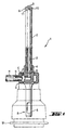
- Fig. 1 shows an overall provided with the reference numeral 1, according to the invention trained drilling tool, which is indicated in a tool holder R of a Drill M, for example, a hammer drill, is shown used.
- the Drilling tool 1 has a tubular shaft 2 with a through channel 3.
- the tubular shaft 2 is connected at one end to a connecting part 4, welded or soldered, for example, to the insertion end 5 for connection has the tool holder R of the drilling device M.
- the through channel 3 stands with a bore 6 in the connecting part 4 in connection, which in an opening 7 on the circumference of the Connection part 4 opens.
- Drill M In the axial extension of the tool holder R is on Drill M provided a rotationally fixed coupling part C, which with an annular space S is equipped with the opening 7 of the bore 6 in the connecting part 4 in Connection is established.
- the annular space S opens into a connecting piece N, to the Suction hose H is connected.
- the drilling tool 1 is equipped with a drilling head 8 which has cutting edges 9 and consists entirely of a cutting material, for example a hard metal.
- the Drilling head 8 is butt joined with the free front end of the tubular shaft 2 permanently connected, for example by welding or soldering.
- the through channel In the area of Drill head 8 is the through channel with two suction openings 11 in connection are formed by the mouth of two head channels and in the joint area of the drill head 8 are arranged with the shaft 2.
- Fig. 1 shows only one of the suction openings 11, which are formed by recesses in the side surfaces 10 of the drill head 8 are.
- the second suction opening is on the side facing away from the viewer Drilling tool 1 arranged.
- Fig. 2 shows an axial section of the front portion of the shaft 2 of the inventive Drilling tool 1 in a position rotated by 90 ° to FIG. 1.
- the one from the Mouths of the two head channels 12 suction openings 11 are on the opposite flat sides of the drill head 8 arranged and opposite the Cutting 9 of the drill head 8 axially reset.
- the head channels 12 run with respect to the axis A of the shaft 2 or with respect to the axial through-channel 3 inclined. This ensures that their mouth openings to the side surfaces 10 of the drill head 8 or to the jacket of the shaft 2 are oriented.
- the angle of inclination is denoted by a and is between about 10 ° and 70 °.
- the cross-sectional area of the head channels 12 is smaller than that Cross-sectional area of the axial through channel 3. It is preferably between approximately 30% and 70% of the cross-sectional area of the through-channel 3. A large part of the Mouth surface of the head channels 12 is in the region of the circumference of the shaft 2 or Drill head 8 arranged.
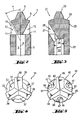
- FIG. 3 shows a second embodiment of the drilling tool according to the invention, the whole is provided with the reference numeral 21.
- the cutting edge 29 having drill head 28 on its side facing away from the cutting edges Side a pin-like, axial extension 24 which in the front portion of the Shaft 22 is embedded in the through channel 23.
- the through channel 23 has at least in the front section of the shaft 22 a deviating from the circular shape Cross-section which, for example, as indicated, is hexagonal.
- the outer contour of the axial extension 24 of the drill head 28 is the cross section of the Through channel 23 aligned.
- the drill head 28 is in addition to the Connection, for example by soldering or welding, to the free front end of the shaft 22 rotatably held in the through channel 23.
- FIG. 3 only one head channel 26 is provided, the mouth of which Suction opening 27 forms.
- the head channel 26 is in the joining area of the drill head 28 and the Shaft 22 arranged and through material cutouts in the side surface 25 of the Drill head 28 and formed at the free front end of the shaft 22.
- the suction opening is axially reset compared to the cutting edges 29.
- the head channel 26 runs opposite the axial through channel 23 is inclined such that the suction opening in the direction of Side surface 25 of the drill head 28 is oriented.
- Fig. 4 shows a plan view of the free front end of the equipped with a drill head tubular shaft of a further embodiment of the inventive Drilling tool, which is generally designated 31.
- the tubular shaft 32 has an approximately polygonal peripheral contour deviating from the circular shape.
- the Cross section of the passage 33 largely corresponds to the circumferential contour of the Shank 32.
- the drill head 38 butt-fitted with the free front end of the shaft 32 has three cutting edges 39 which are at an angular distance of approximately 120 ° from one another are arranged.
- the course of the cutting edges 39 is such that they form the jacket of the Shaft 32 inclined at an angle of approximately 90 ° ⁇ 10 °.
- the number of Suction openings 37 corresponds to the number of cutting edges 39 Suction openings 37 arranged such that when the drilling tool 31 is rotating, the Angular distance between a leading cutting edge 39 and the immediate lagging suction opening is less than 90 °.
- FIG. 5 shows a variant of a drilling head 48 having three cutting edges 49 equipped drilling tool 41.
- the tubular shaft 42 of the drilling tool has a circumferential contour deviating from the circular shape and a through channel 43, whose cross section is essentially polygonal.
- the three cutting edges are 49 arranged at an angular distance of about 120 ° to each other.
- Each of the three cutting edges 49 is assigned a suction opening 47.
- the drill head 48 has the cutting edges 49 on it facing away from a widened head base 50.
- the head base 50 are Recesses for the head channels 46 are provided in the head base 50.
- the head base 50 has side faces 51, whose projection largely corresponds to the circumferential contour of the shaft 42 coincides. In this way, the size of the joining surface is permanent Connection of the drill head 48 to the free front end of the tubular shaft 42 optimized.
- the drilling tool according to the invention is used as a suction drill was described. It is understood that the drilling tool described also in reverse operation can be used. For example, the through channel with its mouths also for flushing a borehole with air or one Flushing liquid can be used.
Landscapes
- Engineering & Computer Science (AREA)
- Mechanical Engineering (AREA)
- Processing Of Stones Or Stones Resemblance Materials (AREA)
- Earth Drilling (AREA)
- Drilling Tools (AREA)
Description
- Fig. 1
- ein in eine Werkzeugaufnahme eines Hammerbohrgerätes eingesetztes erfindungsgemässes Bohrwerkzeug;
- Fig. 2
- den vorderen Abschnitt des Bohrwerkzeugs aus Fig. 1 im Axialschnitt;
- Fig. 3
- eine Variante des Bohrwerkzeugs in einem zu Fig. 2 analogen Axialschnitt;
- Fig. 4
- eine Draufsicht auf den Bohrkopf eines dritten Ausführungsbeispiels des erfindungsgemässen Bohrwerkzeugs; und
- Fig. 5
- eine Draufsicht auf ein weiteres Ausführungsbeispiel des erfindungsgemässen Bohrwerkzeugs mit einem gegenüber Fig. 4 modifizierten Bohrkopf.
Claims (10)
- Bohrwerkzeug zur Erstellung von Bohrlöchem in Gestein, Beton, Mauerwerk und dergleichen, mit einem rohrförmigen Schaft (2; 22; 32; 42), der einen in Absaugöffnungen (7, 11; 27; 37; 47) mündenden, axial verlaufenden Durchgangskanal (3; 23; 33; 43) besitzt, an seinem einen Längsende mit einem Einsteckende (5) für den Anschluss an ein Bohrgerät (M) ausgestattet ist und am gegenüberliegenden freien Vorderende einen Schneiden (9; 29; 39; 49) aufweisenden Bohrkopf (8; 28; 38; 48) trägt, der zur Gänze aus Schneidwerkstoff, vorzugsweise aus einem Hartmetall, besteht, wobei wenigstens eine Absaugöffnung (11; 27; 37; 47) von der Mündung eines Kopfkanals (12; 26; 36; 46) gebildet ist, der zumindest teilweise vom Material des Bohrkopfs (8; 28; 38; 48) berandet ist und dessen Mündungsfläche wenigstens zu einem Teil im Umfangsbereich des Schafts (2; 22; 32; 42) und/oder des Bohrkopfs (8; 28; 38; 48) angeordnet ist, dadurch gekennzeichnet, dass der Bohrkopf (8; 28; 38; 48) mit dem freien Vorderende des rohrförmigen Schafts (2; 22; 32; 42) im wesentlichen stumpf gefügt und vorzugsweise durch Schweissen oder Löten verbunden ist.
- Bohrwerkzeug nach Anspruch 1, dadurch gekennzeichnet, dass mehr als zwei Drittel der Mündungsfläche des Kopfkanals (12; 26; 36; 46) im Umfangsbereich des Schafts (2; 22; 32; 42) und/oder des Bohrkopfs (8; 28; 38; 48) angeordnet sind.
- Bohrwerkzeug nach Anspruch 1 oder 2, dadurch gekennzeichnet, dass der Kopfkanal (12; 26) in Richtung des Mantels des Schafts (2; 22) bzw. zur axialen Seitenfläche (10; 25) des Bohrkopfs (8; 28) orientiert ist und mit der Längsachse (A) des rohrförmigen Schafts (2; 22) einen Winkel (α) einschliesst, der kleiner ist als 90° und vorzugsweise zwischen 10° und 70° beträgt.
- Bohrwerkzeug nach einem der vorangehenden Ansprüche, dadurch gekennzeichnet, dass die Querschnittsfläche der Mündung des Kopfkanals (12; 26; 36; 46) kleiner ist als die Querschnittsfläche des Durchgangskanals (3; 23; 33; 43) und vorzugsweise zwischen 30% und 70% der Querschnittsfläche des Durchgangskanals beträgt.
- Bohrwerkzeug nach einem der vorangehenden Ansprüche, dadurch gekennzeichnet, dass der Kopfkanal und/oder der Durchgangskanal einen von der Kreisform abweichenden Querschnitt aufweisen.
- Bohrwerkzeug nach einem der vorangehenden Ansprüche, dadurch gekennzeichnet, dass der Schaft (22; 32; 42) eine von der Kreisform abweichende Umfangskontur aufweist.
- Bohrwerkzeug nach einem der vorangehenden Ansprüche, dadurch gekennzeichnet, dass der Durchgangskanal (23) wenigstens im Vorderabschnitt des Schafts (22) einen polygonalen Querschnitt aufweist und der Bohrkopf (28) an seiner den Schneiden (29) gegenüberliegenden Seite eine axiale Verlängerung (24) besitzt, deren Umfangskontur dem Querschnitt des Durchgangskanals (23) wenigstens bereichsweise entspricht, wobei bei montiertem Bohrkopf (28) die axiale Verlängerung (24) drehfest im Durchgangskanal (23) gehalten ist.
- Bohrwerkzeug nach einem der vorangehenden Ansprüche, dadurch gekennzeichnet, dass die Anzahl der Absaugöffnungen (37; 47) der Anzahl Schneiden (39; 49) am Bohrkopf (38; 48) entspricht und zu der in Drehrichtung nacheilenden Schneide jeweils einen Winkelabstand aufweisen, der kleiner ist als 90°.
- Bohrwerkzeug nach einem der vorangehenden Ansprüche, dadurch gekennzeichnet, dass der Bohrkopf (38; 48) drei Schneiden (39; 49) aufweist, die zueinander in einem Winkelabstand zwischen etwa 90° und etwa 180°, vorzugsweise etwa 120°, angeordnet sind.
- Bohrwerkzeug nach Anspruch 9, dadurch gekennzeichnet, dass der Schaft (42) wenigstens im vorderen Abschnitt eine polygonartige Aussenkontur aufweist und der Bohrkopf (48) derart ausgebildet ist, dass in Draufsicht eine die Schneiden (49) unterstützende, verbreiterte Kopfbasis (50) Seitenflächen (51) aufweist, die mit den Mantelflächen des Schafts (42) im wesentlichen zusammenfallen, wobei die Schneiden (49) mit den Seitenflächen (51) der Kopfbasis (50) einen Winkel von etwa 90° ± 10° einschliessen.
Applications Claiming Priority (2)
| Application Number | Priority Date | Filing Date | Title |
|---|---|---|---|
| DE19810192 | 1998-03-10 | ||
| DE19810192A DE19810192A1 (de) | 1998-03-10 | 1998-03-10 | Bohrwerkzeug |
Publications (3)
| Publication Number | Publication Date |
|---|---|
| EP0941794A2 EP0941794A2 (de) | 1999-09-15 |
| EP0941794A3 EP0941794A3 (de) | 2002-09-11 |
| EP0941794B1 true EP0941794B1 (de) | 2004-11-03 |
Family
ID=7860304
Family Applications (1)
| Application Number | Title | Priority Date | Filing Date |
|---|---|---|---|
| EP99810126A Expired - Lifetime EP0941794B1 (de) | 1998-03-10 | 1999-02-12 | Bohrwerkzeug |
Country Status (6)
| Country | Link |
|---|---|
| US (1) | US6065908A (de) |
| EP (1) | EP0941794B1 (de) |
| JP (1) | JP4421691B2 (de) |
| CN (1) | CN100364741C (de) |
| DE (2) | DE19810192A1 (de) |
| DK (1) | DK0941794T3 (de) |
Families Citing this family (34)
| Publication number | Priority date | Publication date | Assignee | Title |
|---|---|---|---|---|
| DE10000013A1 (de) * | 2000-01-03 | 2001-07-12 | Hilti Ag | Saugbohrer |
| DE10000012A1 (de) * | 2000-01-03 | 2001-07-12 | Hilti Ag | Saugbohreranschluss |
| DE10000015A1 (de) * | 2000-01-03 | 2001-07-12 | Hilti Ag | Saugwerkzeug |
| US6595305B1 (en) * | 2000-02-15 | 2003-07-22 | Kennametal Inc. | Drill bit, hard member, and bit body |
| US6860344B2 (en) | 2001-06-25 | 2005-03-01 | Kennametal Inc. | Monolithic roof cutting bit insert |
| US20030082020A1 (en) * | 2001-11-01 | 2003-05-01 | Fan-Hsien Lin | Welded micro-drill |
| SE0301456D0 (sv) * | 2003-05-20 | 2003-05-20 | Sandvik Ab | Ett eggbärande borrkropp, och ett förfarande för tillverkning av samt ett borrverktyg innefattande en dylik borrkropp |
| SE526676C2 (sv) * | 2003-05-20 | 2005-10-25 | Sandvik Intellectual Property | Eggbärande borrkropp för långhålsborrning med eggar förfärdigade i ett stycke med borrkroppen |
| SE526392C2 (sv) * | 2003-08-28 | 2005-09-06 | Seco Tools Ab | Verktygsarrangemang och verktyg för spånavverkning där verktyget har en kanal av icke-cirkulärt tvärsnitt |
| EP2032321A1 (de) * | 2006-05-22 | 2009-03-11 | Societe de Technologie Michelin | Vorrichtung und vefahren zum bohren von produkten aus kautschuk |
| US8083445B2 (en) * | 2008-05-12 | 2011-12-27 | Mori Seiki Co., Ltd. | Holder main body |
| JP5359066B2 (ja) * | 2008-07-01 | 2013-12-04 | 株式会社タンガロイ | 穴あけ工具 |
| JP5271450B2 (ja) * | 2010-05-21 | 2013-08-21 | 株式会社ミヤナガ | ドリルビット |
| US20120063856A1 (en) * | 2010-09-10 | 2012-03-15 | Makita Corporation | Dust collecting device |
| GB201015541D0 (en) * | 2010-09-17 | 2010-10-27 | Element Six Ltd | Twist drill assembly |
| CN102251518B (zh) * | 2011-05-06 | 2013-04-03 | 洪子云 | 旋泵成孔桩机 |
| DE102011087360A1 (de) * | 2011-11-29 | 2013-05-29 | Hilti Aktiengesellschaft | Absaugvorrichtung |
| CN102728872A (zh) * | 2012-06-05 | 2012-10-17 | 江苏天工工具有限公司 | 一种带抽吸装置的斜面钻头 |
| DE102012222360A1 (de) * | 2012-12-05 | 2014-06-18 | Sauer Ultrasonic Gmbh | Werkzeug, Bearbeitungsverfahren |
| CN104552616A (zh) * | 2013-10-14 | 2015-04-29 | 李斯建 | 一种吸屑式钻头 |
| EP2946860A1 (de) * | 2014-05-20 | 2015-11-25 | HILTI Aktiengesellschaft | Absaugvorrichtung |
| US10335980B2 (en) | 2015-02-13 | 2019-07-02 | Kabushiki Kaisha Miyanaga | Dust suction drill and dust suction unit |
| CN105215435A (zh) * | 2015-10-15 | 2016-01-06 | 桐城市丽琼金属制品有限公司 | 一种具备冷却系统的钻头 |
| EP3181302A1 (de) | 2015-12-14 | 2017-06-21 | HILTI Aktiengesellschaft | Handwerkzeugmaschine |
| US20180001395A1 (en) * | 2016-06-30 | 2018-01-04 | Shehkai Precision Co., Ltd. | Dust vacuuming drill device with an internal dust passageway and method for producing the same |
| US20180001396A1 (en) * | 2016-06-30 | 2018-01-04 | Shehkai Precision Co., Ltd. | Dust vacuuming drill device with an internal dust passageway and method for producing the same |
| DE102016125032A1 (de) | 2016-12-20 | 2018-06-21 | Dreps Gmbh | Absaugbohrwerkzeug sowie Verfahren zur Herstellung eines Absaugbohrwerkzeugs |
| EP3421163A1 (de) * | 2017-06-27 | 2019-01-02 | HILTI Aktiengesellschaft | Bohrer für die meisselnde bearbeitung von gestein |
| EP3421162A1 (de) | 2017-06-27 | 2019-01-02 | HILTI Aktiengesellschaft | Bohrer für die meisselnde bearbeitung von gestein |
| DE102017219452A1 (de) * | 2017-10-30 | 2019-05-02 | Robert Bosch Gmbh | Bohrwerkzeug |
| DE102017219444A1 (de) * | 2017-10-30 | 2019-05-02 | Robert Bosch Gmbh | Bohrwerkzeug |
| DE102017219439A1 (de) * | 2017-10-30 | 2019-05-02 | Robert Bosch Gmbh | Bohrwerkzeug |
| DE102017219447A1 (de) | 2017-10-30 | 2019-05-02 | Robert Bosch Gmbh | Absaugadapter |
| CN115066318B (zh) | 2020-02-13 | 2024-05-28 | 米沃奇电动工具公司 | 具有双金属端头的工具刀头 |
Family Cites Families (14)
| Publication number | Priority date | Publication date | Assignee | Title |
|---|---|---|---|---|
| US2802642A (en) * | 1955-05-03 | 1957-08-13 | Westinghouse Air Brake Co | Rock drill bit |
| US3163246A (en) * | 1963-04-18 | 1964-12-29 | Westinghouse Air Brake Co | Rock drill bit |
| US3767315A (en) * | 1971-12-30 | 1973-10-23 | D Burks | Fluid assisted drill construction |
| DE2807197A1 (de) * | 1978-02-20 | 1979-08-30 | Heller Verwaltungsges | Bohrkopf eines drehschlagbohrers |
| US4189013A (en) * | 1978-05-18 | 1980-02-19 | Gte Sylvania Incorporated | Roof drill bit |
| US4190128A (en) * | 1978-12-21 | 1980-02-26 | Fansteel Inc. | Roof drill bit with hexagonal body portion |
| DE7908923U1 (de) * | 1979-03-29 | 1980-03-13 | Guergen, Karlheinz, 2110 Buchholz | Vorrichtung zum gesteinsbohren mit einem gesteinsbohrer |
| US4515230A (en) * | 1982-10-25 | 1985-05-07 | Fansteel Inc. | Roof drill bit |
| SE456808B (sv) * | 1987-02-19 | 1988-11-07 | Tonie Schagerstroem | Borr foer sten och betong |
| DE3835025A1 (de) * | 1988-10-14 | 1990-04-19 | Fischer Artur Werke Gmbh | Bohrvorrichtung zur herstellung von bohrloechern mit hinterschneidung |
| US5297643A (en) * | 1990-12-19 | 1994-03-29 | Kennametal Inc. | Cold headed center vacuum drill bit |
| DE4132228A1 (de) * | 1991-09-27 | 1993-04-01 | Fischer Artur Werke Gmbh | Bohrvorrichtung zur herstellung von bohrloechern mit hinterschneidung |
| US5458210A (en) * | 1993-10-15 | 1995-10-17 | The Sollami Company | Drill bits and blades therefor |
| DE4339245A1 (de) * | 1993-11-18 | 1995-05-24 | Hilti Ag | Spiralbohrer |
-
1998
- 1998-03-10 DE DE19810192A patent/DE19810192A1/de not_active Withdrawn
-
1999
- 1999-02-12 EP EP99810126A patent/EP0941794B1/de not_active Expired - Lifetime
- 1999-02-12 DE DE59910960T patent/DE59910960D1/de not_active Expired - Lifetime
- 1999-02-12 DK DK99810126T patent/DK0941794T3/da active
- 1999-03-08 JP JP05984799A patent/JP4421691B2/ja not_active Expired - Lifetime
- 1999-03-08 US US09/264,351 patent/US6065908A/en not_active Expired - Lifetime
- 1999-03-09 CN CNB991039335A patent/CN100364741C/zh not_active Expired - Lifetime
Also Published As
| Publication number | Publication date |
|---|---|
| JPH11291235A (ja) | 1999-10-26 |
| US6065908A (en) | 2000-05-23 |
| DE19810192A1 (de) | 1999-09-16 |
| JP4421691B2 (ja) | 2010-02-24 |
| DK0941794T3 (da) | 2005-03-14 |
| EP0941794A2 (de) | 1999-09-15 |
| CN1232740A (zh) | 1999-10-27 |
| EP0941794A3 (de) | 2002-09-11 |
| CN100364741C (zh) | 2008-01-30 |
| DE59910960D1 (de) | 2004-12-09 |
Similar Documents
| Publication | Publication Date | Title |
|---|---|---|
| EP0941794B1 (de) | Bohrwerkzeug | |
| DE102016118658B4 (de) | Invers verjüngte schäfte und komplementäre fussblockbohrungen für meisselanordnungen | |
| DE60308291T2 (de) | Tiefbohrwerkzeug | |
| DE19780282B3 (de) | Freitragend ausgebildeter Erweiterungsbohrer | |
| EP0884448B1 (de) | Gesteinsbohrmeissel mit wendelförmigen Abfuhrnuten | |
| DE19810193A1 (de) | Bohrwerkzeug | |
| DE2945766C2 (de) | Bohrkrone und Bohrwerkzeug mit einer solchen Bohrkrone | |
| DE60016782T2 (de) | Selbstbohrender ankerbolzen | |
| DE3406441A1 (de) | Schneidorgan und bohrmeissel | |
| DE19545648A1 (de) | Drehschlag-Wendelbohrer | |
| DE112010000716T5 (de) | Dachbohrmeissel, dachbohrmeisselkörper undharter schneideinsatz für den dachbohrmeissel | |
| EP0878261A1 (de) | Bohrwerkzeug | |
| DE3407427A1 (de) | Bohrkrone | |
| EP1780375B1 (de) | Fräszahn für ein Bodenbearbeitungsgerät | |
| EP1564365A2 (de) | Bohrkrone | |
| EP1083294B1 (de) | Bohrwerkzeug | |
| DE102004022747A1 (de) | Spanwerkzeug mit geometrisch bestimmten Schneiden für Drehantrieb | |
| EP0563561A1 (de) | Bohrkrone zum Überlagerungsbohren | |
| WO2018050267A1 (de) | Bohrkopf und bohrwerkzeug | |
| DE10044369A1 (de) | Schnellwechselhaltersystem für Werkzeuge auf Walzen | |
| EP1083295B1 (de) | Bohrwerkzeug | |
| EP1604793A1 (de) | Bohrer | |
| DE2756140A1 (de) | Gesteinsbohrer fuer bohrloecher kleineren durchmessers | |
| DE3143462A1 (de) | Bohrwerkzeug | |
| EP0778390B1 (de) | Drehschlag-Wendelbohrer |
Legal Events
| Date | Code | Title | Description |
|---|---|---|---|
| PUAI | Public reference made under article 153(3) epc to a published international application that has entered the european phase |
Free format text: ORIGINAL CODE: 0009012 |
|
| AK | Designated contracting states |
Kind code of ref document: A2 Designated state(s): AT BE CH CY DE DK ES FI FR GB GR IE IT LI LU MC NL PT SE |
|
| AX | Request for extension of the european patent |
Free format text: AL;LT;LV;MK;RO;SI |
|
| PUAL | Search report despatched |
Free format text: ORIGINAL CODE: 0009013 |
|
| AK | Designated contracting states |
Kind code of ref document: A3 Designated state(s): AT BE CH CY DE DK ES FI FR GB GR IE IT LI LU MC NL PT SE |
|
| AX | Request for extension of the european patent |
Free format text: AL;LT;LV;MK;RO;SI |
|
| 17P | Request for examination filed |
Effective date: 20030311 |
|
| AKX | Designation fees paid |
Designated state(s): CH DE DK FR GB LI SE |
|
| 17Q | First examination report despatched |
Effective date: 20031107 |
|
| GRAP | Despatch of communication of intention to grant a patent |
Free format text: ORIGINAL CODE: EPIDOSNIGR1 |
|
| GRAS | Grant fee paid |
Free format text: ORIGINAL CODE: EPIDOSNIGR3 |
|
| GRAA | (expected) grant |
Free format text: ORIGINAL CODE: 0009210 |
|
| AK | Designated contracting states |
Kind code of ref document: B1 Designated state(s): CH DE DK FR GB LI SE |
|
| REG | Reference to a national code |
Ref country code: GB Ref legal event code: FG4D Free format text: NOT ENGLISH |
|
| REG | Reference to a national code |
Ref country code: SE Ref legal event code: TRGR |
|
| REG | Reference to a national code |
Ref country code: CH Ref legal event code: EP |
|
| REF | Corresponds to: |
Ref document number: 59910960 Country of ref document: DE Date of ref document: 20041209 Kind code of ref document: P |
|
| REG | Reference to a national code |
Ref country code: IE Ref legal event code: FG4D Free format text: GERMAN |
|
| GBT | Gb: translation of ep patent filed (gb section 77(6)(a)/1977) |
Effective date: 20050110 |
|
| REG | Reference to a national code |
Ref country code: DK Ref legal event code: T3 |
|
| REG | Reference to a national code |
Ref country code: IE Ref legal event code: FD4D |
|
| PLBE | No opposition filed within time limit |
Free format text: ORIGINAL CODE: 0009261 |
|
| STAA | Information on the status of an ep patent application or granted ep patent |
Free format text: STATUS: NO OPPOSITION FILED WITHIN TIME LIMIT |
|
| ET | Fr: translation filed | ||
| 26N | No opposition filed |
Effective date: 20050804 |
|
| PGFP | Annual fee paid to national office [announced via postgrant information from national office to epo] |
Ref country code: DK Payment date: 20090213 Year of fee payment: 11 |
|
| PGFP | Annual fee paid to national office [announced via postgrant information from national office to epo] |
Ref country code: CH Payment date: 20090213 Year of fee payment: 11 |
|
| PGFP | Annual fee paid to national office [announced via postgrant information from national office to epo] |
Ref country code: SE Payment date: 20090206 Year of fee payment: 11 |
|
| REG | Reference to a national code |
Ref country code: CH Ref legal event code: PL |
|
| REG | Reference to a national code |
Ref country code: DK Ref legal event code: EBP |
|
| EUG | Se: european patent has lapsed | ||
| PG25 | Lapsed in a contracting state [announced via postgrant information from national office to epo] |
Ref country code: LI Free format text: LAPSE BECAUSE OF NON-PAYMENT OF DUE FEES Effective date: 20100228 Ref country code: CH Free format text: LAPSE BECAUSE OF NON-PAYMENT OF DUE FEES Effective date: 20100228 |
|
| PG25 | Lapsed in a contracting state [announced via postgrant information from national office to epo] |
Ref country code: DK Free format text: LAPSE BECAUSE OF NON-PAYMENT OF DUE FEES Effective date: 20100228 |
|
| PGFP | Annual fee paid to national office [announced via postgrant information from national office to epo] |
Ref country code: GB Payment date: 20120208 Year of fee payment: 14 |
|
| PG25 | Lapsed in a contracting state [announced via postgrant information from national office to epo] |
Ref country code: SE Free format text: LAPSE BECAUSE OF NON-PAYMENT OF DUE FEES Effective date: 20100213 |
|
| GBPC | Gb: european patent ceased through non-payment of renewal fee |
Effective date: 20130212 |
|
| PG25 | Lapsed in a contracting state [announced via postgrant information from national office to epo] |
Ref country code: GB Free format text: LAPSE BECAUSE OF NON-PAYMENT OF DUE FEES Effective date: 20130212 |
|
| REG | Reference to a national code |
Ref country code: FR Ref legal event code: PLFP Year of fee payment: 18 |
|
| REG | Reference to a national code |
Ref country code: FR Ref legal event code: PLFP Year of fee payment: 19 |
|
| REG | Reference to a national code |
Ref country code: FR Ref legal event code: PLFP Year of fee payment: 20 |
|
| PGFP | Annual fee paid to national office [announced via postgrant information from national office to epo] |
Ref country code: DE Payment date: 20180219 Year of fee payment: 20 |
|
| PGFP | Annual fee paid to national office [announced via postgrant information from national office to epo] |
Ref country code: FR Payment date: 20180222 Year of fee payment: 20 |
|
| REG | Reference to a national code |
Ref country code: DE Ref legal event code: R071 Ref document number: 59910960 Country of ref document: DE |