BACKGROUND OF THE INVENTION
Field of the Invention
The present invention relates to a milling machine which
produces crushed stones by crushing an arbitrary ore through use
of predetermined crushing members stored in a shell main unit, to
a method of crushing an ore through use of the milling machine, and
to a method of manufacturing the milling machine.
Description of the Related Art
In principle, a shell main unit of a conventional milling
machine is formed into the shape of a hollow cylinder. A milling
machine has a shell main unit of one of the below-described types
intended for improving the efficiency of crushing ore by dropping
and rotating grinding members provided in the shell main unit. For
example, when the shell main unit is viewed from the side, an
ore-feeder portion of the shell main unit is formed into the shape
of a hollow cylinder, whereas an outlet portion of the shell main
unit is formed into the shape of a hollow truncated cone tapered
toward the direction of discharge. Another type of shell main unit
has a reverse structure; namely, the ore-feeder portion of the shell
main unit is formed into the shape of hollow truncated cone, whilst
the outlet portion of the same is formed into the shape of a hollow
cylinder. The grinding member is formed into the shape of a sphere
or a deformed rectangular polyhedron.
The efficiency of crushing ore has been known to be improved
by uniform and balanced distribution of grinding members within the
shell main unit. The reason for this is that uniform distribution
of grinding members results in crushing action uniformly acting on
ore, thereby enabling excessive crushing of ore and energy loss.
Since the amount of crushing energy to be dissipated is proportional
to the size of a substance to be crushed, crushing action is uniformly
exerted on ore by uniform distribution of crushing members, thereby
improving the quality of crushed stones.
However, in the milling machine which has conventionally been
utilized, the shape of the milling machine makes attainment of
uniform distribution of crushing members within the shell main unit
difficult. For this reason, the conventional milling machine
experiences difficulty in greatly improving the efficiency of
crushing ore and is apt to cause excessive crushing of ore.
SUMMARY OF THE INVENTION
Accordingly, the object of the present invention is to provide
a milling machine which enables an improvement in an efficiency of
crushing ore through uniform distribution of grinding members within
a shell main unit and an improvement in the quality of crushed stones
by prevention of excessive crushing of ore.
More specifically, according to a first aspect of the present
invention, there is provided a milling machine for crushing ore into
crushed stones comprising:
In this milling machine, the shell main unit assumes the
foregoing shape, grinding members can be uniformly distributed
within the entire shell main unit. Accordingly, the efficiency of
crushing the ore can be improved to a much greater extent, thereby
enabling a reduction in energy loss.
Preferably, the cone angle of the second cylindrical section
is greater than the cone angle of the first cylindrical section.
Since the first cylindrical section is tapered, the grinding members
can be prevented from accumulating in a specific location of the
first cylindrical section. Since the cone angle of the second
cylindrical section is greater than that of the first cylindrical
section, crushed stone and the grinding members are conveyed to the
crushed-stone-outlet side through utilization of a difference in
peripheral speed arising from rotation of the shell main unit,
thereby enabling effective output of the ore to the outside.
Accordingly, ore to be conveyed is prevented from accumulating in
a connection section between the first cylindrical section and the
second cylindrical section, thereby enabling uniform arrangement
of the grinding members.
Preferably, the cone angle of the first cylindrical section
is very small, and the cone angle of the second cylindrical section
is significantly larger than that of the first cylindrical section.
As a result, the ore and the milling members can be distributed more
uniformly within the entire shell main unit. In other words, since
the first cylindrical section assumes a very small cone angle, the
grinding members can be uniformly distributed without accumulating
in a specific location. Since the cone angle of the second
cylindrical section is made so as to become significantly larger
than that of the first cylindrical section, the crushed ore and the
grinding members are conveyed to the outlet side through utilization
of a difference in peripheral speed arising from rotation of the
shell main unit, thereby effectively outputting the ore to the
outside. Accordingly, the ore to be conveyed is prevented from
accumulating in a connection section between the first cylindrical
section and the second cylindrical section, thereby rendering the
grinding members more uniform.
The large grinding members and the large pieces of ore
concentrate in the first cylindrical section. In the second
cylindrical section, the grinding members and the pieces of ore are
uniformly arranged so as to become smaller in diameter toward the
crushed-stone-outlet side. Therefore, the first cylindrical
section provides the grinding members and the ore with the maximum
drop and peripheral speed. Since the ore is crushed by the grinding
members of large diameters, the ore is crushed with maximum physical
impact. In the second cylindrical section, the grinding members
and the pieces of ore become gradually smaller in drop and peripheral
speed toward the crushed-stone-outlet side. The ore is crushed by
the grinding members having smaller diameters, thereby preventing
excessive crushing of the ore and resulting in an improvement in
quality of crushed stones.
Preferably, assuming that the inner diameter of an ore-supply-side
portion of the first cylindrical section is taken as
S1, the inner diameter of a crushed-stone-outlet-side portion of
the first cylindrical section is taken as S2, and a distance between
the end of the ore-supply-side portion of the first cylindrical
section and the end of the ore-outlet-side portion of the same is
taken as T1, (S1-S2)/T1 assumes a value ranging from 0.01 or more
to 0.03 or less.
Preferably, the cone angle of the second cylindrical section
ranges from 30 degrees to 50 degrees.
Preferably, the longitudinal center of the shell main unit
resides in the first cylindrical section. As a result of the
cylindrical section tapered with a very small cone angle being made
longer than the cylindrical section tapered with a significantly
large cone angle, the ore and the grinding members are prevented
from accumulating in the vicinity of the exit of the shell main unit,
which would otherwise be caused by an excessive increase in the
efficiency of discharge.
Preferably, the ratio between the cone angle of the first
cylindrical section and the cone angle of the second cylindrical
section and the ratio between the axial length of the first
cylindrical section and the axial length of the second cylindrical
section are set such that the grinding members achieve a
substantially uniform distribution within the shell main unit.
Consequently, uniform distribution of the grinding members within
the shell main unit enables improvement in the efficiency of crushing
ore, as well as improvement in the quality of crushed stone.
Preferably, a liner is provided on the internal wall
surface of the first and second cylindrical sections in the shell
main unit. As a result, the efficiency of crushing ore can be
improved in association with uniform distribution of the grinding
members within the shell main unit.
Preferably, the milling machine further comprising: an ore
storage section for storing ore which is to be fed; an ore conveying
section for conveying the ore stored in the ore storage section to
the shell main unit; at least a pair of outer ring members provided
around the outer periphery of the shell main unit; and a drive
apparatus for rotating the shell main unit.
In this milling machine, the ore fed from the ore storage
section is supplied into the shell main unit by way of the ore
conveying section, and the shell main unit is rotated by the drive
apparatus by way of the outer ring members.
Preferably, a crushed-stone outlet port is provided on
the end of the crushed stone outlet side portion of the second
cylindrical section, and a partition plate is provided so as to
become spaced away from the crushed-stone outlet port by a given
gap. Consequently, uncrushed stone or the grinding members of large
diameters can be prevented from outputting from the shell main unit.
Preferably, slits are formed in an outer side of the
partition plate to such a size as to hinder passage of the grinding
members, and holes are formed in an inner side of the partition plate
to such a size as to hinder passage of gravel.
Preferably, a substantially circular opening is formed
in substantially the center of the partition plate.
Preferably, the milling machine further comprising
grinding members in the shell main unit.
According to a second aspect of the present invention, there
is provided a method of crushing ore through use of a milling machine
that comprises a hollow shell main unit made by continuously joining
together a first cylindrical section-which is provided on an ore
supply side and is tapered with a very small cone angle so as to
have a larger inner diameter toward the ore supply side-and a second
cylindrical section which is provided on a crushed stone outlet side
and is tapered with a cone angle significantly greater than that
of the first cylindrical section such that the inner diameter of
the second cylindrical section becomes smaller toward the crushed
stone outlet side, the method comprising the steps of:
Under the crushing method by use of the milling machine, the
grinding members are actively and uniformly distributed by means
of the shape of the first cylindrical section tapered with a very
small cone angle and the shape of the second cylindrical section
tapered with a significantly large cone angle, thereby enabling an
improvement in the efficiency of crushing ore with the grinding
members.
According to a third aspect of the present invention, there
is provided a method of manufacturing a milling machine having a
shell main unit, wherein the hollow shell main unit is manufactured
by continuously joining together a first cylindrical section-which
is provided on an ore supply side and is tapered with a very small
cone angle so as to have a larger inner diameter toward the ore supply
side-and a second cylindrical section-which is provided on a
crushed stone outlet side and is tapered with a cone angle
significantly greater than that of the first cylindrical section
such that the inner diameter of the second cylindrical section
becomes smaller toward the crushed stone outlet side-through
setting of a ratio of cone angle between the first cylindrical
section and the second cylindrical section and a ratio of axial
length between the first cylindrical section and the second
cylindrical section such that the grinding members are uniformly
distributed within the shell main unit.
As a result, in a case where ore is crushed by use of the milling
machine manufactured by the foregoing manufacturing method, the
efficiency of crushing ore can be improved by uniform distribution
of the grinding members within the shell main unit, thereby
preventing excessive crushing of ore and enabling improvement in
the quality of crushed stone.
Still other objects of the present invention will become
readily apparent to those skilled in the art from the following
description wherein there is shown and described a preferred
embodiment of the present invention, simply by way of illustration
of one of the modes best suited to carry out the invention. As it
will be realized, the invention is capable of other different
embodiments, and its several details are capable of modifications
in various, obvious aspects all without departing from the invention.
Accordingly, the drawings and descriptions will be regarded as
illustrative in nature and not as restrictive.
BRIEF DESCRIPTION OF THE DRAWINGS
The accompanying drawings incorporated in and forming a part
of the specification, illustrate several aspects of the present
invention, and together with the description serve to explain the
principles of the invention. In the drawings:
Reference will now be made in detail to the present preferred
embodiment of the invention, an example of which is illustrated in
the accompanying drawings.
DESCRIPTION OF THE PREFERRED EMBODIMENT
A preferred embodiment of the present invention will now be
described by reference to the accompanying drawings.
As shown in Fig. 1, a milling machine A1 according to a first
embodiment comprises a hopper B10 serving as an ore storage section;
a shell main unit C1; outer ring members D1; a partition plate E1;
a classifier F1; and a drive unit G1.
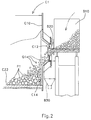
As shown in FIG. 2, the hopper B10 assumes the shape of a vessel,
and a chute 20 is formed at the lower end of the side surface of
the hopper B10. The chute B20 has an outlet port for ore. When ore
Q1 is fed into the hopper B10 from the outside, the ore Q1 is fed
into an ore supply section C10 of the shell body C1, which will be
described later, by way of the chute 20 in metered amounts. The
chute B20 acts as an ore delivery section.
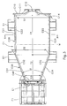
As shown in Fig. 3, the shell main unit C1 comprises the ore
supply section C10, a first cylindrical section C20, and a second
cylindrical section C30.
The ore supply section C10 is substantially formed into the
shape of a disk, and an ore inlet port C12 is formed in the center
of the ore supply section C10 for the purpose of feeding of the ore
Q1. The portion of the ore supply section C10 where the ore inlet
port C12 is formed protrudes to the outside in a tapered manner.
The ore supply section C10 serves as a side wall of an ore-supply
side portion of the shell main unit C1. The chute B20 is fitted
to the ore inlet port C12, and the ore Q1 is fed into the shell main
unit C1.
Specifically, the ore supply section C10 has an outer wall
section C11 and a liner C14, and the outer wall section C11
substantially assumes the shape of a disk. An opening where the
ore inlet port C12 will be formed is formed in the center of the
outer wall section C11, and the area of the ore supply section C10
where the opening is formed protrudes toward the outside in a tapered
manner.
A collector section B30 is disposed below the ore feed portion
C12 for the purpose of collecting overflowing ore or water.
The liner C14 is formed from metal or rubber over the internal
wall surface of the shell main unit , i.e., the inner surface of
the outer wall section C11. The liner C14 is uniformly formed so
as to extend from the inner periphery of the outer wall section C11
up to the internal wall surface of the ore inlet port C12.
As shown in Figs. 3 and 4, the first cylindrical section C20
substantially assumes a cylindrical shape and is positioned in the
vicinity of the ore supply section in the longitudinal direction
of the shell main unit C1. The first cylindrical section C20 is
actually formed into the shape of a truncated cone which is tapered
with a very small cone angle (not shown) such that the inner diameter
of the first cylindrical section C20 becomes slightly greater toward
the ore supply section. More specifically, the first cylindrical
section C20 is formed such that an inner diameter S2 of the
outlet-side portion thereof becomes smaller than an inner diameter
S1 of the supply-side portion of the same. Here, the cone angle
of the tapered first cylindrical section C20 corresponds to the angle
which the outer surface of the first cylindrical section C20 forms
with a plane surface passing through the rotation axis of the first
cylindrical section C20.
In short, the first cylindrical section C20 comprises an outer
wall section C21 and a liner C22, and the outer wall section C21
substantially assumes the shape of a cylinder and is formed into
a truncated cone which is tapered by a very small cone angle such
that the inner diameter thereof becomes greater toward the supply
side portion of the outer wall section C21.
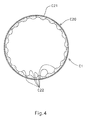
As shown in Fig. 4, the liner C14 is provided on an internal
wall surface serving as the interior of the shell main unit, i.e.,
the inner surface of the outer wall section C21. More specifically,
a plurality of substantially rectangular plane liners C22 formed
from metal or rubber are uniformly laid on the internal surface of
the first cylindrical section C20. As shown in Fig. 4, a one-half
or more of each liner C22 is formed into a substantially oval-shaped
protuberance, and the first cylindrical section C20 is formed so
as to assume a longitudinal dimension T1, as shown in Fig. 3.
In a case where the first cylindrical section C20 assumes an
internal diameter of about 2000mm and cone angle a is defined as
α=(S1-S2)/T1, the first cylindrical section C20 assumes a very small
cone angle of 0.01≤α≤0.03 or thereabouts, which through
experimentation has been found to be preferable.
As shown in Fig. 3, the second cylindrical section C30 is
substantially formed into the shape of truncated cone and is provided
in the vicinity of a crushed stone outlet side of the shell main
unit C1 in its longitudinal direction. The second cylindrical
section C30 is formed in such a way as to assume a smaller internal
diameter toward its outlet side and is sharply tapered with a cone
angle greater than that of the first cylindrical section C20. In
short, the second cylindrical section C30 is formed such that the
inner diameter S3 of the outlet side thereof becomes sharply smaller
than the inner diameter S2 of the supply-side portion of the same,
as will be described later.
Specifically, the second cylindrical section C30 comprises
an outer wall section C31 and a liner C32. The outer wall section
C31 is formed such that the inner diameter thereof becomes smaller
toward the outlet side and is formed into the shape of a truncated
cone whose cone angle is greater than that of the first cylindrical
section C20.
Similar to the case of the first cylindrical section C20 as
shown in Fig. 4, in the second cylindrical section C30 the liner
C32 is provided on the internal wall surface serving as the interior
of the shell main unit, i.e., the internal surface of the outer wall
section C31. More specifically, a plurality of substantially
rectangular plane liners C32 formed of metal or rubber are uniformly
laid on the internal surface of the second cylindrical section C30.
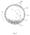
The liner C32 assumes the same cross section as that of the liner
C22, as shown in Fig.7,
As shown in Fig. 3, the second cylindrical section C30 is
formed so as to assume a longitudinal length of T2, and a
crushed-stone outlet port C40 is formed in the crushed-stone-outlet-side
portion of the second cylindrical section C30.
In a case where crushed stones assume a size of several
millimeters or thereabout, the second cylindrical section C30
assumes a sharp cone angle , shown in Fig. 3, of 30°≤≤50° or
thereabouts, which through experimentation has been found to be
preferable. The angle corresponds to the cone angle of the second
cylindrical section C30. Here, the cone angle of the tapered second
cylindrical section C30 corresponds to the angle which the outer
surface of the second cylindrical section C30 forms with a plane
surface passing through the rotation axis of the second cylindrical
section C30.
The first cylindrical section C20 and the second cylindrical
section C30 are connected together seamlessly, thereby constituting
the hollow shell main unit C1. The axial length T1 of the first
cylindrical section C20 is set as to be longer than the axial length
T2 of the second cylindrical section C30.
Given that ϒ=T2/(T1+T2), a preferred ratio between the length
T1 and the length T2 is 0.32≤ϒ≤0.39 or thereabouts, which through
experimentation has been found to be preferable.
As shown in Fig. 3, the longitudinal center W of the shell
main unit C1 resides in the first cylindrical section C20.
As shown in Figs. 1 and 3, each of the pair of outer ring members
D1 assumes the shape of a substantially circular strip and is
provided along and integrally with the outer peripheral surface of
the shell main unit C1; more particularly, one of the outer members
D1 is provided in the vicinity of the ore supply section of the shell
main unit C1 and the other is provided in the vicinity of the outlet
side of the same. The pair of outer ring members D1 is provided
on a group of tire sets G5, and each tire set G5 comprises two tires
G10. Although Fig. 1 shows only two tires sets G5 provided on the
front side of the milling machine A1, another group of tires G1 is
provided on the back side of the milling machine A1 behind the outer
ring members D1. Since the outer ring members D1 remain in pressed
contact with the group of tires G5, the outer ring members D1 are
also rotated in conjunction with the tires G5 when the group of tires
G5 is rotated by a drive unit G1.
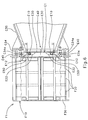
As shown in Fig. 5, the partition plate E1 is formed
substantially into the shape of a disk and is disposed so as to become
spaced from the crushed-stone outlet port C40 of the shell main unit
C1 by only a gap U, as shown in Fig. 6. Here, the partition plate
E1 in Fig. 6 is drawn in accordance with a cross-sectional view taken
along line Y-Y shown in Fig. 5.
As shown in Figs. 5 and 6, an outer diametrical portion of
the partition plate E1 is formed by joining together five fan-shaped
slit members E10 which are segmented with respect to the center of
the partition plate E1. The five slit members E10 are fixed together
through use of joint members E12 through welding. An inner
diametrical portion of the partition plate E1 is formed from a single
disk-shaped gravel-stop member E20, and joint members E22 are fixed
to the gravel-stop member E20 by welding.
As shown in Figs. 5 and 6, brackets C34 protruding from the
edge of the second cylindrical section C30 are fastened to the joint
members E12 by means of bolts E40, and the joint members E12 are
fastened to the joint members E22 by means of bolts E50.
As shown in Fig. 6, each of the brackets C34 is fastened to
the corresponding joint member E12 by way of an elongated hole C34a
formed in the bracket C34. Therefore, the position of the partition
plate E1 can be adjusted in the axial direction of the shell main
unit C1. As shown in Fig. 6, the elongated hole C34a is formed so
as to be longer in the axial direction of the shell main unit C1.
As a result, the gap U between the crushed-stone out let port C40
can be changed in accordance with the volume of ore Q1 to be fed
into the milling machine A1 as well as with the size of crushed stones
R1 to be output.
As shown in Fig. 5, a plurality of grinding member stop slits
E14 are formed in each of the slit members E10, and a plurality of
gravel-stop holes E24 are formed in the gravel-stop member E20.
Furthermore, an opening E30 of substantially circular shape is
formed in the gravel-stop member E20. Preferably, the grinding
member stop slits E14 and the gravel-stop holes E24 are formed so
as to become tapered such that the holes and slits have a greater
diameter at their outlet-side portions than at their diameter in
their shell-main-unit-side portions. Even if crushed stones or
debris enter the grinding member stop slits E14 or the gravel-stop
holes E24, they will be readily released.
As shown in Fig. 6, the classifier F1 is substantially formed
into the overall shape of a cylinder, and the outer periphery of
the classifier F1 is formed into a cylindrical member F10. The
cylindrical member F10 is fastened to the shell main unit C1 by means
of bolts and rotates simultaneous with rotation of the shell main
unit C1. A screen member F20 is provided along the outer periphery
of the cylindrical member F10 while being divided in three segments
in the axial direction thereof and permits selective passage of only
crushed stone of a certain particle size. As shown in Fig. 6, an
opening not having a screen is formed in a forward end section F30
of the cylindrical body F10. The opening allows discharge of crushed
stones which is of greater than a certain particle size and cannot
pass through the screen member F20. The classifier F1 has a
capability of classifying crushed stone which is of certain particle
size and can pass through the screen member F20 and crushed stone
which is of greater than a certain particle size and cannot pass
through the screen member F20.
The drive unit G1 comprises a motor and gears and is arranged
so as to transmit torque to the group of tires G5.
The operation and advantageous results of the present
invention will now be described.
As shown in Fig. 2, grinding members P1-which comprise a
mixture of different sized grinding members and are each formed into
the shape of a sphere-are housed in the shell main unit C1. The
ore Q1 fed from the hopper B10 is supplied in metered amounts into
the shell main unit C1 along a slope of the chute B20 by way of the
ore inlet port C12. In a case where the ore is fed with water, a
predetermined amount of water is also supplied to the shell main
unit C1 together with the ore Q1.
By force of gravity, the ore Q1 is supplied from the hopper
B10 and the chute B20 to the shell main unit C1. Therefore, the
milling machine A1 does not require an ore supply apparatus which
forcefully supplies ore into the shell main unit C1 by means of a
commonly-employed drive unit.
As shown in Fig. 3, since the crushed-stone outlet port C40
is sufficiently larger in diameter than the ore inlet port C12, the
ore Q1 is smoothly conveyed and discharged and does not accumulate
in the vicinity of the ore supply section C10. Therefore, there
is no need to squeeze the ore Q1 into the ore supply section C10.
Since the milling machine A1 does not need the foregoing forceful
ore supply apparatus, the milling machine A1 can accordingly be
formed into a simple and inexpensive structure. Alternatively, the
milling machine may be formed by use of a forceful ore supply
apparatus such as that mentioned previously. In this case, even
when a large volume of ore is fed into the milling machine A1, the
ore can be smoothly fed and discharged.
As shown in Fig. 7, when the shell main unit C1 is rotated
by the drive unit G1 by way of the tires G10 and the outer ring members
D1, the grinding members P1 are raised by action of the plurality
of liners C22. When the liner C22 is raised to such an angle in
relation to the horizontal plane thereof so as to be unable to hold
the grinding members P1, the grinding members P1 are dropped as shown
in the drawing. As a result, the ore Q1 positioned directly below
the grinding member P1 is crushed by means of the grinding members
P1.
As mentioned previously, the first cylindrical section C20
is tapered with a very small cone angle, and the second cylindrical
section C30 is tapered with a cone angle greater than that of the
first cylindrical section C20. Further, the axial center of the
shell main unit C1 resides in the first cylindrical section C20.
As shown in Fig. 8, the grinding members P1 are distributed uniformly
(in a horizontal direction) within the shell main unit C1. The
reason for this is will now be described.
The movement of the grinding members P1 is pursuant to the
basic principle of a milling machine; namely, larger grinding
members move toward an opening having a large diameter, and smaller
grinding members move toward an opening having a small diameter.
As mentioned above, the first cylindrical section C20 is tapered
with a very small cone angle such that the inner diameter of the
first cylindrical section C20 becomes greater toward the ore supply
section. Therefore, the grinding members P1 do not move toward any
direction because of variations in the diameter of the grinding
members P1. If the first cylindrical section C20 is tapered with
a large cone angle, the grinding members P1 having large diameters
concentrate in an area designated by P10 shown in Fig. 8 (i.e., the
side of the shell main unit Q1 into which the ore Q1 is fed), whereas
the grinding members P1 having smaller diameters concentrate in an
area designated by P20 shown in Fig. 8 (i.e., the center of the shell
main unit C1). Such concentration of grinding members in any
location does not occur in the present embodiment.
Conversely, if the first cylindrical section C20 is not
tapered at all, there is a reduction in the effect of discharging
the ore Q1 toward the outlet side by means of a difference in
circumferential speed. As a result, the ore Q1 accumulates in the
position designated by P10 shown in Fig. 8.
Accordingly, the first cylindrical section C20 is set so as
to be tapered with a very small cone angle, thereby enabling uniform
distribution of the grinding members P1. For this reason, the
efficiency of crushing the ore Q1 through rotation and drop of the
grinding members P1 can be improved.
The very small cone angle of the first cylindrical section
C20 is determined according to the material, size, shape, and volume
of the grinding members P1 fed into the milling machine A1, as
required.
The second cylindrical section C30 is tapered toward the
outlet side with a cone angle larger than that of the first
cylindrical section C20. With this configuration, the tapered
section having a large cone angle causes a great difference in
circumferential speed, and therefore the ore Q1 conveyed from the
first cylindrical section C20 can be sufficiently discharged to the
crushed-stone outlet port C40. Therefore, the ore Q1 and the
grinding members P1 are prevented from accumulating in the area
designated by P20 shown in Fig. 8, which would otherwise be caused
by insufficient conveyance. As a result of the second cylindrical
section C30 being tapered with a cone angle greater than that of
the first cylindrical section C20, the distribution of the grinding
members P1 can be made uniform, thereby enabling an improvement in
the efficiency of crushing the ore Q1 through rotation and drop of
the grinding mernbers P1.
The cone angle of the second cylindrical section C30 is
determined according to the material, size, shape, and volume of
the grinding members P1 fed into the milling machine A1, as required.
The axial center W of the shell main unit C1 resides in the
first cylindrical section C20, and the first cylindrical section
C20 is longer than the second cylindrical section C30. Accordingly,
the portion of the first cylindrical section C20 tapered with a very
small cone angle is longer than the portion of the second cylindrical
section C30 tapered with a large cone angle. For this reason,
neither the ore Q1 nor the grinding members P1 accumulate in the
vicinity of the crushed-stone outlet port C40. In other words, the
ore Q1 and the grinding members P1 are prevented from accumulating
in an area designated by P30 shown in Fig. 8 (i.e., in the vicinity
of the crushed-stone outlet port C40), which would otherwise be
caused by an excessive increase in the efficiency of discharge.
As mentioned above, by means of the ratio (or balance) among
the very small cone angle of the first cylindrical section C20, the
large cone angle of the second cylindrical section C30, the length
of the first cylindrical section C20, and the length of the second
cylindrical section C30, the grinding members P1 can be uniformly
distributed within the shell main unit C1. As a result, the
efficiency of crushing the ore Q1 through rotation and drop of the
grinding members P1 can be improved, thereby enabling a reduction
in energy loss.
The grinding members P1 and the pieces of ore Q1 having the
largest diameters concentrate in the first cylindrical section C20.
Further, in the tapered portion of the second cylindrical section
C30, the grinding members P1 and the pieces of ore Q1 are uniformly
arranged so as to become smaller in diameter toward the crushed-stone
outlet port C40. Therefore, the first cylindrical section C20
provides the grinding members P1 and the ore Q1 with the maximum
drop and peripheral speed. Since the ore Q1 is crushed by the
grinding members P1 of large diameters, the ore Q1 is crushed with
maximum physical impact. In the second cylindrical section C30,
the grinding members P1 and the pieces of ore Q1 become gradually
smaller in drop and peripheral speed toward the crushed-stone outlet
port C40. The ore Q1 is crushed by the grinding members P1 having
smaller diameters, thereby preventing excessive crushing of the ore
and resulting in an improvement in quality of crushed stones.
The ore Q1 is efficiently crushed into crushed stones R1 of
predetermined size by the uniformly-distributed grinding members
P1. The thus-crushed stone R1 is discharged to the classifier F1
in direction of arrow Ua shown in Fig. 9 from the gap U between the
crushed-stone outlet port C40 and the partition plate El.
In a case where a large volume of ore Q1 is fed into the milling
machine A1 and where the crushed stone R1 is discharged in large
amounts, the crushed stone R1 is discharged to the classifier F1,
as designated by arrow E14a shown in Fig. 9, even from the grinding
member stop slits E14 formed in each of the slit member E10. If
the size of the grinding member stop slits E14 is set to a
predetermined value or smaller, the grinding members P1 are
prevented from being discharged from the grinding member stop slits
E14 and are retained.
When the volume of ore Q1 fed into the milling machine A1
becomes greater than the foregoing volume, the crushed stone is
discharged to the classifier F1, as designated by arrow E24a shown
in Fig. 9, even from the gravel-stop holes 24 formed in the
gravel-stop member 20. If the size of the gravel-stop member E24
is set to or smaller than a predetermined value, the uncrushed pieces
of ore Q1 and the grinding members P1 are prevented from being
discharged from the gravel-stop holes E24 and are retained.
The opening E30 formed in the inner diametrical portion of
the gravel-stop hole E24 is used as a drain, as indicated by arrow
of E30a shown in Fig. 9, in the event of the gap U, the grinding
member stop slits E14, or the gravel-stop holes E24 becoming clogged
or in the event of an excessive amount of water being fed into the
milling machine A1. Further, the opening E30 is also used as an
observation window for observing the shell main unit C1 from the
outside. In normal operations, the opening E30 is not used for
discharging the crushed stones R1.
The gap U is in principle formed so as to be greater than the
width of the grinding member stop slit E14 or the width of the
gravel-stop slit E20. Consequently, the pieces of crushed stone
R1 larger than the gap U are prevented from being discharged from
the shell main unit C1.
The classifier F1 classifies the crushed stones R1 conveyed
from the second cylindrical section C30 into crushed stone R10 which
can pass through the screen member f20 and crushed stone R20 which
is greater in particle size than the crushed stone R10.
In the previously-described milling machine A1 according to
the present embodiment, the first cylindrical section C20 is tapered
with a very small cone angle, and the second cylindrical section
C30 is tapered with a cone angle far greater than that of the first
cylindrical section C20. With this structure, the very small cone
angle of the first cylindrical section C20 enables uniform
distribution of the grinding members P1 and the ore Q1 without
involvement of accumulation of the grinding members P1 and the ore
Q1. Further, since the second cylindrical section C30 is tapered
with a great cone angle, the ore Q1 crushed in the shell main unit
C1 and the grinding members P1 are conveyed to the outlet-port side
in the shell main unit C1 by utilization of a difference in peripheral
speed arising from rotation of the shell main unit C1, thereby
effectively discharging the ore Q1 to the outside. More
specifically, the ore Q1 that is conveyed from the first cylindrical
section C20 to the second cylindrical section C30 is prevented from
accumulating in a connection path between the first cylindrical
section C20 and the second cylindrical section C30, thereby
rendering the grinding members P1 more uniform. As a result, the
efficiency of crushing the ore Q1 through rotation and drop of the
grinding members P1 can be improved, and therefore energy loss can
be diminished.
The grinding members P1 and the pieces of ore Q1 having the
largest diameter concentrate in the first cylindrical section C20.
Further, in the tapered portion of the second cylindrical section
C30, the grinding members P1 and the pieces of ore Q1 are uniformly
arranged so as to become smaller in diameter toward the crushed-stone
outlet port C40. Therefore, the first cylindrical section C20
provides the grinding members P1 and the ore Q1 with maximum drop
and peripheral speed. Since the ore Q1 is crushed by the grinding
members P1 having large diameters, the pieces of ore Q1 are crushed
with the maximum physical impact. In the second cylindrical section
C30, the grinding members P1 and the ore Q1 become gradually smaller
in drop and peripheral speed toward the crushed-stone outlet port
C40. The ore Q1 is crushed by the grinding members P1 having smaller
diameters, thereby preventing excessive crushing of the ore and
resulting in an improvement in quality of crushed stones.
In manufacturing the milling machine A1, the milling machine
Al is set so as to attain an optimum ratio between the cone angle
of the first cylindrical section C20 and the second cylindrical
section C30 and an optimum ratio between the length of the first
cylindrical section C20 and the length of the second cylindrical
section C30, in order to uniformly distribute the grinding members
P1 within the shell main unit C1. Therefore, uniform distribution
of the grinding members P1 an be realized more actively, and the
efficiency of crushing the ore Q1 by means of the grinding members
P1 can be improved without fail.
As mentioned previously, the very small cone angle of the
first cylindrical section C20 and the large cone angle of the second
cylindrical section C30 depend on various elements such as (1) the
inner diameter of the first cylindrical section C20 and that of the
second cylindrical section C30; (2) a length ratio between the first
cylindrical section C20 and the second cylindrical section C30; (3)
the material, size, shape, and volume of the grinding members P1
to be used; (4) the material, size, shape, and volume of ore to be
crushed; (5) the performance of the liner to be used; and (6) the
rotation speed of the shell main unit C1. Therefore, the cone angles
of the cylindrical sections C20 and C30 cannot be calculated
directly.
For these reasons, according to (1) the preset inner diameters
of the first and second cylindrical sections C20 and C30; (2) the
material, size, shape, and volume of the grinding members P1 to be
used; (3) the material, size, shape, and volume of ore to be crushed;
(4) the performance of the liner to be used; and (5) the rotation
speed of the shell main unit C1, the ratio of cone angle between
the first cylindrical section C20 and the second cylindrical section
C30 is set such that the grinding members P1 are uniformly
distributed within the shell main unit C1, in the manner as mentioned
previously. Further, the length ratio between the first
cylindrical section C20 and the second cylindrical section C30 is
set such that the grinding members P1 are uniformly distributed
within the shell main unit C1. Thus, the cone angles and the lengths
of the first and second cylindrical sections C20 and C30 are selected
through balancing (or tuning), as required.
Although each of the grinding members P1 assumes the shape
of a sphere in the foregoing description, the present invention is
not limited solely to that shape. A grinding member of arbitrary
shape, size, and material, such as a deformed rectangular polyhedron
or a regular polyhedron, may also be used as the grinding member,
as required, according to the volume, shape, material, and size of
ore to be crushed and according to a desired shape, size, and volume
of crushed stone. Metal, ceramics, or rubber may preferably be used
as the material of the grinding member P1. However, the material
is not limited solely to these materials, and arbitrary selection
and use of another material may also be feasible.
The expression "uniform distribution of grinding members"
used herein does not signify completely uniform distribution of
grinding members but uniform spreading of grinding members without
tending to move toward any place, which would otherwise adversely
affect the efficiency of crushing ore. Accordingly, even in the
present embodiment, it is assumed that grinding members slowly
accumulate in the vicinity of a connection section between the first
cylindrical section C20 and the second cylindrical section C30,
thereby resulting in a slight increase in the thickness of a layer
of grinding members. The tendency of the grinding members to move
toward any position, which would not affect the efficiency of
crushing ore, falls within the scope of the present invention.
The term "uniform" used in the description "The grinding
members P1 and the pieces of ore Q1 having the largest diameter
concentrate in the first cylindrical section C20. Further, in the
tapered portion of the second cylindrical section C30, the grinding
members P1 and the pieces of ore Q1 are arranged so as to become
smaller in diameter toward the crushed-stone outlet port C40,"
signifies that the large pieces of ore Q1 are crushed by the large
grinding members P1, and the small pieces of ore Q1 are crushed by
the small grinding members P1. In short, the grinding members and
the pieces of ore are uniformly arranged in decreasing order of
magnitude, thus preventing a state of irregular imbalance, such as
the small pieces of ore Q1 being crushed by the large grinding members
P1 and the large pieces of ore Q1 being crushed by the small grinding
members P1.
The shape, size, material, and operating method of individual
components according to the present invention may be arbitrarily
determined within the extent to which the foregoing object, the
foregoing operation, and advantageous result to be described later
of the present invention are accomplished. As a matter of course,
modifications of these elements shall fall within the scope of the
present invention.
The foregoing description of a preferred embodiment of the
invention has been presented for purposes of illustration and
description. It is not intended to be exhaustive or to limit the
invention to the precise form disclosed. Obvious modifications or
variations are possible in light of the above teachings. The
embodiment was chosen and described to provide the best illustration
of the principle of the invention and its practical application to
thereby enable one of ordinary skill in the art to utilize the
invention in various embodiments and with various modifications as
are suited to the particular use contemplated. All such
modifications and variations are within the scope of the invention
as determined by the appended Claims when interpreted in accordance
with the breadth to which they are fairly, legally, and equitably
entitled.