CN1009439B - Wheel for vacuum projection grinder - Google Patents
Wheel for vacuum projection grinderInfo
- Publication number
- CN1009439B CN1009439B CN87101899A CN87101899A CN1009439B CN 1009439 B CN1009439 B CN 1009439B CN 87101899 A CN87101899 A CN 87101899A CN 87101899 A CN87101899 A CN 87101899A CN 1009439 B CN1009439 B CN 1009439B
- Authority
- CN
- China
- Prior art keywords
- wheel disc
- plane
- passage
- pulverizer
- deflection plate
- Prior art date
- Legal status (The legal status is an assumption and is not a legal conclusion. Google has not performed a legal analysis and makes no representation as to the accuracy of the status listed.)
- Expired
Links
Images


Classifications
-
- B—PERFORMING OPERATIONS; TRANSPORTING
- B02—CRUSHING, PULVERISING, OR DISINTEGRATING; PREPARATORY TREATMENT OF GRAIN FOR MILLING
- B02C—CRUSHING, PULVERISING, OR DISINTEGRATING IN GENERAL; MILLING GRAIN
- B02C13/00—Disintegrating by mills having rotary beater elements ; Hammer mills
- B02C13/14—Disintegrating by mills having rotary beater elements ; Hammer mills with vertical rotor shaft, e.g. combined with sifting devices
- B02C13/18—Disintegrating by mills having rotary beater elements ; Hammer mills with vertical rotor shaft, e.g. combined with sifting devices with beaters rigidly connected to the rotor
- B02C13/1807—Disintegrating by mills having rotary beater elements ; Hammer mills with vertical rotor shaft, e.g. combined with sifting devices with beaters rigidly connected to the rotor the material to be crushed being thrown against an anvil or impact plate
- B02C13/1835—Disintegrating by mills having rotary beater elements ; Hammer mills with vertical rotor shaft, e.g. combined with sifting devices with beaters rigidly connected to the rotor the material to be crushed being thrown against an anvil or impact plate by means of beater or impeller elements fixed in between an upper and lower rotor disc
- B02C13/1842—Disintegrating by mills having rotary beater elements ; Hammer mills with vertical rotor shaft, e.g. combined with sifting devices with beaters rigidly connected to the rotor the material to be crushed being thrown against an anvil or impact plate by means of beater or impeller elements fixed in between an upper and lower rotor disc with dead bed protected beater or impeller elements
Abstract
A distributor wheel 20 comprises, downstream of each outlet aperture (24, 25) of its channels (22, 23), in relation to the direction of the projection of particles, a member (30, 33, 34) fixed for rotation with the wheel (20) and making it possible to form, at the end of the guide face of each channel (22, 23), a stable protective cushion composed of the particles themselves and extending the stable self-protection layer (28), and to eliminate the contact force between the particles and the wheel (20) before ejection and projection of the particles onto the target.
Description
The invention relates to a kind of wheel for vacuum projection grinder, wherein the particle that will pulverize under centrifugal action, by impelling to being arranged on the striking face in the vacuum tank.
Known such pulverizer be utilize centrifugal force want material crushed with very high speed impelling to the crash panel, for avoiding being obstructed owing to air drag makes by the particle of impelling, whole device is arranged in the vacuum.
The vacuum pulverizer comprises an airtight withstand voltage vacuum tank, a distributor wheel disc of rotation at a high speed is housed on this container top, the axle center of this wheel disc has disposed a central feeding chamber, an axial admission hole is arranged at the top of this feed space, the axial admission hole is positioned at feed hopper bottom, supplies with to this hopper with a metering device and wants material crushed.Metering device is for example screw type, is arranged on the exit, feeder compartment, thereby forms an air-lock, will material crushed send in the vacuum tank.
The distributor wheel disc has a plurality of injection channels, and the axis of each passage all collects on the mid-plane with distributor wheel disc axis normal, and these passages lead to feed space inwards, outwards lead to the wheel disc outer rim.
The material crushed of being sent into by metering device of wanting enters the central feeding chamber, and admission passage under action of centrifugal force is gone out by impelling in channel outlet then, impinges upon along container side wall on one group of crash panel that the distributor wheel disc is arranged.The bottom of this container is infundibulate, passes the wheel disc passage by the impelling fine powder that the bulk material after the fragmentation forms to the crash panel so that collect.
If the distributor wheel disc rotates with sufficiently high speed, will in passage, cause radially and tangential acceleration, just can access desired speed in the outlet of passage.In these passages, produce contact action between pellet and wheel disc, the rotating speed size is depended in this effect, the result has just produced quite serious wearing and tearing.This abrasive action is relevant with the physical property of the pellet of wanting fragmentation; When but in case ejection velocity itself is quite big, because the strong contact action between particle and the wheel disc, and the relative velocity that pellet moves in passage is very high, this abrasive action is always quite serious.
In order to protect these passages; France 85-02234 patent application discloses a kind of distributor wheel disc; wherein the pellet spigot surface in each passage all has the curve of a regulation; that is to say that this curve is towards the rotation direction bending of distributor wheel disc; and has a contour shape that calculates according to the coefficient of friction discretion of contact material; this contour shape can form the self-insurance sheath that the stable pellet by wanting fragmentation of one deck itself constitutes on this curve, this protective layer also can automatic regeneration when being worn.
Because due to the shape of each passage; in this device; the pellet bearing-surface that is formed by channel bottom is subjected to the protection of pellet protective layer, but the bottom end points that is positioned at these passages at place, impelling hole but is the vulnerable point of serious wear, also should be protected.
In addition, ground grains to move to the wheel disc outer rim from distributor wheel disk center with certain speed, as long as Cheng Qiwei is zero for the output of this device, this situation is exactly inevitable.
This end points can be protected with an inclined-plane protective layer that forms by adopting suitable distributor wheel disk shape; but known now that the thickness at this tapered slope protective layer of intersection of inclined-plane and ground is zero, therefore also be one here and produce the vulnerable point of wearing and tearing.Thereby this solution can not be adopted.
For avoiding on the distributor wheel disc, producing wearing and tearing and the impelling hole of distributing passage is effectively protected; the thickness that just must both guarantee the whole inclined-plane protective layer that pellet slips over is all non-vanishing; guarantee again; particularly when the thickness of inclined-plane protective layer approached zero, the contact force between pellet and the inclined-plane was zero.
Therefore, the objective of the invention is to provide a kind of novel pulverizer wheeling disk structure that can overcome above-mentioned shortcoming.
The dispensers according to the invention wheel disc, has a part that is fixed on the described wheel disc and rotates together thereupon that is arranged on hole, Exit to all routes downstream part (with reference to the impelling direction of particle), can form the protective layer that constitutes by pellet self in the end of each passage spigot surface on the one hand, and the stable self-insurance sheath that will be formed in each passage is extended; Before the ejection of described pellet and impelling are to the crash panel, can eliminate the contact force between pellet and the wheel disc again on the other hand.
Another feature of dispensers according to the invention wheel disc is, the part that is arranged on hole, Exit to all routes downstream part is to be made of a blade vertical with plane, wheel disc place, this blade has the member that can form the inclined-plane that is made of pellet in the outside, end of each passage spigot surface, and the granularity of the coefficient of friction and the machined material of the material that is in contact with one another is depended at the geometry on this inclined-plane and inclination angle.
The features and advantages of the present invention read the following examples explanations and with reference to the accompanying drawings after can obtain better understanding.
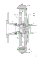
Fig. 1 is the vertical cross-sectional schematic of whole pulverizer of having used the distributor wheel disc according to the present invention;
Fig. 2 is according to the vertical cutaway view Amplified image of distributor wheel disc of the present invention;
Fig. 3 is the cutaway view along Fig. 2 center line III-III;
Fig. 4 is arranged on the blade stereogram at each place, impelling hole on the distributor wheel disc;
Fig. 5 is the view identical with Fig. 3, is illustrated in the self-insurance sheath that forms in the pulverizer duration of work distributor wheel disc;
Fig. 6 is the impelling blade front view of seeing along arrow F direction among Fig. 5;
Fig. 7 is the cutaway view along Fig. 6 center line VII-VII.
Cylindrical vessel 1 as can be seen from Figure 1 with vertical axis, at this container top a heavy in section vertical pipe 2 is arranged, an arm 3 that links to each other with the vavuum pump (not shown) is arranged on it, and hopper 4 and 5 is arranged in the pipeline 2, and wherein hopper 5 links to each other with vibrator 6.
Below vibrating bunker 5, dispose one and supplied with the hopper 7 of wanting material crushed, want material crushed from axial outlet opening, to discharge, enter the central feeding chamber 21 of the distributor wheel disc 20 that constitutes pulverizer runner upper part, the radial directed passage that a plurality of regular distribution are arranged in this wheel disc, for example 22 and 23.
The impact surface of crash panel 8 by one deck wear-resistant and impact-resistant material topped, it and each passage are arranged in around the container accordingly.
Formed an area of space between the outer fringe surface of wheel disc 20 and crash panel 8, the pellet that pulverize is gone into this zone with impelling.Below this area of space, is furnished with a vibrating bunker 10, be ground into dusty material with collection, for the dusty material after will processing is delivered to outlet 11, this outlet and an air lock arrangement are connected together, this air-lock can make material crushed outflow under vacuum action, and don't destroys the vacuum in the container.
The wheel disc 20 that constitutes the pulverizer upper part is fixed on the tubular cylinder axle of a prolongation, and rotation together.Axle 12 is driven by motor 13 and is led and supporting by a cover journal bearing and thrust bearing component 14.
Motor 13 makes wheel disc 20 with very high speed rotation.
In Fig. 2, distributor wheel disc 20 is to amplify expression.This wheel disc inside is provided with a feed space 21 and two passages 22 and 23, and the inside end of passage leads to feed space 21, and an outside end leads to the wheel disc outer rim through impelling hole 24 and 25.
Hopper 7 is arranged on distributor wheel disc 20 axis, is communicated with the feed space 21 of this wheel disc.This distributor wheel disc 20 is made up of disc loam cake 26 and chassis 27, and these two parts are secured together mutually, and is driven with very high speed rotation by axle 12.
After bulk material enters feed space 21, under centrifugal action, pass passage 22 and 23 and gone out by outside impelling.The particles hit that is gone out by impelling is broken into fine powder on crash panel 8.
Because bulk material, for example the coal after cement or the pulverizing is exactly an abrasive material simply when handling in cintrifugal disintegrator, and not only the wearing and tearing of the pulverizer impelling passage outer rim port of export are rapid, and the wearing and tearing of impelling vias inner walls are also very fast.
For fear of passage 22 and 23 inner wall abrasion; the shape (referring to Fig. 3) of the curve A that pellet spigot surface 22a in passage separately and 23a have regulation; that is to say; the bending direction of this curve is consistent with the direction of rotation of distributor wheel disc; the profile of this passage is that the coefficient of friction according to two kinds of materials that are in contact with one another calculates carefully; and can on described curve A, form stable self-insurance sheath 28(that one deck is made of bulk material self referring to Fig. 5), it again can automatic regeneration in the time of along with described protective layer wearing and tearing.
Because the shape facility that bulk material spigot surface 22a and 23a are had; one deck pellet accumulation horizon generates in each passage 22 and 23; become up to the pellet accumulation horizon till the shape of curve B, this fixedly protective layer that is formed by pellet has just constituted the effective protection aquiclude to described spigot surface in such a way.
Yet at each channel end 22b and 23b place, the thickness of this self-insurance sheath 28 is as many as zero, so this position is to suffer high-wearing rapid wear bad block.
The present invention can avoid wearing and tearing occurring in this zone.
In order to realize this purpose, be provided with the part that a total label 30 of usefulness is represented at each passage 22 of distributor wheel disc 20 and 23 outlet 24 and 25 places, end.
This part be by one be fastened on the wheel disc 20 or and the blade that is made of one of wheel disc constitute.
In an embodiment, this blade 30 is that the extension by chassis 27 lateral surfaces constitutes, in such a way, just can in the plane vertical, form a vertical wall 31 with plane, distributor wheel disc 20 place, this vertical wall 31 is positioned at the downstream of outlet 24, and forms a chamber 32 in described terminal 22b back.
In this chamber 32, pasting vertical wall 31 first deflection plate 33 that is made of an independent little metallic plate has been installed.The top of first deflection plate 33 is triangular in shape, and its summit 33a up and exceed vertical wall 31.
In addition, second deflection plate 34 that also has an independent little metallic plate to constitute also is installed in this chamber 32.This second deflection plate 34 and first deflection plate 33 are settled back-to-back.Second deflection plate, 34 tops are also triangular in shape, its summit 34a also up, its height is less than the height of the first deflection plate summit 33a.
In an embodiment, two deflection plates 33 and 34 side are crooked, and the center of curvature of its curve overlaps with distributor wheel disc center O on the rotation.In addition as can be seen from Figure 3, on the same radius OX that each deflection plate 33 and 34 summit 33a and the floor projection of 34a in the horizontal plane of wheel disc 20 were positioned at wheel disc 20 center O points.
Above-mentioned two deflection plates 33 and 34 side also can be perpendicular to the plane of radius OX.
The blade that is positioned at passage 23 exits is identical with the blade that is positioned at passage 22 exits.
When distributor wheel disc 20 had two opposed symmetric channels 22 and 23, the deflection plate 33 of each blade and 34 summit 33a and 34a were on the same diameter XOX ' of this wheel disc 20.
In addition, distributor wheel disc 20 also has the device 40(of the starting point that is used to be adjusted in the stable self-insurance sheath 28 that is formed by pellet in each passage 22 and 23 referring to Fig. 2).This device 40 is made of disk 41, and this disk is fixed on the chassis 27 and rotates together thereupon.It is following coaxial with wheel disc 20 that this device 40 is arranged on feed space 21.On disk 41, have the fan-shaped projecting block of garlands shape fritter (42,43 ...).
The number of the fan-shaped projecting block of fritter on the disk 41 equates with the number of active lanes that distributor wheel disc 20 is had.In an embodiment, distributor wheel disc 20 has two symmetric channels, so disk 41 has the little fan- shaped projecting block 42 and 43 of two diametrically contrapositions.Little fan-shaped projecting block 42 is corresponding to passage 22, and little fan-shaped projecting block 43 is corresponding to passage 23.
The position of disk 41 is adjustable; the entry position of little fan-shaped projecting block can be changed with such way, thereby the starting point of the self-insurance sheath that forms in each passage can be adjusted at according to the coefficient of friction between the granular size of processed material and the material that is in contact with one another with respect to passage 22 and 23.
As mentioned above, in the course of work of pulverizer, in each passage 22 and 23, constantly form pellet accumulation horizon 28, till the shape of the curved B of accumulation horizon.Like this, this fixing curved surface that is made of pellet just can form effective protection to spigot surface.
In the pulverizer course of work, the pellet that enters feed space 21 also can form the granulation mass lamination 50 of an inclination on second deflection plate 34 of each blade 30, and it has extended the curve B of protective layer 28.The length of this accumulation horizon 50 depends on the length of second deflection plate 34, and the length of second deflection plate 34 is to determine with such method: the thickness of the pellet self-insurance sheath that terminal 22b that make in each passage 22 and 23 and 23b place form is enough to prevent occur wearing and tearing in this end.
Because second deflection plate is triangular in shape, the shape of accumulation horizon 50 is acclivitous dihedrons, forms two and intersects at QT(referring to Fig. 6) half- plane 50a and 50b.
Above this oblique accumulation horizon 50, also form the second oblique accumulation horizon 51 that a pellet piles on first deflection plate 33.Because deflection plate 33 is also triangular in shape, the shape of accumulation horizon 51 also is acclivitous dihedron, forms two the half-plane 51a and the 51b that intersect at TS.The half-plane TSV of this dihedron 51 has formed a boundary layer, and like this, the projection of the normal component in this boundary layer in wheel disc 20 planes will be opposite substantially with the direction of rotation ω of this wheel disc 20.
After inclination accumulation horizon 50 and 51 on the protective layer 28 in each passage 22 and 23 and the deflection plate 33 and 34 of each blade 30 forms; the particle of wanting material processed that feed space 21 by distributor wheel disc 20 imports will produce motion, and the general at first slip over above the quilt particle layer of intercepting and capturing between curved surface A and B.
When pellet arrives the half-plane 50a of accumulation horizon 50, because due to the shape of this accumulation horizon, these particles will be blocked and change the motion height, present towards the motion of OX direction, so just can avoid these particles directly to be gone out by impelling.
Like this, the pellet half-plane TSV that will reach accumulation horizon 51 goes up the height that T is ordered.Because the projection of normal component in plane, wheel disc 20 place of TSV half-plane is opposite substantially with the direction of rotation of this wheel disc, contact force in half-plane TSV between pellet and the wheel disc will be cancelled, and pellet and wheel disc leave, thereby just can not produce wearing and tearing at these positions.
In addition, because the pellet transporting velocity that the rotation of distributor wheel disc 20 produces is more much bigger than the relative sliding velocity between this pellet in the TSV half-plane and wheel disc, therefore this relative velocity is negligible with respect to this transporting velocity, level will be recovered in pellet impelling path, exit on the TSV plane like this, then directive crash panel (8).
According to the difference of the granule size of the character of impelling material and the product that goes for, distributor wheel disc 20 must have higher or lower rotating speed.Because the adhesive force of pellet and the rotating speed of wheel disc are irrelevant, so can both form protective layer in all cases.
Self-insurance sheath in passage, at channel end exit and blade place forms by product itself, has therefore avoided the generation of any wearing and tearing, has kept the sufficiently high rotating speed of distributor wheel disc again simultaneously, to obtain needed product granularity.
In addition; according to coefficient of friction that is in contact with one another material and the difference of wanting the granular size of material crushed; can change the position of little secter pat 42 on it and 43 by the way that disk 41 is rotated towards or another direction; thereby change the starting point of protective layer 28 in passage 22 and 23; can obtain the position of desired starting point Q in this way, and can form the due care layer that to avoid any wearing and tearing at channel end 22b and 23b place.
At last, the deflection plate 33 and 34 of blade 30 is installed, can according to the granular size of coefficient of friction that is in contact with one another material and material to be processed adjust deflection plate laterally and/or the vertical position, with the geometry that changes accumulation horizon 50 and 51 and radius OX and/or OX ' with respect to the end 22b of passage 22 and 23 and the position of 23b.
The invention is not restricted to embodiment described above, under the situation of the scope that does not exceed claim, also can make other improvement and modification.
Also can form blade by two independent deflection plates, also be feasible and in fact two deflection plates are made one.Deflection plate also can be fastened on the wheel disc 26 rather than be fastened on the chassis 27.Also can allow the summit 33a of deflector 33 and 34 and 34a down, particle will be dished out below distributor wheel disc 20 in this structure.This structure is advantageous, does not in fact also have the particle after the fragmentation to fall back to loam cake, has caused the danger of this loam cake and the undesired rapid wearing and tearing of wheel disc outer rim.
Claims (11)
1; a kind of wheel for vacuum projection grinder; this wheel disc is driven in rotation; in order to bulk material to high-speed project on the crash panel (8); this wheel disc comprises a loam cake (26) and a chassis (27); between them, dispose feed space (21) and some passages (22; 23); the trend of this passage is perpendicular to the axis direction of this wheel disc (20); through outlet opening (24; 25) lead to the outside; the spigot surface 22a of this passage; the contour curve (A) that 23a respectively has the coefficient of friction of two kinds of materials that a basis is in contact with one another to calculate; form the stable self-insurance sheath (28) that one deck is made of pellet itself to go up at this curve (A); it is characterized in that: described wheel disc also is included in each outlet opening (24 of passage; the blade (30) that the plane with wheel disc (20) of downstream part 25) is vertical; this vanes fixed goes up and rotates thereupon at wheel disc (20); it on the one hand can be at each passage (22; 23) spigot surface (22a; end (22b 23a); 23b) form the protective layer that one deck is made of pellet self; and described stable self-insurance sheath (28) extended, on the other hand again can the ejection of material grain and impelling eliminate before to crash panel (8) expect and wheel disc (20) between contact force.
2, pulverizer wheel disc according to claim 1; it is characterized in that: be arranged on passage (22; 23) each outlet opening (24; 25) downstream part blade (30) is by at least one deflection plate (33; 34) constitute; described deflection plate (33; 34) can be at each passage (22; 23) spigot surface (22a; 23a) outside, end forms the self-shield accumulation horizon (50 that is made of pellet itself; 51), its geometry and inclination angle can be according to the granular size decisions of coefficient of friction that is in contact with one another material and processed material.
3, pulverizer wheel disc according to claim 1 and 2 is characterized in that: described blade (30) is to be made of two not contour deflection plates of juxtaposed triangle (33,34).
4, pulverizer wheel disc according to claim 3, it is characterized in that each triangle deflection plate (33,34) summit (33a, 34a) projection in distributor wheel disc (20) plane, place was positioned on the same radius (OX) of this wheel disk center (O), and be arranged in each passage (22,23) (22a, the downstream part of direction is flowed out in end 23a) to spigot surface with respect to the interior bulk material of distributor wheel disc (20).
5, pulverizer wheel disc according to claim 3 is characterized in that the side surface of triangle deflection plate (33,34) has definite contour curve, and the center (O) of distributor wheel disc (20) overlaps on the center of curvature of this curve and the rotation.
6, pulverizer wheel disc according to claim 3, it is characterized in that triangle deflection plate (33,34) the side be shaped as the plane, (33a, the radius of distributor wheel disc 34a) is vertical with summit by this deflection plate on this plane.
7, pulverizer wheel disc according to claim 3 is characterized in that by the formed pellet accumulation horizon (50 of two deflection plates (33,34), 51) top that is positioned at another in, and two accumulation horizons all are the dihedron shape, each self-forming two half-planes (50a, 50b; 51a, 51b), their intersections (QT) separately are positioned at and vertical plane, distributor wheel disc (20) plane, place with (TS), and the summit by two triangle deflection plates (33,34) (33a, 34a).
8, pulverizer wheel disc according to claim 7, the half-plane (51a) that it is characterized in that accumulation horizon (51) has formed a stable pellet boundary layer, and the projection of the normal component in this boundary layer in distributor wheel disc (20) plane, place is opposite substantially with the direction of rotation of this wheel disc.
9, pulverizer wheel disc according to claim 2, it is characterized in that blade (30) is that chassis (27) with distributor wheel disc (20) is made of one, or fastening thereon, and deflection plate (33,34) (33a is up with respect to this wheel disc plane 34a) on summit.
10, according to the described pulverizer wheel disc of claim 2, it is characterized in that blade (30) is that loam cake (26) with distributor wheel disc (20) is made of one, or fastening thereon, and deflection plate (33,34) (33a is down with respect to this plane, wheel disc place 34a) on summit.
11, according to the described pulverizer wheel disc of claim 3, the horizontal and/or vertical position that it is characterized in that deflection plate (33,34) is to regulate according to the granular size difference of handling material.
Applications Claiming Priority (2)
| Application Number | Priority Date | Filing Date | Title |
|---|---|---|---|
| FR8601774 | 1986-02-10 | ||
| FR8601774A FR2594048B1 (en) | 1986-02-10 | 1986-02-10 | VACUUM PROJECTION GRINDER WHEEL. |
Publications (2)
| Publication Number | Publication Date |
|---|---|
| CN87101899A CN87101899A (en) | 1987-09-02 |
| CN1009439B true CN1009439B (en) | 1990-09-05 |
Family
ID=9331965
Family Applications (1)
| Application Number | Title | Priority Date | Filing Date |
|---|---|---|---|
| CN87101899A Expired CN1009439B (en) | 1986-02-10 | 1987-02-09 | Wheel for vacuum projection grinder |
Country Status (9)
| Country | Link |
|---|---|
| US (1) | US4738403A (en) |
| EP (1) | EP0233812B1 (en) |
| CN (1) | CN1009439B (en) |
| AT (1) | ATE67691T1 (en) |
| AU (1) | AU594116B2 (en) |
| CA (1) | CA1264555A (en) |
| DE (1) | DE3773224D1 (en) |
| FR (1) | FR2594048B1 (en) |
| ZA (1) | ZA87911B (en) |
Families Citing this family (14)
| Publication number | Priority date | Publication date | Assignee | Title |
|---|---|---|---|---|
| GB8727231D0 (en) * | 1987-11-20 | 1987-12-23 | Impact Technology Ltd | Machine for comminuting materials |
| US4923131A (en) * | 1988-06-06 | 1990-05-08 | Rossouw Pieter J | Rotary impact crusher rotor |
| JP2936382B2 (en) * | 1994-11-28 | 1999-08-23 | コトブキ技研工業株式会社 | Reinforcing material for centrifugal crusher and crushed material supply port |
| US5860605A (en) | 1996-10-11 | 1999-01-19 | Johannes Petrus Andreas Josephus Van Der Zanden | Method and device for synchronously making material collide |
| NZ328061A (en) * | 1997-06-11 | 1998-11-25 | Svedala Barmac Ltd | Rotary mineral crusher with focused output of the rotor includes a tip component engageable via a holder to define a transverse weir that is not symmetrical in a plane transverse to the radial direction |
| NZ328062A (en) * | 1997-06-11 | 1999-10-28 | Svedala Barmac Ltd | Rotary mineral breakers having a contoured bed and weir |
| US6405953B1 (en) | 1999-07-30 | 2002-06-18 | Impact Service Corporation | Impeller shoe for an impact crusher |
| DE10057433A1 (en) * | 2000-11-20 | 2002-05-23 | Bhs Sonthofen Maschinen & Anlagenbau Gmbh | Centrifugal mill has two chambers, and inner radial end of blade wall of two blades when both break-off edges are joined and mean perpendicular is formed on connecting line, lies in vicinity of this mean perpendicular |
| US6820735B1 (en) * | 2002-07-02 | 2004-11-23 | Src Innovations, Llc | Bagging machine rotor tooth having a concave face |
| AU2003283954A1 (en) * | 2002-12-06 | 2004-06-30 | Cornerstone Technologies, L.L.C. | High g mill in a blending and drying system |
| EP2666543B1 (en) * | 2012-05-23 | 2020-04-08 | Sandvik Intellectual Property AB | Vertical shaft impact crusher feed tube |
| EP2821141B1 (en) * | 2013-07-02 | 2016-10-12 | Sandvik Intellectual Property AB | VSI-crusher feed hopper distribution device |
| CN110237898A (en) * | 2019-05-08 | 2019-09-17 | 辉县市新科机械设备有限公司 | Vacuum pulverizer |
| CN116550209B (en) * | 2023-05-24 | 2024-04-12 | 广东海诚高新科技有限公司 | Cationic surface sizing agent and preparation device and method thereof |
Family Cites Families (6)
| Publication number | Priority date | Publication date | Assignee | Title |
|---|---|---|---|---|
| US3174697A (en) * | 1962-07-30 | 1965-03-23 | Adams Engineering | Impeller |
| US3970257A (en) * | 1972-10-05 | 1976-07-20 | Macdonald George James | Apparatus for reducing the size of discrete material |
| FR2283726A2 (en) * | 1974-09-06 | 1976-04-02 | Air Liquide | Rotary mill for fragmenting plastics materials - with vane profile modified to minimise friction and erosion losses |
| FR2412348A1 (en) * | 1977-12-20 | 1979-07-20 | Creusot Loire | Centrifugal pulveriser projecting particles onto blade targets - which pivot to present opposite faces to particles depending on rotational direction of centrifuge |
| NZ201190A (en) * | 1982-08-07 | 1986-07-11 | Barmac Ass Ltd | Additional wear tip for rotary mineral breaker |
| FR2577445B1 (en) * | 1985-02-15 | 1988-05-27 | Framatome Sa | SOLID PARTICLE PROJECTION DEVICE FOR VACUUM CENTRIFUGAL CRUSHER |
-
1986
- 1986-02-10 FR FR8601774A patent/FR2594048B1/en not_active Expired
-
1987
- 1987-01-26 DE DE8787400175T patent/DE3773224D1/en not_active Expired - Lifetime
- 1987-01-26 EP EP87400175A patent/EP0233812B1/en not_active Expired - Lifetime
- 1987-01-26 AT AT87400175T patent/ATE67691T1/en not_active IP Right Cessation
- 1987-01-28 CA CA000528374A patent/CA1264555A/en not_active Expired - Lifetime
- 1987-02-03 AU AU68271/87A patent/AU594116B2/en not_active Ceased
- 1987-02-09 ZA ZA87911A patent/ZA87911B/en unknown
- 1987-02-09 CN CN87101899A patent/CN1009439B/en not_active Expired
- 1987-02-10 US US07/013,086 patent/US4738403A/en not_active Expired - Fee Related
Also Published As
| Publication number | Publication date |
|---|---|
| DE3773224D1 (en) | 1991-10-31 |
| US4738403A (en) | 1988-04-19 |
| EP0233812B1 (en) | 1991-09-25 |
| CA1264555A (en) | 1990-01-23 |
| ZA87911B (en) | 1987-09-30 |
| FR2594048B1 (en) | 1988-05-27 |
| AU594116B2 (en) | 1990-03-01 |
| AU6827187A (en) | 1987-08-13 |
| ATE67691T1 (en) | 1991-10-15 |
| EP0233812A2 (en) | 1987-08-26 |
| CN87101899A (en) | 1987-09-02 |
| EP0233812A3 (en) | 1989-01-04 |
| FR2594048A1 (en) | 1987-08-14 |
Similar Documents
| Publication | Publication Date | Title |
|---|---|---|
| CN1009439B (en) | Wheel for vacuum projection grinder | |
| US3970257A (en) | Apparatus for reducing the size of discrete material | |
| US4225092A (en) | Annular grinding mill | |
| CN1103335A (en) | Screening machine | |
| CN102300647B (en) | Device for selective granulometric separation of solid powdery materials using centrifugal action, and method for using such device | |
| CN106964552A (en) | Interval throwing type feed separation method and device | |
| JPH036089B2 (en) | ||
| US4796822A (en) | Impeller for an impact crusher | |
| KR890002073B1 (en) | Separator for sorting particulate material | |
| WO2013141303A1 (en) | Vertical-type mill | |
| US3180582A (en) | Bowl for centrifugal pulverizer | |
| US5080235A (en) | Small particle separator | |
| US2981489A (en) | Reduction apparatus | |
| US4515316A (en) | Method of withdrawing particulate material from dead-bed of centrifugal crusher and centrifugal crusher suitable for carrying the method into practice | |
| US3957213A (en) | Gyratory crusher with material distribution means | |
| US4682739A (en) | Device for projecting solid particles for a vacuum centrifugal grinder | |
| JPS60150847A (en) | Crusher and impeller assembly | |
| US7036759B2 (en) | Autogenous rotor | |
| US20020076308A1 (en) | Chip diffuser | |
| CN206997090U (en) | Throwing type material separation device | |
| CN1163304C (en) | Method and device for fragmenting bulk materials | |
| US3989620A (en) | Rotary distributor plate for a centrifugal air classifier | |
| SU1011249A1 (en) | Percussion-action mill | |
| SU1734832A1 (en) | Centrifugal mill | |
| CN206997086U (en) | Rotate throwing type material separation device |
Legal Events
| Date | Code | Title | Description |
|---|---|---|---|
| C06 | Publication | ||
| PB01 | Publication | ||
| C10 | Entry into substantive examination | ||
| SE01 | Entry into force of request for substantive examination | ||
| C13 | Decision | ||
| GR02 | Examined patent application | ||
| C14 | Grant of patent or utility model | ||
| GR01 | Patent grant | ||
| C19 | Lapse of patent right due to non-payment of the annual fee | ||
| CF01 | Termination of patent right due to non-payment of annual fee |