EP0941146B1 - Dispositif de fixation d'un organe de distribution sur un col de recipient - Google Patents
Dispositif de fixation d'un organe de distribution sur un col de recipient Download PDFInfo
- Publication number
- EP0941146B1 EP0941146B1 EP97948957A EP97948957A EP0941146B1 EP 0941146 B1 EP0941146 B1 EP 0941146B1 EP 97948957 A EP97948957 A EP 97948957A EP 97948957 A EP97948957 A EP 97948957A EP 0941146 B1 EP0941146 B1 EP 0941146B1
- Authority
- EP
- European Patent Office
- Prior art keywords
- neck
- dispenser member
- fixing
- fixing element
- receptacle
- Prior art date
- Legal status (The legal status is an assumption and is not a legal conclusion. Google has not performed a legal analysis and makes no representation as to the accuracy of the status listed.)
- Expired - Lifetime
Links
Images


Classifications
-
- B—PERFORMING OPERATIONS; TRANSPORTING
- B05—SPRAYING OR ATOMISING IN GENERAL; APPLYING FLUENT MATERIALS TO SURFACES, IN GENERAL
- B05B—SPRAYING APPARATUS; ATOMISING APPARATUS; NOZZLES
- B05B11/00—Single-unit hand-held apparatus in which flow of contents is produced by the muscular force of the operator at the moment of use
- B05B11/0005—Components or details
- B05B11/0008—Sealing or attachment arrangements between sprayer and container
- B05B11/0013—Attachment arrangements comprising means cooperating with the inner surface of the container
-
- B—PERFORMING OPERATIONS; TRANSPORTING
- B05—SPRAYING OR ATOMISING IN GENERAL; APPLYING FLUENT MATERIALS TO SURFACES, IN GENERAL
- B05B—SPRAYING APPARATUS; ATOMISING APPARATUS; NOZZLES
- B05B11/00—Single-unit hand-held apparatus in which flow of contents is produced by the muscular force of the operator at the moment of use
- B05B11/01—Single-unit hand-held apparatus in which flow of contents is produced by the muscular force of the operator at the moment of use characterised by the means producing the flow
- B05B11/10—Pump arrangements for transferring the contents from the container to a pump chamber by a sucking effect and forcing the contents out through the dispensing nozzle
- B05B11/1042—Components or details
- B05B11/1043—Sealing or attachment arrangements between pump and container
- B05B11/1046—Sealing or attachment arrangements between pump and container the pump chamber being arranged substantially coaxially to the neck of the container
- B05B11/1047—Sealing or attachment arrangements between pump and container the pump chamber being arranged substantially coaxially to the neck of the container the pump being preassembled as an independent unit before being mounted on the container
-
- B—PERFORMING OPERATIONS; TRANSPORTING
- B65—CONVEYING; PACKING; STORING; HANDLING THIN OR FILAMENTARY MATERIAL
- B65D—CONTAINERS FOR STORAGE OR TRANSPORT OF ARTICLES OR MATERIALS, e.g. BAGS, BARRELS, BOTTLES, BOXES, CANS, CARTONS, CRATES, DRUMS, JARS, TANKS, HOPPERS, FORWARDING CONTAINERS; ACCESSORIES, CLOSURES, OR FITTINGS THEREFOR; PACKAGING ELEMENTS; PACKAGES
- B65D47/00—Closures with filling and discharging, or with discharging, devices
- B65D47/04—Closures with discharging devices other than pumps
- B65D47/06—Closures with discharging devices other than pumps with pouring spouts or tubes; with discharge nozzles or passages
Definitions
- the present invention relates to a fixing device a dispensing member, such as a pump, on the neck of a container containing product to be dispensed More in particular, the present invention relates to fixing devices for distributors in which the pump is not attached to the container with a ring of external fixing which comes to snap or crimp on the neck of the container.
- Such fastening devices are known in the state of the art.
- the document FR-2 719 292 discloses such a fixing device a dosing device in a container containing product to be dispensed, in which the pump body is fixed directly into the container neck using a ferrule which is fitted inside said pump body, the press fitting of this ferrule in the body of pump creating a radial force which fixes the pump body in the container neck.
- This device which is well suited for some dispensers, may be insufficient or unsuitable for other types of distributors.
- the device of document FR-2 719 292 does not not adapt because the outside diameter of the pump body should approximately match the inside diameter of the neck of the container.
- this device allows compensate for manufacturing tolerances as well of the collar container than from the pump body, this compensation is limited due to the materials used for the body of the container (usually glass) and for the pump body (usually a rigid plastic material).
- Document FR-2 699 433 discloses a device for mounting intended to be easily mounted and dismountable from similar to a tapered plug. These measures has a rigid ring attached to the pump body and a or more sockets made of flexible material to adapt to necks of different diameters. Because the device must be easily removable, it does not allow secure fixing and guarantee perfect seal.
- a device having the characteristics of the preamble of claim 1 is known from the document DE-C-804 839.
- the object of the present invention is to provide a fastening device that overcomes the disadvantages above, while providing the same benefits, to know a cost saving for manufacturing and mounting of the product dispenser. This limitation of costs is particularly attractive when the distributor is a sample, such as a sample of perfume, which must be distributed free of charge.
- the present invention also aims to provide a such fixing device which allows to adapt the same dispensing member in containers having necks of different diameters.
- the present invention also aims to provide a such fastening device which is perfectly safe and waterproof.
- the fixing device must not not be easily removable.
- the present invention provides a fixing device according to claim 1.
- the fixing element is a ferrule whose outside diameter corresponds approximately to the diameter inside the neck of the container and whose diameter interior is, before fitting of the distribution, less than the outside diameter of the body the distribution body.
- said fixing element comprises a radial flange at its upper end which rests on the top of the container neck, said flange retaining the fastening element during the fitting of the member of distribution.
- said gripping means comprise a or more bulges of material which, before fitting of the dispensing member protrude towards the interior of said fastener, and which, when the fitting of said distribution member is forced under the container neck by the body of the distribution.
- the body of the dispensing member has a reduced diameter lower part which has little or no effect on said gripping means so that the interaction between the distributor and the said gripping means takes place only at the end of fitting.
- said means grip are made in the form of legs comprising each at their lower end a bulge of deformable material.
- said means for taken are made in the form of a bulge annular deformable material provided at the lower end of the fixing element.
- the body of the dispensing member has an external groove which, in the assembled state of the device after fitting of the dispensing member, is located at the level of said gripping means, a portion said gripping means being received in said groove for fix the distribution member with respect to said distribution member fixation.
- the fixing element is produced in a deformable flexible material such as polyethylene or a thermoplastic elastomer.
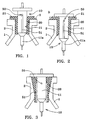
- the invention relates to a fixing device for a dispensing member 10, such that a pump comprising a body 11, in the neck 2 of a container 1.
- This device fixing comprises a single fixing element 20 produced of deformable material, placed in the neck 2 of the container 1 between said neck 2 of the container and said pump body 11.
- Said fastening element 20 is preferably made in a flexible and deformable material such as polyethylene or an elastomeric thermoplastic.
- This fastening element 20 comprises, before mounting, an outside diameter corresponding approximately to the diameter inside of container neck 2, and an inside diameter slightly smaller than the outside diameter of the pump body 11.
- said fixing element 20 is deformed and / or compressed by fitting the pump body 11 into the neck 2 of the container, so that it exerts a radial force both on said pump body 11 and on said neck 2 of the container, said radial force ensuring tight fixing from the pump into the container.
- the fixing element 20 is produced in the form of a cylindrical shell, which comes to adapt on and in the cylindrical neck 2 of a container 1, usually glass.
- This cylindrical shell 20 comprises advantageously a radial flange 21 at its end upper, that is to say its end disposed at the level of the top 3 of neck 2 of container 1.
- This ferrule 20 in the container covers part or all of the neck height 2.
- the pump body 11 may include a part lower diameter 11a which does not cooperate with said fastening element 20 during fitting. So, when the pump 10 is inserted into the neck of the container, the fixing element 20 is advantageously deformed and / or compressed only by the largest diameter part of the body pump 11, i.e. for only part of the fitting. This deformation and / or compression creates a radial force exerted on the inner wall of the neck of the container and on the pump body. When the attachment is in the assembled state, as shown in the Figure 2, the pump 10 is held in place by said radial force exerted by the ferrule 20.
- the radial flange 21 useful for holding the ferrule 20 in place on the container neck when fitting the pump body.
- FIG 3 there is shown another variant of a fixing device where the invention applies.
- the inner surface of the neck 2 of the container 1 is not cylindrical but frustoconical and the element of fastener 20 has a corresponding shape so that a flange radial as described in the embodiment shown in Figures 1 and 2, is not necessary here.
- the fastening element 20 is held automatically in place in col 2 when the fitting of the pump body 11.
- the pump body 11 may include a vent hole 50.
- This vent hole 50 can be arranged in the upper part of the pump body 11 and be connected to the container by a groove 51 or any other equivalent means.
- This groove 51 can be produced in the pump body 11 (fig. 1 and 2) or in the fixing element 50 (fig. 3).
- FIGS. 4 and 5 An embodiment according to the invention is shown in Figures 4 to 9.
- the element of fixing 20 has at its lower end means socket 25 adapted to fix the fixing element 20, to the assembled state of the device, under the neck 2 inside the container 1.
- the example shown in Figures 4 and 5 has a cylindrical ferrule 20 which fits in a neck 2 of also cylindrical container.
- this embodiment of FIGS. 4 and 5 also adapts in the embodiment of Figure 3, where the inside of the neck of the container is frustoconical.
- the means of grip 25 have one or more bulges of material which, before fitting of the distribution member, that is to say from the pump, protrude inward from the fastening element 20, and which during the fitting of the pump 10 are forced under the neck 2 of the container 1 by the pump body 11, as shown in FIG. 5.
- gripping means 25 can be produced either under the shape of legs each having at its end lower a bulge of deformable material, either under the form of an annular bulge made of deformable material at the lower end of the fixing element 20.
- the pump body 11 comprises a part lower diameter reduced 11a which does not cooperate or little with said means of grip 25.
- Figures 6 to 9 show a first variant of the device of FIGS. 4 and 5.
- the neck 2 has a peripheral rib 5 intended to allow embedding the flange 21 of the fixing member 20 as well as the pump flange 10.
- the neck 2 also includes a part frustoconical 6 flaring outwards at the end upper part of the inner surface of the neck 2.
- This part frustoconical 6 cooperates with the corresponding part of the fixing member 20 to ensure total tightness after fitting of the pump body 11. Indeed, by the fitting, the fixing member 20 is pulled towards inside the neck by the pump body. It is therefore created a strong seal at the top of the device, and in particular on the frustoconical part 6.
- Figures 8 and 9 show yet another variant of the fixing device according to the invention.
- the pump body 11 has a groove or groove 15, peripheral or not, which, in the assembled state of the device, is located in the neck 2 at the level of the bulges of material 25.
- this groove 15 for example by creep, for securing the pump body relative to the member fixing 20.
Abstract
Description
- la figure 1 est une vue schématique en coupe verticale d'un dispositif de fixation, à l'état semi-monté ;
- la figure 2 est une vue similaire à celle de la figure 1, à l'état monté du dispositif ;
- la figure 3 est une vue similaire à celle de la figure 2, montrant une variante d'un dispositif de fixation ;
- la figure 4 est est une vue similaire à celle de la figure 1, montrant un mode de réalisation de l'invention ;
- la figure 5 est est une vue similaire à celle de la figure 4, à l'état monté ; et
- les figures 6 à 9 sont des vues similaires aux figures 4 et 5 montrant deux variantes de réalisation du dispositif des figures 4 et 5.
Claims (9)
- Dispositif de fixation d'un organe de distribution (10), tel qu'une pompe, sur le col (2) d'un récipient (1) contenant du produit à distribuer, ledit dispositif comportant un seul élément de fixation (20), disposé dans le col (2) du récipient entre la surface intérieure dudit col du récipient et la surface extérieure du corps (11) de l'organe de distribution (10), ledit élément de fixation (20) étant à l'état monté du dispositif de fixation, déformé et/ou comprimé par l'emmanchement du corps (11) de l'organe de distribution (10) dans le col (2) du récipient, de telle sorte qu'il exerce une force radiale sur ledit corps (11) de l'organe de distribution (10) et sur ledit col (2) du récipient, l'élément de fixation (20) étant réalisé en un matériau souple déformable, ladite force radiale assurant une fixation sûre et étanche de l'organe de distribution (10) sur le col (2) du récipient, caractérisé en ce que ledit élément de fixation (20) comporte à son extrémité inférieure des moyens de prise (25) pour fixer ledit élément de fixation (20) sous le col (2) à l'intérieur du récipient (1) après emmanchement de l'organe de distribution (10).
- Dispositif selon la revendication 1, dans lequel lesdits moyens de prise (25) comportent un ou plusieurs renflements de matière qui, avant emmanchement de l'organe de distribution (10) font saillie vers l'intérieur dudit élément de fixation (20), et qui, lors de l'emmanchement dudit organe de distribution (10) sont forcés sous le col (2) du récipient par le corps (11) du corps de distribution (10).
- Dispositif selon la revendication 1 ou 2, dans lequel le corps (11) de l'organe de distribution (10) comporte une partie inférieure (11a) de diamètre réduit qui n'agit pas ou peu sur lesdits moyens de prise (25) de sorte que l'interaction entre l'organe de distribution (10) et lesdits moyens de prise (25) n'a lieu qu'en fin d'emmanchement.
- Dispositif selon l'une quelconque des revendications précédentes, dans lequel lesdits moyens de prise (25) sont réalisés sous la forme de pattes comportant chacune à leur extrémité inférieure un renflement de matière déformable.
- Dispositif selon l'une quelconque des revendications 1 à 3, dans lequel lesdits moyens de prise (25) sont réalisés sous la forme d'un renflement annulaire de matière déformable prévu à l'extrémité inférieure de l'élément de fixation (20).
- Dispositif selon l'une quelconque des revendications précédentes, dans lequel le corps (11) de l'organe de distribution (10) comporte une saignée externe (15) qui, à l'état monté du dispositif après emmanchement de l'organe de distribution (10), est située au niveau desdits moyens de prise (25), une partie desdits moyens de prise (25) étant reçue dans ladite saignée (15) pour fixer l'organe de distribution (10) par rapport audit organe de fixation (20).
- Dispositif selon l'une quelconque des revendications précédentes, dans lequel l'élément de fixation (20) est réalisé en un matériau souple déformable tel que du polyéthylène ou un thermoplastique élastomère.
- Dispositif selon l'une quelconque des revendications précédentes, dans lequel l'élément de fixation (20) est une virole dont le diamètre extérieur correspond environ au diamètre intérieur du col (2) du récipient et dont le diamètre intérieur est, avant emmanchement de l'organe de distribution (10), inférieur au diamètre extérieur du corps (11) de l'organe de distribution (10).
- Dispositif selon l'une quelconque des revendications précédentes, dans lequel ledit élément de fixation (20) comporte une bride radiale (21) à son extrémité supérieure qui repose sur le dessus (3) du col (2) du récipient (1), ladite bride (21) retenant l'élément de fixation (20) lors de l'emmanchement de l'organe de distribution (10).
Applications Claiming Priority (3)
| Application Number | Priority Date | Filing Date | Title |
|---|---|---|---|
| FR9614639A FR2756546B1 (fr) | 1996-11-29 | 1996-11-29 | Dispositif de fixation d'un organe de distribution sur un col de recipient |
| FR9614639 | 1996-11-29 | ||
| PCT/FR1997/002155 WO1998023391A2 (fr) | 1996-11-29 | 1997-11-28 | Dispositif de fixation d'un organe de distribution sur un col de recipient |
Publications (2)
| Publication Number | Publication Date |
|---|---|
| EP0941146A1 EP0941146A1 (fr) | 1999-09-15 |
| EP0941146B1 true EP0941146B1 (fr) | 2003-04-23 |
Family
ID=9498158
Family Applications (1)
| Application Number | Title | Priority Date | Filing Date |
|---|---|---|---|
| EP97948957A Expired - Lifetime EP0941146B1 (fr) | 1996-11-29 | 1997-11-28 | Dispositif de fixation d'un organe de distribution sur un col de recipient |
Country Status (6)
| Country | Link |
|---|---|
| US (1) | US6279786B1 (fr) |
| EP (1) | EP0941146B1 (fr) |
| DE (1) | DE69721294T2 (fr) |
| ES (1) | ES2198012T3 (fr) |
| FR (1) | FR2756546B1 (fr) |
| WO (1) | WO1998023391A2 (fr) |
Families Citing this family (35)
| Publication number | Priority date | Publication date | Assignee | Title |
|---|---|---|---|---|
| FR2776991B1 (fr) * | 1998-04-03 | 2000-06-09 | Teleplastics Ind | Dispositif de distribution de produits fluides |
| FR2779419B1 (fr) * | 1998-06-09 | 2000-07-28 | Qualipac Sa | Adaptateur pour le montage sur un flacon de verre d'une pompe vaporisateur |
| FR2792295B1 (fr) * | 1999-04-16 | 2001-06-22 | Valois Sa | Organe de fixation pour distributeur de produit fluide et distributeur comportant un tel organe |
| FR2798366B1 (fr) * | 1999-09-15 | 2002-01-18 | Valois Sa | Dispositif de distribution a bague de fixation emmanchee |
| FR2810301B1 (fr) * | 2000-06-16 | 2002-09-13 | Rexam Sofab | Dispositif de reprise d'air statique pour distributeur de produit liquide |
| US6592010B2 (en) * | 2001-03-22 | 2003-07-15 | Valois S.A. | Fluid dispenser |
| FR2822452B1 (fr) * | 2001-03-22 | 2003-08-15 | Valois Sa | Distributeur de produit fluide |
| DE10130368A1 (de) | 2001-06-23 | 2003-01-16 | Pfeiffer Erich Gmbh & Co Kg | Spender zum Austragen eines fluidischen Mediums |
| US7255248B2 (en) * | 2002-08-29 | 2007-08-14 | Emsar, Inc. | Plug style pump |
| FR2845355B1 (fr) * | 2002-10-07 | 2005-09-09 | Valois Sas | Distributeur de produit fluide |
| US20040069812A1 (en) * | 2002-10-07 | 2004-04-15 | Valois S.A.S. | Fluid dispenser |
| FR2847561B1 (fr) * | 2002-11-27 | 2005-08-19 | Rexam Dispensing Sys | Pompe suceptible d'obturer le col d'un flacon et conditionnement de produit a pulveriser comprenant ladite pompe et un flacon |
| FR2853567B1 (fr) * | 2003-04-09 | 2006-06-23 | Rexam Dispensing Sys | Pulverisateur comprenant une pompe formant bouchon |
| FR2857334B1 (fr) * | 2003-07-10 | 2006-08-04 | Valois Sas | Procede d'assemblage de distributeur de produit fluide. |
| FR2880001B1 (fr) * | 2004-12-23 | 2011-01-21 | Valois Sas | Distributeur de produit fluide. |
| EP2077132A1 (fr) | 2008-01-02 | 2009-07-08 | Boehringer Ingelheim Pharma GmbH & Co. KG | Dispositif distributeur, dispositif de stockage et procédé pour la distribution d'une formulation |
| US8376192B2 (en) * | 2008-03-24 | 2013-02-19 | Mary Kay Inc. | Apparatus for dispensing fluids using a press-fit diptube |
| US10011906B2 (en) | 2009-03-31 | 2018-07-03 | Beohringer Ingelheim International Gmbh | Method for coating a surface of a component |
| EP3508239B1 (fr) | 2009-05-18 | 2020-12-23 | Boehringer Ingelheim International GmbH | Adaptateur, dispositif d'inhalation et pulvérisateur |
| US10016568B2 (en) | 2009-11-25 | 2018-07-10 | Boehringer Ingelheim International Gmbh | Nebulizer |
| UA107097C2 (en) | 2009-11-25 | 2014-11-25 | Бьорінгер Інгельхайм Інтернаціональ Гмбх | Dispenser |
| WO2011064163A1 (fr) | 2009-11-25 | 2011-06-03 | Boehringer Ingelheim International Gmbh | Nébuliseur |
| EP2585151B1 (fr) | 2010-06-24 | 2018-04-04 | Boehringer Ingelheim International GmbH | Nébuliseur |
| WO2012130757A1 (fr) * | 2011-04-01 | 2012-10-04 | Boehringer Ingelheim International Gmbh | Appareil médical pourvu d'un récipient |
| US9827384B2 (en) | 2011-05-23 | 2017-11-28 | Boehringer Ingelheim International Gmbh | Nebulizer |
| FR2988377B1 (fr) * | 2012-03-21 | 2015-07-24 | Rexam Dispensing Sys | Procede de fixation d’une frette sur le col d’un flacon comprenant un organe de distribution |
| WO2013152894A1 (fr) | 2012-04-13 | 2013-10-17 | Boehringer Ingelheim International Gmbh | Pulvérisateur comprenant des moyens de détrompage |
| ES2836977T3 (es) | 2013-08-09 | 2021-06-28 | Boehringer Ingelheim Int | Nebulizador |
| WO2015018904A1 (fr) | 2013-08-09 | 2015-02-12 | Boehringer Ingelheim International Gmbh | Nébuliseur |
| US10195374B2 (en) | 2014-05-07 | 2019-02-05 | Boehringer Ingelheim International Gmbh | Container, nebulizer and use |
| WO2015169430A1 (fr) | 2014-05-07 | 2015-11-12 | Boehringer Ingelheim International Gmbh | Nébuliseur |
| KR102492824B1 (ko) | 2014-05-07 | 2023-01-30 | 베링거 인겔하임 인터내셔날 게엠베하 | 분무기, 표시 디바이스 및 컨테이너 |
| FR3024715B1 (fr) * | 2014-08-08 | 2021-06-25 | Vuitton Louis Sa | Dispositif de conditionnement pour un produit a distribuer |
| MX2018007184A (es) | 2015-12-18 | 2018-11-12 | Unilever Nv | Dispensador de aerosol. |
| IT201700082234A1 (it) * | 2017-07-19 | 2019-01-19 | Lumson Spa | Dispositivo di erogazione di una sostanza fluida |
Family Cites Families (9)
| Publication number | Priority date | Publication date | Assignee | Title |
|---|---|---|---|---|
| US1264554A (en) * | 1915-10-09 | 1918-04-30 | Anthony Peron | Device for dispensing liquids. |
| US2586687A (en) * | 1950-05-27 | 1952-02-19 | Mellon Russell | Closure cap for liquid spray containers |
| US2861839A (en) * | 1957-01-14 | 1958-11-25 | Mellon Russell | Combination container, cap and sprayer |
| US3129854A (en) * | 1961-08-21 | 1964-04-21 | Drackett Co | Dispensing device |
| FR2661157B1 (fr) * | 1990-04-19 | 1993-08-13 | Jumel Bernard | Systeme doseur sans bague destine a etre emmanche a force a l'interieur d'un col de recipient. |
| US5158211A (en) * | 1990-08-30 | 1992-10-27 | Philip Meshberg | Fluid dispensing unit retainer |
| US5277340A (en) * | 1992-11-05 | 1994-01-11 | Risdon Corporation | Dispensing container |
| FR2699433B1 (fr) * | 1992-12-21 | 1995-03-10 | Fc2 | Dispositif de montage d'une pompe de vaporisation sur des falcons à cols rodés. |
| FR2719292B1 (fr) * | 1994-04-29 | 1996-07-12 | Valois Sa | Dispositif et procédé de fixation d'un organe de dosage dans un récipient contenant du produit à distribuer. |
-
1996
- 1996-11-29 FR FR9614639A patent/FR2756546B1/fr not_active Expired - Fee Related
-
1997
- 1997-11-28 DE DE69721294T patent/DE69721294T2/de not_active Expired - Fee Related
- 1997-11-28 US US09/308,940 patent/US6279786B1/en not_active Expired - Fee Related
- 1997-11-28 ES ES97948957T patent/ES2198012T3/es not_active Expired - Lifetime
- 1997-11-28 EP EP97948957A patent/EP0941146B1/fr not_active Expired - Lifetime
- 1997-11-28 WO PCT/FR1997/002155 patent/WO1998023391A2/fr active IP Right Grant
Also Published As
| Publication number | Publication date |
|---|---|
| FR2756546A1 (fr) | 1998-06-05 |
| WO1998023391A3 (fr) | 2002-09-26 |
| DE69721294D1 (de) | 2003-05-28 |
| WO1998023391A2 (fr) | 1998-06-04 |
| US6279786B1 (en) | 2001-08-28 |
| DE69721294T2 (de) | 2004-02-19 |
| ES2198012T3 (es) | 2004-01-16 |
| FR2756546B1 (fr) | 1999-01-29 |
| EP0941146A1 (fr) | 1999-09-15 |
Similar Documents
| Publication | Publication Date | Title |
|---|---|---|
| EP0941146B1 (fr) | Dispositif de fixation d'un organe de distribution sur un col de recipient | |
| EP0757007B1 (fr) | Bague de fixation à double indexation | |
| EP0704251B3 (fr) | Dispositif et procédé de fixation d'un organe de recouvrement sur un récipient | |
| EP0652842B1 (fr) | Ensemble de distribution comprenant un recipient cylindrique comportant un piston | |
| EP1309499B1 (fr) | Organe de fixation pour fixer une pompe ou une valve sur un col de recipient | |
| EP1542911B1 (fr) | Organe de fixation et distributeur de produit fluide comprenant un tel organe de fixation | |
| EP3603817A1 (fr) | Montage et démontage facilité d'une pompe par rapport au réservoir | |
| EP1289858B1 (fr) | Distributeur a organe de fixation a etancheite peripherique | |
| FR2776991A1 (fr) | Dispositif de distribution de produits fluides | |
| EP0997397A1 (fr) | Organe et procédé de fixation d'un dispositif de distribution sur le col d'un réservoir et distributeur utilisant un tel organe de fixation | |
| EP1370477B1 (fr) | Distributeur de produit fluide | |
| EP1465819A1 (fr) | Dispositif de fixation d'organe de distribution sur un col de recipient | |
| EP1009682B1 (fr) | Dispositif et procede de fixation d'un organe de dosage dans un recipient contenant du produit a distribuer | |
| EP1220407A2 (fr) | Dispositif d'entrée de câble | |
| EP1289671A1 (fr) | Dispositif de reprise d'air dynamique pour distributeur de produit liquide | |
| FR2516899A1 (fr) | Dispositif pour prelever des substances pateuses dans des recipients remplis avec un gaz propulseur | |
| WO2019175513A1 (fr) | Conteneur pour produit fluide | |
| EP1219881A1 (fr) | Elément à fixer en aveugle sur une paroi | |
| WO2001023278A1 (fr) | Organe de fixation pour distributeur de produit fluide et distributeur comportant un tel organe | |
| EP1556293B1 (fr) | Organe de fixation pour fixer un organe de distribution sur une ouverture de reservoir et distributeur comprenant un tel organe de fixation | |
| FR2753178A1 (fr) | Coupelle de reception, dispositif de distribution equipe d'une telle coupelle et procede de montage et de remplissage d'un tel dispositif de distribution | |
| WO2009080984A1 (fr) | Dispositif de fixation et distributeur comprenant un tel dispositif | |
| FR3122652A1 (fr) | Élément de fermeture étanche pour contenants | |
| EP1216196B1 (fr) | Dispositif de distribution a bague de fixation emmanchee | |
| FR2820410A1 (fr) | Dispositif de distribution de produit fluide |
Legal Events
| Date | Code | Title | Description |
|---|---|---|---|
| PUAI | Public reference made under article 153(3) epc to a published international application that has entered the european phase |
Free format text: ORIGINAL CODE: 0009012 |
|
| 17P | Request for examination filed |
Effective date: 19990628 |
|
| AK | Designated contracting states |
Kind code of ref document: A1 Designated state(s): CH DE ES FR GB IT LI |
|
| 17Q | First examination report despatched |
Effective date: 20011001 |
|
| GRAH | Despatch of communication of intention to grant a patent |
Free format text: ORIGINAL CODE: EPIDOS IGRA |
|
| D17D | Deferred search report published (deleted) | ||
| GRAH | Despatch of communication of intention to grant a patent |
Free format text: ORIGINAL CODE: EPIDOS IGRA |
|
| RAP1 | Party data changed (applicant data changed or rights of an application transferred) |
Owner name: VALOIS S.A.S. |
|
| GRAA | (expected) grant |
Free format text: ORIGINAL CODE: 0009210 |
|
| AK | Designated contracting states |
Designated state(s): CH DE ES FR GB IT LI |
|
| REG | Reference to a national code |
Ref country code: GB Ref legal event code: FG4D Free format text: NOT ENGLISH |
|
| REG | Reference to a national code |
Ref country code: CH Ref legal event code: EP |
|
| REF | Corresponds to: |
Ref document number: 69721294 Country of ref document: DE Date of ref document: 20030528 Kind code of ref document: P |
|
| REG | Reference to a national code |
Ref country code: CH Ref legal event code: NV Representative=s name: BARMAG GMBH ENGINEERING AND MANUFACTURING |
|
| GBT | Gb: translation of ep patent filed (gb section 77(6)(a)/1977) | ||
| REG | Reference to a national code |
Ref country code: ES Ref legal event code: FG2A Ref document number: 2198012 Country of ref document: ES Kind code of ref document: T3 |
|
| PLBE | No opposition filed within time limit |
Free format text: ORIGINAL CODE: 0009261 |
|
| STAA | Information on the status of an ep patent application or granted ep patent |
Free format text: STATUS: NO OPPOSITION FILED WITHIN TIME LIMIT |
|
| 26N | No opposition filed |
Effective date: 20040126 |
|
| PGFP | Annual fee paid to national office [announced via postgrant information from national office to epo] |
Ref country code: CH Payment date: 20051114 Year of fee payment: 9 |
|
| PGFP | Annual fee paid to national office [announced via postgrant information from national office to epo] |
Ref country code: DE Payment date: 20061108 Year of fee payment: 10 |
|
| PGFP | Annual fee paid to national office [announced via postgrant information from national office to epo] |
Ref country code: GB Payment date: 20061110 Year of fee payment: 10 |
|
| PGFP | Annual fee paid to national office [announced via postgrant information from national office to epo] |
Ref country code: ES Payment date: 20061113 Year of fee payment: 10 |
|
| PG25 | Lapsed in a contracting state [announced via postgrant information from national office to epo] |
Ref country code: LI Free format text: LAPSE BECAUSE OF NON-PAYMENT OF DUE FEES Effective date: 20061130 Ref country code: CH Free format text: LAPSE BECAUSE OF NON-PAYMENT OF DUE FEES Effective date: 20061130 |
|
| PGFP | Annual fee paid to national office [announced via postgrant information from national office to epo] |
Ref country code: IT Payment date: 20061130 Year of fee payment: 10 |
|
| REG | Reference to a national code |
Ref country code: CH Ref legal event code: PL |
|
| GBPC | Gb: european patent ceased through non-payment of renewal fee |
Effective date: 20071128 |
|
| PG25 | Lapsed in a contracting state [announced via postgrant information from national office to epo] |
Ref country code: DE Free format text: LAPSE BECAUSE OF NON-PAYMENT OF DUE FEES Effective date: 20080603 |
|
| PG25 | Lapsed in a contracting state [announced via postgrant information from national office to epo] |
Ref country code: GB Free format text: LAPSE BECAUSE OF NON-PAYMENT OF DUE FEES Effective date: 20071128 |
|
| REG | Reference to a national code |
Ref country code: ES Ref legal event code: FD2A Effective date: 20071129 |
|
| PG25 | Lapsed in a contracting state [announced via postgrant information from national office to epo] |
Ref country code: ES Free format text: LAPSE BECAUSE OF NON-PAYMENT OF DUE FEES Effective date: 20071129 |
|
| PGFP | Annual fee paid to national office [announced via postgrant information from national office to epo] |
Ref country code: FR Payment date: 20081127 Year of fee payment: 12 |
|
| PG25 | Lapsed in a contracting state [announced via postgrant information from national office to epo] |
Ref country code: IT Free format text: LAPSE BECAUSE OF NON-PAYMENT OF DUE FEES Effective date: 20071128 |
|
| REG | Reference to a national code |
Ref country code: FR Ref legal event code: ST Effective date: 20100730 |
|
| PG25 | Lapsed in a contracting state [announced via postgrant information from national office to epo] |
Ref country code: FR Free format text: LAPSE BECAUSE OF NON-PAYMENT OF DUE FEES Effective date: 20091130 |