EP0940566A2 - Control device for the cooling - and heating circuit of an internal combustion engine - Google Patents
Control device for the cooling - and heating circuit of an internal combustion engine Download PDFInfo
- Publication number
- EP0940566A2 EP0940566A2 EP99102206A EP99102206A EP0940566A2 EP 0940566 A2 EP0940566 A2 EP 0940566A2 EP 99102206 A EP99102206 A EP 99102206A EP 99102206 A EP99102206 A EP 99102206A EP 0940566 A2 EP0940566 A2 EP 0940566A2
- Authority
- EP
- European Patent Office
- Prior art keywords
- control device
- opening
- inlet
- outlet openings
- circuit
- Prior art date
- Legal status (The legal status is an assumption and is not a legal conclusion. Google has not performed a legal analysis and makes no representation as to the accuracy of the status listed.)
- Granted
Links
Images

Classifications
-
- F—MECHANICAL ENGINEERING; LIGHTING; HEATING; WEAPONS; BLASTING
- F01—MACHINES OR ENGINES IN GENERAL; ENGINE PLANTS IN GENERAL; STEAM ENGINES
- F01P—COOLING OF MACHINES OR ENGINES IN GENERAL; COOLING OF INTERNAL-COMBUSTION ENGINES
- F01P7/00—Controlling of coolant flow
- F01P7/14—Controlling of coolant flow the coolant being liquid
- F01P7/16—Controlling of coolant flow the coolant being liquid by thermostatic control
-
- F—MECHANICAL ENGINEERING; LIGHTING; HEATING; WEAPONS; BLASTING
- F01—MACHINES OR ENGINES IN GENERAL; ENGINE PLANTS IN GENERAL; STEAM ENGINES
- F01P—COOLING OF MACHINES OR ENGINES IN GENERAL; COOLING OF INTERNAL-COMBUSTION ENGINES
- F01P5/00—Pumping cooling-air or liquid coolants
- F01P5/10—Pumping liquid coolant; Arrangements of coolant pumps
-
- F—MECHANICAL ENGINEERING; LIGHTING; HEATING; WEAPONS; BLASTING
- F01—MACHINES OR ENGINES IN GENERAL; ENGINE PLANTS IN GENERAL; STEAM ENGINES
- F01P—COOLING OF MACHINES OR ENGINES IN GENERAL; COOLING OF INTERNAL-COMBUSTION ENGINES
- F01P7/00—Controlling of coolant flow
- F01P7/14—Controlling of coolant flow the coolant being liquid
-
- F—MECHANICAL ENGINEERING; LIGHTING; HEATING; WEAPONS; BLASTING
- F16—ENGINEERING ELEMENTS AND UNITS; GENERAL MEASURES FOR PRODUCING AND MAINTAINING EFFECTIVE FUNCTIONING OF MACHINES OR INSTALLATIONS; THERMAL INSULATION IN GENERAL
- F16K—VALVES; TAPS; COCKS; ACTUATING-FLOATS; DEVICES FOR VENTING OR AERATING
- F16K11/00—Multiple-way valves, e.g. mixing valves; Pipe fittings incorporating such valves
- F16K11/02—Multiple-way valves, e.g. mixing valves; Pipe fittings incorporating such valves with all movable sealing faces moving as one unit
- F16K11/08—Multiple-way valves, e.g. mixing valves; Pipe fittings incorporating such valves with all movable sealing faces moving as one unit comprising only taps or cocks
- F16K11/085—Multiple-way valves, e.g. mixing valves; Pipe fittings incorporating such valves with all movable sealing faces moving as one unit comprising only taps or cocks with cylindrical plug
-
- F—MECHANICAL ENGINEERING; LIGHTING; HEATING; WEAPONS; BLASTING
- F01—MACHINES OR ENGINES IN GENERAL; ENGINE PLANTS IN GENERAL; STEAM ENGINES
- F01P—COOLING OF MACHINES OR ENGINES IN GENERAL; COOLING OF INTERNAL-COMBUSTION ENGINES
- F01P2070/00—Details
Definitions
- the invention relates to a control device for the Cooling and heating circuit of an internal combustion engine.
- a disadvantage of this control valve is that always has resulting forces on the rotary valve, which can lead to deadlocks and / or accordingly strong drive motors for its adjustment make necessary. In addition, the adjustment or Mixed positions limited.
- the present invention is based on the object to create a control device in which several Functions of control and switching elements integrated in this way are that additional control elements are required in a cooling and heating circuit of a motor vehicle can be omitted.
- control device can with the entire cooling circuit in a single device and for heating for almost everyone in practice Cases are regulated. They are both individual Controllable openings as well as mixed operations possible so that on further control and regulating elements in the cooling and Heating circuit can be dispensed with.
- Another advantage of the solution according to the invention is that due to the axial feed or Discharge and the inlet or outlet openings on Circumference of the valve housing no resulting forces act on the rotary valve, with which you can with low Actuating and holding forces for the rotary valve is sufficient.
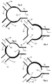
- Fig. 2 the angles are by means of a sectional view represented by the center plane of the connection cross-sections. All angles are directly related with the cross-sectional functions. In addition to the relatively simple form of a hole for the openings you can also choose other, non-circular cross-sections become. That way you can get another one Degree of freedom in determining the actuating behavior to reach.
- connection piece 13, 15 and 17 radially from the valve housing 3 from.
- the valve housing could also have a cone shape instead of a cylindrical shape, then the rotary valve 3 in its shape also adapt accordingly to the cone shape would.
- Short circuit e.g. for the cylinder head be.
- heating circuit and / or the short-circuit circuit line 14 another or two other sub-circuits can be provided. That's the way it is e.g. possible a partial circuit for additional heating and / or a further partial circuit for one Provide exhaust gas heat exchanger device.
- the rotary valve 3 can each circuit switch separately. You can also choose between each two circuits set any mixing levels become.
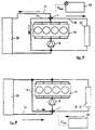
- FIG. 7 The position of the control device 1 shown in FIGS. 1 to 6 with an axial inlet from the pump 8 and the three radial outlet openings 10, 11 and 12 in the cooling and heating circuit of an internal combustion engine 19 is shown in FIG. 7.
- the flange 7 is connected to the pressure side of the pump 8.
- the arrows next to the short-circuit circuit line 14, next to the cooler line 16, which leads back to a cooler 20 and from there back to the pump 8, and next to the heating circuit line 18, in which a heat exchanger 21 is arranged, from which a return line to the pump 8 takes place, show the respective flow direction of the cooling medium.
- the control device 5 for the rotary valve 3 is actuated via U electronic control unit 22, which is not shown in detail.
- this or the rotary valve 3 according to his Position of the individual partial volume flows.
- the arrows next to it the short circuit circuit line 14, the radiator line 16 and the heating line 18 in turn show the Flow direction of the cooling medium, in this If the openings in the valve housing do not have any outlet openings, but inlet openings 10, 11 and 12 represent.
- the sanitary opening 9 thus serves for the supply line of the cooling medium to the suction side of the feed pump 8.
- the mode of operation of the control device corresponds also in this position of the control device 1 the mode of operation according to the position according to FIG. 7.
Landscapes
- Engineering & Computer Science (AREA)
- General Engineering & Computer Science (AREA)
- Mechanical Engineering (AREA)
- Chemical & Material Sciences (AREA)
- Combustion & Propulsion (AREA)
- Multiple-Way Valves (AREA)
- Taps Or Cocks (AREA)
Abstract
Description
Die Erfindung betrifft eine Steuervorrichtung für den Kühl- und Heizungskreislauf einer Brennkraftmaschine.The invention relates to a control device for the Cooling and heating circuit of an internal combustion engine.
Zur Steuerung des Kühl- und Heizungskreislaufes einer Brennkraftmaschine sind aus der Praxis Thermostate bekannt, die temperaturabhängig in der Aufwärmphase der Brennkraftmaschine einen Kurzschlußkreislauf schalten. Ebenso sind Taktventile bekannt, die im Heizungskreislauf die Kühlmittelströme schalten. Schieber- und Drehventile mit Schrittmotorenantrieb sind zur Steuerung des Kühl- und Heizungskreislaufes ebenfalls aus der Praxis bekannt.To control the cooling and heating circuit one In practice, internal combustion engines are thermostats known, the temperature-dependent in the warm-up phase the internal combustion engine a short circuit switch. Clock valves are also known, which are in the heating circuit switch the coolant flows. Spool and rotary valves with stepper motor drive are to control the cooling and heating circuit as well known from practice.
Aus der DE 43 24 749 A1 ist ein Regelventil für den Kühlkreislauf bekannt, mit einem radialen Zulauf und drei radialen Abgängen, wobei die Verteilung des Kühlmittels durch einen Drehschieber erfolgt. DE 43 24 749 A1 describes a control valve for the Known cooling circuit, with a radial inlet and three radial outlets, the distribution of the coolant done by a rotary valve.
Nachteilig bei diesem Regelventil ist jedoch, daß man stets resultierende Kräfte auf den Drehschieber hat, die zu Verklemmungen führen können und/oder entsprechend starke Antriebsmotoren zu dessen Verstellung erforderlich machen. Darüber hinaus sind die Verstell- bzw. Mischstellungen beschränkt.A disadvantage of this control valve, however, is that always has resulting forces on the rotary valve, which can lead to deadlocks and / or accordingly strong drive motors for its adjustment make necessary. In addition, the adjustment or Mixed positions limited.
Aus der DE 41 25 366 C1 ist ein 3/2-Wegeventil für Flüssigkeitskreisläufe in Fahrzeugen bekannt, mit einem axialen Zulauf und zwei radialen Abführungen. Auch bei diesem Ventil sind die Einstellmöglichkeiten beschränkt, so daß zur Steuerung bzw. Regelung eines Kühl- und Heizungskreislaufes noch weitere Einrichtungen erforderlich sind.From DE 41 25 366 C1 is a 3/2-way valve for Liquid circuits in vehicles known with a axial inlet and two radial outlets. Also the setting options for this valve are limited, so that for the control or regulation of a Cooling and heating circuit still other facilities required are.
Der vorliegenden Erfindung liegt die Aufgabe zugrunde, eine Steuervorrichtung zu schaffen, in der mehrere Funktionen von Stell- und Schaltelementen derart integriert sind, daB im Bedarfsfalle weitere Regelglieder in einem Kühl- und Heizungskreislauf eines Kraftfahrzeuges entfallen können.The present invention is based on the object to create a control device in which several Functions of control and switching elements integrated in this way are that additional control elements are required in a cooling and heating circuit of a motor vehicle can be omitted.
Erfindungsgemäß wird diese Aufgabe durch die in Anspruch 1 genannten Merkmale gelöst.According to the invention, this object is achieved by the 1 mentioned features solved.
Mit der erfindungsgemäßen Steuervorrichtung kann mit einem einzigen Gerät der gesamte Kreislauf zur Kühlung und zur Heizung für nahezu alle in der Praxis vorkommenden Fälle geregelt werden. Es sind sowohl einzelne Öffnungen ansteuerbar als auch Mischbetriebe möglich, so daß auf weitere Steuer- und Regelglieder im Kühl- und Heizungskreislauf verzichtet werden kann.With the control device according to the invention can with the entire cooling circuit in a single device and for heating for almost everyone in practice Cases are regulated. They are both individual Controllable openings as well as mixed operations possible so that on further control and regulating elements in the cooling and Heating circuit can be dispensed with.
Ein weiterer Vorteil der erfindungsgemäßen Lösung liegt darin, daß aufgrund der axialen Zuführung oder Abführung und den Zulauf- oder Auslauföffnungen am Umfang des Ventilgehäuses keine resultierenden Kräfte auf den Drehschieber wirken, womit man mit geringen Stell- und Haltekräften für den Drehschieber auskommt.Another advantage of the solution according to the invention is that due to the axial feed or Discharge and the inlet or outlet openings on Circumference of the valve housing no resulting forces act on the rotary valve, with which you can with low Actuating and holding forces for the rotary valve is sufficient.
Durch die erfindungsgemäße Anordnung sind neben den Einzelströmungen alle in der Praxis auftretenden Mischstufen realisierbar. Darüber hinaus treten bei der erfindungsgemäßen Stellvorrichtung nur geringe Druckverluste auf, bei gleichzeitig hohen Stellgeschwindigkeiten.Due to the arrangement according to the invention are in addition to Single flows all occurring in practice Mixing levels possible. Beyond join the actuating device according to the invention only slight Pressure losses on, at high speeds.
Legt man die Zulauf- oder Auslauföffnungen in eine gleiche Radialebene, so wird zusätzlich noch eine sehr kompakte Bauweise erreicht.Put the inlet or outlet openings in one same radial plane, so there is also a very compact design achieved.
Die erfindungsgemäße Steuervorrichtung läßt sich in zwei Richtungen betreiben, nämlich mit einem axialen Zulauf und entsprechenden Abgängen bzw. Auslauföffnungen am Umfang, wobei die Sammelöffnung mit der Druckseite einer Förderpumpe verbunden ist oder auch umgekehrt, wobei die Sammelöffnung mit der Saugseite einer Förderpumpe verbunden ist und über die Umfangswand des Drehschiebers entsprechend die Zuläufe vom Kühler und von weiteren Teilkreisläufen erfolgen.The control device according to the invention can be in operate in two directions, namely with one axial Inlet and corresponding outlets or outlet openings on the circumference, the collecting opening with the pressure side is connected to a feed pump or vice versa, the collecting opening with the suction side of a Feed pump is connected and over the peripheral wall of the Rotary valve according to the inlets from the cooler and of further sub-cycles.
In den Unteransprüchen und in dem nachfolgend anhand der Zeichnung prinzipmäßig beschriebenen Ausführungsbeispiel sind vorteilhafte Weiterbildungen und Ausgestaltungen der Erfindung aufgezeigt. In the dependent claims and in the following based on the drawing described in principle embodiment are advantageous developments and refinements shown the invention.
Es zeigt:
- Fig. 1
- eine perspektivische Darstellung der erfindungsgemäßen Steuervorrichtung;
- Fig. 2
- einen schematischen Querschnitt durch die erfindungsgemäße Steuervorrichtung;
- Fig. 3-6
- verschiedene Steuerstellungen der Steuervorrichtung;
- Fig. 7
- die Anordnung der erfindungsgemäßen Steuervorrichtung in einem Kühl- und Heizungskreislauf; und
- Fig. 8
- eine zweite Anordnungsmöglichkeit der erfindungsgemäßen Steuervorrichtung in dem Kühl- und Heizungskreislauf.
- Fig. 1
- a perspective view of the control device according to the invention;
- Fig. 2
- a schematic cross section through the control device according to the invention;
- Fig. 3-6
- different control positions of the control device;
- Fig. 7
- the arrangement of the control device according to the invention in a cooling and heating circuit; and
- Fig. 8
- a second possibility of arranging the control device according to the invention in the cooling and heating circuit.
Gemäß Fig. 1 weist die Steuervorrichtung 1 ein zylinderförmiges
Ventilgehäuse 2 auf, in welchem ein hülsenförmiger
Drehschieber 3 gelagert ist. Der Drehschieber
3 ist mit einer axialen Sammelöffnung 4 auf
einer Stirnseite versehen, während er auf der anderen
Seite geschlossen und mit einer Antriebseinrichtung 5
zu dessen Verschwenkung um seine Längsachse versehen
ist. Das Ventilgehäuse 2 ist auf der von der Antriebseinrichtung
5 abgewandten Seite mit einem Deckel
6 mit einem zentralen Flansch 7 versehen, über den
eine Verbindung mit einer in den Fig. 7 und 8 dargestellten
Pumpe 8 zu der Sammelöffnung 4 erfolgt.1, the
Der Drehschieber 3 ist in seiner Umfangswand mit einer
Steueröffnung 9 versehen. Je nach Strömungsrichtung
wird Kühlmedium von der Sammelöffnung 4 aus über die
Steueröffnung 9 in Zulauf- oder Auslauföffnungen in
dem Ventilgehäuse 2 verteilt oder von den Zulauf- oder
Auslauföffnungen zu der Sammelöffnung 4 geführt. Bei
dem in der Fig. 1 dargestellten Ausführungsbeispiel
erfolgt der Zulauf des Kühlmediums axial über die Sammelöffnung
4 und wird von dort aus durch die Steueröffnung
9 über eine Auslauföffnung 10, 11 oder 12 weitergeleitet.
Die Auslauföffnung 10 ist mit einem Anschlußstutzen
13 versehen, über den eine Verbindung zu
einer Kurzschlußkreislaufleitung 14 erfolgt. Die Auslauföffnung
12 ist über einen Anschlußstutzen 15 mit
einer Kühlleitung 16 verbunden, während die Auslauföffnung
11 über einen Anschlußstutzen 17 mit einer
Heizungsleitung 18 verbunden ist.The
Wie aus der Fig. 2 und den verschiedenen Betriebsstellungen
in den Fig. 3 bis 6 deutlicher ersichtlich ist,
besitzt die Sammelöffnung 9 in der Umfangswand des
Drehschiebers 4 eine derartige Öffnungsweite, daß sowohl
Einzelströmungen von der Sammelöffnung 4 aus zu
einer der Auslauföffnungen 10, 11 oder 12 als auch
überlappende Verbindungen für Mischbetriebe möglich
sind.As from Fig. 2 and the
Gemäß Fig. 2 müssen hierzu folgende Bedingungen erfüllt
sein:
Dabei bedeuten:
- γ
- Öffnungswinkel des Drehschiebers
- δ
- Winkel zwischen den Stutzen
- ϕ
- Winkelöffnung der Anschlußstutzen
- β
- freigeschalteter Öffnungswinkel des entsprechenden Stutzens
- γ
- Opening angle of the rotary valve
- δ
- Angle between the nozzles
- ϕ
- Angular opening of the connecting piece
- β
- unlocked opening angle of the corresponding nozzle
In Fig. 2 sind die Winkel mittels Schnittdarstellung durch die Mittenebene der Anschlußquerschnitte dargestellt. Alle Winkel stehen in einem unmittelbaren Zusammenhang mit den Querschnittsfunktionen. Neben der relativ einfachen Form einer Bohrung für die Öffnungen können auch andere, nicht kreisrunde Querschnitte gewählt werden. Auf diese Weise kann man einen weiteren Freiheitsgrad bei der Festlegung des Stellverhaltens erreichen.In Fig. 2 the angles are by means of a sectional view represented by the center plane of the connection cross-sections. All angles are directly related with the cross-sectional functions. In addition to the relatively simple form of a hole for the openings you can also choose other, non-circular cross-sections become. That way you can get another one Degree of freedom in determining the actuating behavior to reach.
Bei dem dargestellten Ausführungsbeispiel gehen die
Anschlußstutzen 13, 15 und 17 radial von dem Ventilgehäuse
3 ab. Um eine strömungsgünstigere Form zu erreichen,
ist es auch möglich die Anschlußstutzen halbaxial
bzw. gegen die Radiale geneigt an das Ventilgehäuse
2 anzusetzen. Ebenso könnte das Ventilgehäuse
selbst statt einer Zylinderform eine Kegelform aufweisen,
wobei dann der Drehschieber 3 in seiner Form
ebenfalls entsprechend an die Kegelform anzupassen
wäre.In the illustrated embodiment, the
In den Fig. 3 bis 6 sind verschiedene Steuerstellungen
der Steuervorrichtung 1 dargestellt. So zeigt Fig. 3
die Stellung im Normalbetrieb ![]()
![]()
Die Fig. 6 zeigt einen dritten Mischbetrieb in der
Phase
Entsprechend dem in der Fig. 3 dargestellten Betrieb sind auch im Bedarfsfalle noch andere einzelne Verbindungen von der Steueröffnung 9 zu einer einzelnen Auslauföffnung möglich.Corresponding to the operation shown in FIG. 3 are other individual connections if necessary from the control opening 9 to a single outlet opening possible.
Anstelle des Heizungskreislaufes kann auch ein zweiter Kurzschlußkreis, z.B. für den Zylinderkopf, vorgesehen sein.Instead of the heating circuit, a second one can also be used Short circuit, e.g. for the cylinder head be.
Ebenso kann anstelle des Heizungskreislaufes und/oder
der Kurzschlußkreislaufleitung 14 ein anderer oder
zwei andere Teilkreisläufe vorgesehen sein. So ist es
z.B. möglich, einen Teilkreislauf für eine Zusatzheizung
und/oder einen weiteren Teilkreislauf für eine
Abgaswärmetauschereinrichtung vorzusehen.Likewise, instead of the heating circuit and / or
the short-
Wie ersichtlich, kann der Drehschieber 3 jeden Kreislauf
separat schalten. Zusätzlich können zwischen jeweils
zwei Kreislaufen jegliche Mischstufen eingestellt
werden.As can be seen, the
An der Steuervorrichtung 1 liegen keine resultierenden
Strömungskräfte vor, die ein Moment um die Drehachse
des Drehschiebers 3 erzeugen würden. Dies bedeutet
Veränderungen der Drehschieberstellung infolge einer
Durchströmung sind nicht möglich, weshalb die Antriebsleistung
für die Antriebseinrichtung 5 entsprechend
gering gehalten werden kann. Durch die geringen
Stellkräfte ist im Normalfall auch keine besondere
Lagerung des Drehschiebers 3 erforderlich. Da in jeder
Winkelstellung Querschnitte in radialer Richtung freigeschaltet
sind, treten außerdem auch nur sehr geringe
Druckabfälle über der Steuervorrichtung auf, womit
besondere Abdichtungen der einzelnen Zu- und Abläufe
entfallen können.There are no resulting ones on the
Bei dem dargestellten Ausführungsbeispiel liegen alle
Auslauföffnungen 10, 11 und 12 in der gleichen Radialebene,
womit eine sehr kurze Baulänge erreicht wird.In the illustrated embodiment, all are
Die Lage der in den Fig. 1 bis 6 dargestellten Steuervorrichtung
1 mit einem axialen Zulauf von der Pumpe 8
und den drei radialen Auslauföffnungen 10, 11 und 12
in dem Kühl- und Heizungskreislauf einer Brennkraftmaschine
19 ist in der Fig. 7 dargestellt. In diesem
Falle ist der Flansch 7 mit der Druckseite der Pumpe 8
verbunden. Die Pfeile neben der Kurzschlußkreislaufleitung
14, neben der Kühlerleitung 16, die zu einem
Kühler 20 und von da aus wieder Zur Pumpe 8 zurückführt,
und neben der Heizungskreislaufleitung 18, in
der ein Wärmetauscher 21 angeordnet ist, von welchem
eine Rückleitung zur Pumpe 8 erfolgt, zeigen die jeweilige
Strömungsrichtung des Kühlmediums. Über eine
nicht näher dargestellte Steuerungselektronik 22 erfolgt
mit USoll eine Ansteuerung der Antriebseinrichtung
5 für den Drehschieber 3.The position of the
Bei der in der Fig. 7 dargestellten Lage der Steuervorrichtung
verteilt der Drehschieber 3 entsprechend
seiner Stellung die einzelnen Teilvolumenströme. In the position of the control device shown in FIG. 7
distributes the
Gemäß Lage der Steuervorrichtung nach der Fig. 8 vereint
diese bzw. der Drehschieber 3 entsprechend seiner
Stellung die einzelnen Teilvolumenströme. Wie ersichtlich,
ist dabei der Flansch 7 saugseitig bzw. eingangsseitig
mit der Pumpe 8 verbunden. Die Pfeile neben
der Kurzschlußkreislaufleitung 14, der Kühlerleitung
16 und der Heizungsleitung 18 zeigen wiederum die
Strömungsrichtung des Kühlmediums an, wobei in diesem
Falle die Öffnungen in dem Ventilgehäuse keine Auslauföffnungen,
sondern Zulauföffnungen 10, 11 und 12
darstellen. Die Sanmelöffnung 9 dient damit zur Zuleitung
des Kühlmediums zur Saugseite der Förderpumpe 8.
Die Wirkungsweise der Steuervorrichtung entspricht
auch bei dieser Lage der Steuervorrichtung 1 der Wirkungsweise
gemäß Lage nach der Fig. 7.Combined according to the position of the control device according to FIG. 8
this or the
Claims (7)
dadurch gekennzeichnet, daß
die weiteren Teilkreisläufe für eine Kurzschlußkreislaufleitung (14) des Kühlwassers und für eine zu dem Wärmetauscher (21) des Heizungskreislaufes führende Heizungsleitung (18) vorgesehen sind.Control device according to claim 1,
characterized in that
the further sub-circuits are provided for a short-circuit circuit line (14) of the cooling water and for a heating line (18) leading to the heat exchanger (21) of the heating circuit.
dadurch gekennzeichnet, daß
eine oder beide weiteren Teilkreisläufe für eine Zusatzheizung und/oder eine Abgaswärmetauschereinrichtung vorgesehen sind.Control device according to claim 1,
characterized in that
one or both further sub-circuits are provided for additional heating and / or an exhaust gas heat exchanger device.
dadurch gekennzeichnet, daß
die Zulauf- oder Auslauföffnungen (10,11,12) in einer gleichen Radialebene liegen.Control device according to one of claims 1 to 3,
characterized in that
the inlet or outlet openings (10, 11, 12) lie in the same radial plane.
dadurch gekennzeichnet, daß
die Winkelabstände zwischen den Zulauf- oder Auslauföffnungen (10,11,12) gleichmäßig über den Umfang des Ventilgehäuses (2) verteilt sind.Control device according to claim 4,
characterized in that
the angular distances between the inlet or outlet openings (10, 11, 12) are evenly distributed over the circumference of the valve housing (2).
dadurch gekennzeichnet, daß
von den Zulauf- oder Auslauföffnungen (10,11,12) Anschlußstutzen (13,15,17) halbaxial abzweigen. Control device according to one of claims 1 to 5,
characterized in that
From the inlet or outlet openings (10, 11, 12) branch connection (13, 15, 17) semi-axially.
dadurch gekennzeichnet, daß
der Drehschieber (3) auf der von der axialen Sammelöffnung (4) abgewandten Seite mit einer Antriebseinrichtung (5) in Verbindung steht.Control device according to one of claims 1 to 6,
characterized in that
the rotary slide valve (3) is connected to a drive device (5) on the side facing away from the axial collecting opening (4).
Applications Claiming Priority (2)
| Application Number | Priority Date | Filing Date | Title |
|---|---|---|---|
| DE19809124 | 1998-03-04 | ||
| DE19809124A DE19809124A1 (en) | 1998-03-04 | 1998-03-04 | Control device for the cooling and heating circuit of an internal combustion engine |
Publications (3)
| Publication Number | Publication Date |
|---|---|
| EP0940566A2 true EP0940566A2 (en) | 1999-09-08 |
| EP0940566A3 EP0940566A3 (en) | 2000-03-01 |
| EP0940566B1 EP0940566B1 (en) | 2004-03-31 |
Family
ID=7859613
Family Applications (1)
| Application Number | Title | Priority Date | Filing Date |
|---|---|---|---|
| EP99102206A Expired - Lifetime EP0940566B1 (en) | 1998-03-04 | 1999-02-04 | Control device for the cooling - and heating circuit of an internal combustion engine |
Country Status (4)
| Country | Link |
|---|---|
| US (1) | US6164248A (en) |
| EP (1) | EP0940566B1 (en) |
| JP (1) | JP2000034922A (en) |
| DE (2) | DE19809124A1 (en) |
Cited By (5)
| Publication number | Priority date | Publication date | Assignee | Title |
|---|---|---|---|---|
| EP2021666A2 (en) * | 2006-05-15 | 2009-02-11 | Thomas J. Hollis | Digital rotary control valve |
| CN103075239A (en) * | 2011-10-26 | 2013-05-01 | 曼卡车和巴士股份公司 | Coolant circuit for a liquid-cooled internal combustion engine |
| FR3002281A1 (en) * | 2013-02-19 | 2014-08-22 | Peugeot Citroen Automobiles Sa | Cooling circuit for thermal engine of car, has thermostatic valve located in inlet manifold upstream of feed pump, where valve blocks flow of coolant in inlet manifold as long as coolant temperature is below threshold temperature |
| WO2015110343A1 (en) * | 2014-01-23 | 2015-07-30 | Bayerische Motoren Werke Aktiengesellschaft | Heat management system for an internal combustion engine |
| EP2955459A1 (en) * | 2014-06-12 | 2015-12-16 | Bosch Termotecnologia S.A. | Feed-in device, multiway valve, system and method for operating such a system |
Families Citing this family (58)
| Publication number | Priority date | Publication date | Assignee | Title |
|---|---|---|---|---|
| DE19932313A1 (en) | 1999-07-10 | 2001-01-18 | Daimler Chrysler Ag | Controller for internal combustion engine cooling, heating circuit has rotary disc on valve housing, drive unit, cooling line openings in housing for delivery to supply pump and sub-circuits |
| DE19957145C2 (en) * | 1999-11-27 | 2002-10-31 | Daimler Chrysler Ag | Device for circulating coolant and controlling coolant flows in a cooling system |
| DE10014555C2 (en) * | 2000-03-23 | 2003-06-18 | Daimler Chrysler Ag | Control device for the cooling circuit of an internal combustion engine |
| DE10064671A1 (en) * | 2000-12-21 | 2002-06-27 | Behr Gmbh & Co | Valve for vehicle heating system has sliding element range greater than adjustment range required to regulate one inlet or outlet opening; other openings can be regulated outside this range |
| DE10101412B4 (en) * | 2001-01-13 | 2014-05-28 | Pierburg Gmbh | Exhaust gas recirculation device for an internal combustion engine |
| DE10101826B4 (en) | 2001-01-17 | 2006-12-21 | Daimlerchrysler Ag | Control device for the cooling circuit of an internal combustion engine |
| FR2827359B1 (en) * | 2001-07-11 | 2004-11-05 | Valeo Thermique Moteur Sa | CONTROL VALVE FOR A COOLING CIRCUIT OF A MOTOR VEHICLE HEAT ENGINE |
| US6681805B2 (en) * | 2001-11-28 | 2004-01-27 | Ranco Incorporated Of Delaware | Automotive coolant control valve |
| FR2833996B1 (en) * | 2001-12-21 | 2004-03-19 | Mark Iv Systemes Moteurs Sa | PUMP / VALVE ASSEMBLY AND COOLING CIRCUIT COMPRISING SUCH AN ASSEMBLY |
| US6539899B1 (en) * | 2002-02-11 | 2003-04-01 | Visteon Global Technologies, Inc. | Rotary valve for single-point coolant diversion in engine cooling system |
| DE10206359A1 (en) * | 2002-02-14 | 2003-09-04 | Daimler Chrysler Ag | Thermostatic valve for coolant circuit in internal combustion engine has adjusting device for second shut-off element so that shut-off component can first be brought into alternate positions closing off one or two of three flow ports |
| FR2849485B1 (en) * | 2002-12-30 | 2005-09-02 | Valeo Thermique Moteur Sa | ENHANCED SEAL CONTROL VALVE FOR FLUID CIRCULATION CIRCUIT |
| FR2849673B1 (en) | 2003-01-03 | 2006-08-04 | Peugeot Citroen Automobiles Sa | BARREL ACTUATOR FOR SEPARATE COOLING ENGINE |
| US6920845B2 (en) * | 2003-08-14 | 2005-07-26 | Visteon Global Technologies, Inc. | Engine cooling disc valve |
| DE10351852A1 (en) * | 2003-11-06 | 2005-06-16 | Itw Automotive Products Gmbh & Co. Kg | Cooling system for combustion in machines, especially for automobiles |
| US6997143B2 (en) * | 2003-12-12 | 2006-02-14 | Visteon Global Technologies, Inc. | Integrated heat exchange and fluid control device |
| WO2005059349A1 (en) * | 2003-12-15 | 2005-06-30 | Inergy Automotive Systems Research (Société Anonyme) | Electronically controlled electromechanical valve |
| FR2872240B1 (en) * | 2004-06-28 | 2008-02-01 | Valeo Thermique Moteur Sas | CONTROL VALVE FOR A FLUID CIRCUIT CIRCUIT, ESPECIALLY FOR A COOLING CIRCUIT OF AN ENGINE |
| JP2008530423A (en) * | 2005-02-07 | 2008-08-07 | ボーグワーナー・インコーポレーテッド | Exhaust throttle EGR valve module for diesel engine |
| FR2893113B1 (en) * | 2005-11-04 | 2009-03-06 | Valeo Systemes Thermiques | ENHANCED SEAL CONTROL VALVE FOR FLUID CIRCULATION CIRCUIT |
| US7343882B2 (en) * | 2006-04-07 | 2008-03-18 | Emp Advanced Development, Inc. | Fluid valve |
| US7412948B2 (en) * | 2006-04-07 | 2008-08-19 | Emp Advanced Development, Llc | Fluid valve |
| US7506664B2 (en) * | 2006-04-27 | 2009-03-24 | Ranco Incorporated Of Delaware | Automotive coolant control valve |
| FR2901572A1 (en) * | 2006-05-26 | 2007-11-30 | Mark Iv Systemes Moteurs Soc P | COOLING CIRCUIT OF AN INTERNAL COMBUSTION ENGINE |
| FR2916479B1 (en) * | 2007-05-25 | 2012-12-21 | Valeo Systemes Thermiques | MODULE FOR A COOLING CIRCUIT OF A MOTOR VEHICLE ENGINE. |
| DE102008030768A1 (en) * | 2008-06-28 | 2009-12-31 | Audi Ag | Internal combustion engine, has disk valve with end area rotatably accommodated with intake mouth such that coolant opening lies in intake opening and/or end area rotatably overlaps mouth so that intake opening lies in coolant opening |
| DE102008058321A1 (en) * | 2008-11-21 | 2010-05-27 | Audi Ag | Internal combustion engine, has rotary valve supported in housing by axle, which is held in rotary valve by supporting element and held in housing by carrier element, where supporting and carrier elements are formed as radial arm structure |
| KR101080764B1 (en) | 2009-03-19 | 2011-11-07 | 현대자동차주식회사 | Thermostat Valve for Vehicle |
| DE102009020187B4 (en) | 2009-05-06 | 2012-11-08 | Audi Ag | Coolant circuit |
| DE102009032647A1 (en) * | 2009-07-08 | 2011-01-13 | Illinois Tool Works Inc., Glenview | Cooling system for an internal combustion engine |
| ES1071687Y (en) * | 2010-01-11 | 2010-06-22 | Omar Vallortigara | VALVE DEVICE FOR A FLUID CIRCULATION CIRCUIT |
| DE102010064472B3 (en) * | 2010-02-10 | 2015-05-13 | Ford Global Technologies, Llc | Method of operating a cooling system and cooling system |
| DE102010001752B4 (en) * | 2010-02-10 | 2012-06-21 | Ford Global Technologies, Llc | cooling system |
| DE102010002605B4 (en) * | 2010-03-05 | 2013-12-12 | Ford Global Technologies, Llc | Method for shortening the warm-up phase by means of heat recovery from recirculated exhaust gases |
| JP5381851B2 (en) * | 2010-03-25 | 2014-01-08 | トヨタ自動車株式会社 | Refrigerant flow control device and vehicle cooling device |
| KR101230990B1 (en) * | 2010-09-13 | 2013-02-07 | 기아자동차주식회사 | 3 way valve integrated with radiator |
| KR101283086B1 (en) * | 2011-08-16 | 2013-07-05 | 현대자동차주식회사 | Cooling water distributor |
| US9689393B2 (en) * | 2012-02-14 | 2017-06-27 | Pierburg Pump Technology Gmbh | Mechanical coolant pump |
| US9032915B2 (en) * | 2012-07-30 | 2015-05-19 | Ford Global Technologies, Llc | Independent cooling of cylinder head and block |
| US9897217B2 (en) | 2013-05-17 | 2018-02-20 | Magna Powertrain Inc. | Low-drag sealing method for thermal management valve |
| US9500299B2 (en) * | 2013-07-25 | 2016-11-22 | Schaeffler Technologies AG & Co. KG | Thermal management valve module with isolated flow chambers |
| US9523307B2 (en) * | 2014-09-22 | 2016-12-20 | Hyundai Motor Company | Engine system having coolant control valve |
| JP6319018B2 (en) * | 2014-09-25 | 2018-05-09 | マツダ株式会社 | Engine cooling system |
| DE102015201244B3 (en) * | 2015-01-26 | 2016-05-12 | Ford Global Technologies, Llc | Control means for controlling the coolant flows of a split cooling system |
| US10337389B2 (en) | 2015-01-26 | 2019-07-02 | Ford Global Technologies, Llc | Control means for controlling the coolant flows of a split cooling system |
| JP6225949B2 (en) * | 2015-06-23 | 2017-11-08 | トヨタ自動車株式会社 | Cooling device for internal combustion engine |
| DE102015009501A1 (en) | 2015-07-22 | 2017-01-26 | GM Global Technology Operations LLC (n. d. Ges. d. Staates Delaware) | Engine cooling |
| JP6330748B2 (en) * | 2015-07-29 | 2018-05-30 | トヨタ自動車株式会社 | Cooling device for internal combustion engine |
| SE1551095A1 (en) * | 2015-08-25 | 2017-02-26 | Scania Cv Ab | Thermostat device |
| SE541819C2 (en) | 2016-05-16 | 2019-12-27 | Scania Cv Ab | A multi-valve device for a cooling system |
| DE102018106208A1 (en) * | 2017-06-28 | 2019-01-03 | Yamada Manufacturing Co., Ltd. | control valve |
| JP6496364B2 (en) * | 2017-08-09 | 2019-04-03 | 株式会社Subaru | Cooling control device |
| US10865668B2 (en) * | 2017-11-03 | 2020-12-15 | Nio Usa, Inc. | Four-way hydraulic valve flow control body |
| JP2019167943A (en) * | 2018-03-26 | 2019-10-03 | 株式会社山田製作所 | Control valve |
| DE102019133340A1 (en) * | 2019-12-06 | 2021-06-10 | Jopp Holding GmbH | VALVE, MULTIPLE VALVE SYSTEM AND VEHICLE WITH VALVE |
| US11454198B2 (en) * | 2020-09-28 | 2022-09-27 | Ford Global Technologies, Llc | Method and system for distribution of exhaust gas |
| FR3135504A1 (en) * | 2022-05-10 | 2023-11-17 | Bontaz Centre R&D | DRIVE DEVICE FOR A ROTARY VALVE |
| FR3135503A1 (en) * | 2022-05-10 | 2023-11-17 | Bontaz Centre R&D | PROPORTIONAL ROTARY VALVE |
Citations (2)
| Publication number | Priority date | Publication date | Assignee | Title |
|---|---|---|---|---|
| DE4125366C1 (en) | 1991-07-31 | 1993-03-11 | Eberspaecher J | Applying 3-2 path valve in fluid circuit of motor vehicle - using valve slide to block respective flow paths in end positions |
| DE4324749A1 (en) | 1993-07-23 | 1995-01-26 | Freudenberg Carl Fa | Control valve |
Family Cites Families (10)
| Publication number | Priority date | Publication date | Assignee | Title |
|---|---|---|---|---|
| US2401646A (en) * | 1945-02-28 | 1946-06-04 | Johnson John Frank | Temperature control for cooling fluid of internal-combustion engines |
| FR1460040A (en) * | 1965-10-14 | 1966-06-17 | Chausson Usines Sa | Method for regulating the cooling circuit of a heat engine according to climatic conditions and device for its implementation |
| JPS5629224A (en) * | 1979-08-17 | 1981-03-24 | Toshiba Corp | X-ray photographing apparatus |
| JPS60237116A (en) * | 1984-05-10 | 1985-11-26 | Aisin Seiki Co Ltd | Method and device of cooling control in engine |
| JPH0633756B2 (en) * | 1984-05-25 | 1994-05-02 | マツダ株式会社 | Engine warm-up promotion device |
| JPS6316121A (en) * | 1986-07-07 | 1988-01-23 | Aisin Seiki Co Ltd | Cooling device for internal combustion engine |
| JP2767995B2 (en) * | 1989-12-28 | 1998-06-25 | 株式会社デンソー | Internal combustion engine cooling system |
| JPH0723872A (en) * | 1993-07-05 | 1995-01-27 | Toto Ltd | Appliance for housing kitchen small articles |
| DE4416039C1 (en) * | 1994-05-06 | 1995-08-31 | Freudenberg Carl Fa | Mixer control valve |
| JPH09264440A (en) * | 1996-03-28 | 1997-10-07 | Borusuku:Kk | Directional control valve |
-
1998
- 1998-03-04 DE DE19809124A patent/DE19809124A1/en not_active Withdrawn
-
1999
- 1999-02-04 EP EP99102206A patent/EP0940566B1/en not_active Expired - Lifetime
- 1999-02-04 DE DE59908986T patent/DE59908986D1/en not_active Expired - Lifetime
- 1999-03-03 JP JP11099187A patent/JP2000034922A/en active Pending
- 1999-03-04 US US09/262,722 patent/US6164248A/en not_active Expired - Fee Related
Patent Citations (2)
| Publication number | Priority date | Publication date | Assignee | Title |
|---|---|---|---|---|
| DE4125366C1 (en) | 1991-07-31 | 1993-03-11 | Eberspaecher J | Applying 3-2 path valve in fluid circuit of motor vehicle - using valve slide to block respective flow paths in end positions |
| DE4324749A1 (en) | 1993-07-23 | 1995-01-26 | Freudenberg Carl Fa | Control valve |
Cited By (10)
| Publication number | Priority date | Publication date | Assignee | Title |
|---|---|---|---|---|
| EP2021666A2 (en) * | 2006-05-15 | 2009-02-11 | Thomas J. Hollis | Digital rotary control valve |
| EP2021666A4 (en) * | 2006-05-15 | 2013-03-20 | Thomas J Hollis | Digital rotary control valve |
| CN103075239A (en) * | 2011-10-26 | 2013-05-01 | 曼卡车和巴士股份公司 | Coolant circuit for a liquid-cooled internal combustion engine |
| CN103075239B (en) * | 2011-10-26 | 2017-07-11 | 曼卡车和巴士股份公司 | For the cooling circuit of the internal combustion engine of liquid cooling |
| FR3002281A1 (en) * | 2013-02-19 | 2014-08-22 | Peugeot Citroen Automobiles Sa | Cooling circuit for thermal engine of car, has thermostatic valve located in inlet manifold upstream of feed pump, where valve blocks flow of coolant in inlet manifold as long as coolant temperature is below threshold temperature |
| WO2015110343A1 (en) * | 2014-01-23 | 2015-07-30 | Bayerische Motoren Werke Aktiengesellschaft | Heat management system for an internal combustion engine |
| CN105745411A (en) * | 2014-01-23 | 2016-07-06 | 宝马股份公司 | Heat management system for an internal combustion engine |
| US10023025B2 (en) | 2014-01-23 | 2018-07-17 | Bayerische Motoren Werke Aktiengesellschaft | Heat management system for an internal combustion engine |
| CN105745411B (en) * | 2014-01-23 | 2018-10-12 | 宝马股份公司 | Heat management system for internal combustion engine |
| EP2955459A1 (en) * | 2014-06-12 | 2015-12-16 | Bosch Termotecnologia S.A. | Feed-in device, multiway valve, system and method for operating such a system |
Also Published As
| Publication number | Publication date |
|---|---|
| JP2000034922A (en) | 2000-02-02 |
| EP0940566B1 (en) | 2004-03-31 |
| DE19809124A1 (en) | 1999-09-16 |
| DE59908986D1 (en) | 2004-05-06 |
| US6164248A (en) | 2000-12-26 |
| EP0940566A3 (en) | 2000-03-01 |
Similar Documents
| Publication | Publication Date | Title |
|---|---|---|
| EP0940566A2 (en) | Control device for the cooling - and heating circuit of an internal combustion engine | |
| DE19809123B4 (en) | Water pump for the cooling circuit of an internal combustion engine | |
| DE102006050826B4 (en) | Rotary valve with several cross section adjustment members | |
| DE19849492B4 (en) | Control device for a cooling circuit of an internal combustion engine | |
| DE19932313A1 (en) | Controller for internal combustion engine cooling, heating circuit has rotary disc on valve housing, drive unit, cooling line openings in housing for delivery to supply pump and sub-circuits | |
| DE69919583T2 (en) | DEVICE FOR A COMBUSTION ENGINE WITH CHARGING | |
| EP1030050A1 (en) | Exhaust gas recirculation system | |
| DE102014108805A1 (en) | Internal combustion engine with multiple flow path control valve | |
| DE10154595A1 (en) | Cooling device for a vehicle with an electric motor fed by a fuel cell | |
| WO2007003303A1 (en) | Internal combustion engine with cooling system and exhaust gas recirculation system | |
| DE102008031684B4 (en) | cooling device | |
| EP2376861A2 (en) | Heat transfer unit | |
| EP0054792A2 (en) | Cooling device for cooling a combustion engine and the charge | |
| DE102019107190A1 (en) | Valve and heating system with such a valve | |
| DE102013209582A1 (en) | Rotary slide ball for a thermal management module | |
| DE19741861B4 (en) | Device for controlling the cooling water circuit for an internal combustion engine | |
| DE10127219A1 (en) | Cooling system for internal combustion engine has coolant outlet of one row of cylinders connected to radiator inlet, that of another connected to thermostatic valve short circuit inlet | |
| DE10351845A1 (en) | Exhaust gas heat exchanger for motor vehicle internal combustion engine has low and high temperature branches with individual heat exchangers | |
| EP2626526B1 (en) | Valve device | |
| EP1727976B1 (en) | Internal combustion engine having a humidifying device and a heat exchanger | |
| DE19957145C2 (en) | Device for circulating coolant and controlling coolant flows in a cooling system | |
| EP1213547A2 (en) | Independent engine heater of a motor car | |
| EP1008471B1 (en) | Coolant and heating circulation and heat exchanger for vehicles with additional coolant heater | |
| DE102008013675B4 (en) | Internal design of the housing of a coolant pump with multiple outlet channels | |
| WO2001083959A1 (en) | Cooling circuit for a multi-cylinder internal combustion engine |
Legal Events
| Date | Code | Title | Description |
|---|---|---|---|
| PUAI | Public reference made under article 153(3) epc to a published international application that has entered the european phase |
Free format text: ORIGINAL CODE: 0009012 |
|
| AK | Designated contracting states |
Kind code of ref document: A2 Designated state(s): DE FR GB IT SE |
|
| AX | Request for extension of the european patent |
Free format text: AL;LT;LV;MK;RO;SI |
|
| PUAL | Search report despatched |
Free format text: ORIGINAL CODE: 0009013 |
|
| AK | Designated contracting states |
Kind code of ref document: A3 Designated state(s): AT BE CH CY DE DK ES FI FR GB GR IE IT LI LU MC NL PT SE |
|
| AX | Request for extension of the european patent |
Free format text: AL;LT;LV;MK;RO;SI |
|
| 17P | Request for examination filed |
Effective date: 20000129 |
|
| AKX | Designation fees paid |
Free format text: DE FR GB IT SE |
|
| GRAP | Despatch of communication of intention to grant a patent |
Free format text: ORIGINAL CODE: EPIDOSNIGR1 |
|
| GRAS | Grant fee paid |
Free format text: ORIGINAL CODE: EPIDOSNIGR3 |
|
| GRAA | (expected) grant |
Free format text: ORIGINAL CODE: 0009210 |
|
| PUAC | Information related to the publication of a b1 document modified or deleted |
Free format text: ORIGINAL CODE: 0009299EPPU |
|
| STAA | Information on the status of an ep patent application or granted ep patent |
Free format text: STATUS: THE APPLICATION HAS BEEN WITHDRAWN |
|
| AK | Designated contracting states |
Kind code of ref document: B1 Designated state(s): DE FR GB IT SE |
|
| REG | Reference to a national code |
Ref country code: GB Ref legal event code: FG4D Free format text: NOT ENGLISH |
|
| DB1 | B1 document deleted | ||
| 18W | Application withdrawn |
Effective date: 20040212 |
|
| REF | Corresponds to: |
Ref document number: 59908986 Country of ref document: DE Date of ref document: 20040506 Kind code of ref document: P |
|
| REG | Reference to a national code |
Ref country code: GB Ref legal event code: FG4C Free format text: THE PATENT WAS ACTUALLY WITHDRAWN AT THE EPO ON 20040212 |
|
| EN | Fr: translation not filed |